EP1136598A1 - Faserverarbeitungsmaschine - Google Patents
Faserverarbeitungsmaschine Download PDFInfo
- Publication number
- EP1136598A1 EP1136598A1 EP01810226A EP01810226A EP1136598A1 EP 1136598 A1 EP1136598 A1 EP 1136598A1 EP 01810226 A EP01810226 A EP 01810226A EP 01810226 A EP01810226 A EP 01810226A EP 1136598 A1 EP1136598 A1 EP 1136598A1
- Authority
- EP
- European Patent Office
- Prior art keywords
- cloth
- return means
- roller
- return
- speed
- Prior art date
- Legal status (The legal status is an assumption and is not a legal conclusion. Google has not performed a legal analysis and makes no representation as to the accuracy of the status listed.)
- Withdrawn
Links
Images




Classifications
-
- D—TEXTILES; PAPER
- D01—NATURAL OR MAN-MADE THREADS OR FIBRES; SPINNING
- D01G—PRELIMINARY TREATMENT OF FIBRES, e.g. FOR SPINNING
- D01G7/00—Breaking or opening fibre bales
- D01G7/06—Details of apparatus or machines
- D01G7/08—Arrangements for feeding bales to comminuting elements
-
- D—TEXTILES; PAPER
- D01—NATURAL OR MAN-MADE THREADS OR FIBRES; SPINNING
- D01G—PRELIMINARY TREATMENT OF FIBRES, e.g. FOR SPINNING
- D01G13/00—Mixing, e.g. blending, fibres; Mixing non-fibrous materials with fibres
Definitions
- the present invention relates to a fiber processing machine, in particular a Spinning preparation device, with a riser and a movable Return means, for example a rotatable stripping roller, according to the preamble of claim 1.
- Spinning preparation facilities are mainly used in blowroom lines for the preparation of cotton in order to prepare it for spinning.
- Blowroom lines consist essentially of a bale opener, which is the raw cotton delivered opens, which is then transported in the form of flakes. In doing so coarse contaminations of the cotton are also eliminated.
- Flakes of fiber then in a mixer, for example, over different shafts ensures thorough mixing of the fiber flakes.
- the fibers then become the mixer removed from the mixer by means of a rising cloth and transported further. Such a cloth usually conveys the fiber material diagonally upwards from one Filling box.
- the object of the present invention is to improve the effect of such arrangements.
- both the conveying performance of the described fiber removal devices be increased, as well as the fiber material mixing in Memory and the resolution of the fiber lump can be improved.
- This task is accomplished by a fiber processing machine or processing method solved that a flexible retractor a movable return that is assigned to the cloth in a specified area (work area) works together, the directions of movement of the cloth and of the return means are the same (in synchronism).
- a flexible retractor a movable return that is assigned to the cloth in a specified area (work area) works together, the directions of movement of the cloth and of the return means are the same (in synchronism).
- Another important feature of the invention The device or method is the use of a baffle above the return medium. The baffle faces the return medium surface at a suitable distance from each other. With this arrangement, excess becomes Fiber material over the return means, between return means and baffle, conveyed back to memory.
- the fiber processing machine can in particular be a mixer, in particular a Be a shaft mixer.
- the shaft mixer ensures thorough mixing of the Fibers achieved while using a simple removal of the blended fibers of the rising slat is achieved.
- a pneumatic fiber fiber can be connected to the or flake transport means are provided. There is a pipeline for this proven with an air flow, as this makes the fiber flakes simple and safe can be transported further.
- the pneumatic The transport device is then connected to the separation device intended. It is also known between the slat and the transport device to provide a cleaning point - see e.g. EP-A-810 309 (machine 90).
- the spinning preparation device of Fig. 1 shows a complete blowroom line.
- This consists of a bale opener 1, which is rough cleaned 2 (e.g. according to EP-B-381 860) is subordinate. Both are via a pneumatic pipe 11 which the Fiber flakes are transported in an air stream from bale opener 1 to rough cleaning 2, connected.
- the fiber flakes are also via a pneumatic pipeline 11 after the rough cleaning 2 conveyed into a mixer 3, where the fibers before further processing be mixed.
- the fiber flakes are in the pneumatic pipes promoted like a cloud. They are in sometimes thick balls or lumps of fibers are mixed and are mixed with various foreign substances before they are cleaned.
- mixers are available for mixing the fibers to disposal.
- it is a shaft mixer 3, cf. 2, in which fibers are first deposited in shafts of different lengths, to be removed from it again, whereby mixing takes place.
- the transport air must be separated when the flakes are deposited in the shafts become.
- the fibers are removed via a riser cloth 10 which runs along the Shafts or the fibers contained therein sweeps along.
- FIG. 2 passes the riser cloth 10 the fibers to a separator 4.
- This provides the working principle of the invention according to EP-A-874070, this principle for the now the present invention is meaningless.
- An alternative is described below in Described in connection with Figures 5 and 6.
- the separator 4 the good fibers are separated from foreign fibers.
- the separating device 4 will also be described below.
- the fibers After leaving the intensive cleaning 5a, the fibers arrive to a card feeder 60, which supplies several cards 7 with fibers or fiber flakes (e.g. according to EP-B-303 023).
- Fig. 1 shows the essential blowroom machines one Cleaning line, in some cases one or the other machine, for example intensive cleaning, may not be necessary or individual machines described can occur multiple times.
- Such a fiber processing machine corresponds, for example, to the fine cleaner B60 from the applicant.
- FIG. 2 shows the shaft mixer 3 of Fig. 1 in section.
- the shaft mixer 3 is in different shafts 29 divided, open at the top and to the pneumatic Pipeline 11 are connected.
- the incoming Fiber flakes evenly distributed over the various shafts 29.
- Distributors first extend the shafts in the vertical direction before they become one Make a 90 ° bend so that the shafts and their flake fillings are now aligned extend in the horizontal direction. Your horizontal extension ends in front of you Riser 10, which on all shafts, obliquely (essentially in the vertical direction) Swipe past from below and remove the fibers.
- the fibers are transported essentially vertically and from Rising slat 10, which works with a stripping roller 17, to the separation device passed on. After passing the separation device 4 the fibers are taken over by the transport device 6 and, for example, on hand over the fine cleaner 5 (see FIG. 1) or to any other blowroom machine.
- the device 4 is designed in such a way that that which is taken over from the riser cloth 10
- the nonwoven fabric is in a vertical position both in front of the sensors 41 and in front of the blow-out nozzles 44 Moving direction.
- the nonwoven fabric is fed through the transport roller 210 Redirection by approx. 90 °.
- the separating device 4 also contains a computer 43, which is connected to the optical sensors 41 via a data line 42. As well it is connected to the blow-out nozzles 44 for control purposes.
- the sensors 41 are on the side of the nonwoven fabric 22 facing away from the mixer 3 in a horizontal Row arranged. Foreign fibers detected by the sensors are replaced by the Controlled actuation of the blow-out nozzles 44 removed from the flake stream.
- FIG. 3 shows a riser cloth 10 known from the general prior art, as in the device of FIG. 2 for removing the fibers from the shaft mixer Is used.
- the riser slat 10 is designed in the form of a needle slat, that in a known manner in spinning preparation machines as a conveyor and Opening organ is used. It essentially consists of an endless one Cloth with straps and cross bars 100, in which are inclined steel pins 101, which carry out the flake transport.
- the cloth is mounted on a support (not shown) to form an elongated, to form endless path with upper and lower reversal areas.
- the removal device, of which the sheet forms part also includes a drive (also not shown), so that the crossbars 100 move clockwise according to FIGS. 2 and 3 become.
- a drive also not shown
- the stripping roller 17 (also called a mixing roller) known from the prior art, or the return agent in general, is near the top Reversal area of the cloth where (where available) the cross bars of the Cloth or the cloth surface leave the (almost) vertical path of the endless path and move into the reverse path (see Figure 2). Excess Material is thus thrown back into the memory 12. Only that fiber material is transported further in the work area between the stripping roller and the Cloth fits.
- the mode of operation of a mixer known from the prior art with an associated fiber removal device is to be explained on the basis of the schematic illustration in FIG.
- the mixers mix the fiber material mainly by deflecting the shafts 29 in the horizontal direction and the different path lengths covered (see explanations for FIG. 2). In the drawing, this is referred to as "1st mixing".
- the fiber material or the horizontal layers are conveyed to the cloth 100 via a conveyor belt 30.
- the cloth 100 for example a lattice of needles, removes the horizontal and relatively dense layers with its needles and thus conveys the removed material almost vertically upwards.
- the removed and transported by the cloth fiber material first passes through the needles 31 a narrow point before it reaches the expanded area of the memory 32 (also called mixing chamber).
- the previously dense or compressed fiber material can expand.
- the fiber material or cotton wool originating from the horizontal layers is not homogeneous, it exhibits changes in density.
- the expansion of the fiber material and the changes in density cause "lumps" to come loose after passing through the constriction 31 and fall from the cloth into the storage or mixing chamber 32.
- fiber material separates again and again on the almost vertical conveying path of the cloth 100 and falls into the memory.
- the stripping roller 17 In the upper reversal area of the cloth 100 there is a stripping roller 17 which rotates clockwise. In the working area AB between the stripping roller and the cloth 100, fiber material that cannot hold onto the cloth and its needles is pushed back or thrown back into the storage or mixing chamber 32.
- a rotating movement of the fiber material contained therein arises in the memory 32.
- This movement - indicated in the figure as “2nd mixing” - on the one hand causes further mixing of the fibers.
- the "lumps” made of fibers mentioned above are broken down into smaller fiber flakes. This further mixing can markedly improve the "first mixing” and increase the efficiency of the device.
- the fiber material adhering to the cloth, which the stripping roller could not brace, is transported over the upper reversal area and is removed from the cloth by a take-off or scraping roller 76 completely solved.
- the top and side covers 33 have only the two functions of forming a suitable storage 32 for the fiber removal device and separating the device from other parts of the mixer in order to prevent fibers from escaping.
- the mixing and fiber removal device shown in FIG. 4 has two possibilities: First, both the conveyor belt 30 and the cloth 100 stop, for example because of the following machine. Second, the level control of the fiber extraction device controls the delivery rate.
- the store has sensors 34 above a certain height. If the more or less rotating fiber mass in store 32 reaches the height of the highest sensor (for example a light barrier), store 32 is full: conveyor belt 30 stops delivery while the cloth 100 promoted. The cloth 100 can therefore not remove any further fiber material from the horizontal layering and therefore further promotes fiber flakes from the storage 32.
- these traditional systems have further setting options for dosing the delivery rate. This includes the possibility to vary the distance between the stripping roller 17 and the cloth 100 or between the doctor roller 76 and the cloth 100, and to change the relative speed difference between the surface or teeth of the stripping roller and the cloth surface. With traditional systems, these settings are actually only made once and are not changed during the operation of the system. A disadvantage of traditional systems is that the delivery rate can only be increased to a limited extent by adapting these setting options.
- the setting options mentioned also exist in the device according to the invention, except that the delivery quantity can thereby be influenced much more, ie increased. In the subject of the application, however, it is also envisaged to change the setting options mentioned while the system is in operation.
- FIGS. 4 and 5 of the latter document each show one Version without such a separating device, for example a mixing machine for use in a blow room according to EP-A-810309 (see FIGS. 4 and 5 of the latter document).
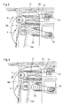
- 5 serves in the present application like FIG. 4 to explain the prior art, while Figure 6 for further explanation an arrangement according to the invention.
- the same reference numerals are used in Figures 4, 5 and 6 to indicate the already in connection with the figures 1 to 3 described components. Accordingly, it is also shown in FIG. Fig. 5 shows the stripping roller 17 and that part of the cloth 100 which with the roller 17 forms the respective reversal area.
- Reference numeral 70 indicates in each of these figures on parts of the machine frame, which in both cases one Drive motor 72 for the roller 17 carries. 5 contains the machine frame 70 the cover 33 (according to FIG. 4), which is not shown in more detail. The Motor 72 is connected to roller 17 via a belt 74.
- take-off or scraping roller 76 Also mounted on the machine frame is one in each of these arrangements so-called take-off or scraping roller 76 and a respective drive motor 78.
- This roller is well known to the person skilled in the art from the prior art, and it also exercises in both versions shown their ordinary function and therefore not described in detail.
- a drive not shown, moves the riser cloth up an endless path in the direction of arrow A (again clockwise).
- On the riser cloth cross bars are attached with steel pins 101 attached to them.
- the motor 72 drives - as already in FIG. 4 described - the roller 17 in the direction of rotation indicated by the arrow B, i.e. also clockwise.
- the roller 17 accordingly rotates in the opposite direction to the cloth in the work area AB and throws excess fiber material directly into the store (not shown in Figures 5 and 6). This improves the mixing, but at most also leads to increased processing of the fibers and possibly to nits.
- the design of the roller 17 (in particular its set) and the Suitable speeds of the roller 17 are also known to the person skilled in the art, see in this regard the description of FIG. 9.
- the motor 72 drives the Roller 17 of the same construction in the direction of rotation indicated by arrow C, i.e. counterclockwise.
- the roller 17 therefore rotates in the same direction as the cloth in the work area AB and helps accordingly, the fiber material carried by the cloth to promote.
- With a suitable selection of the speed of the roller relative to Speed of the cross bars of the cloth it is now possible to open an additional one of the transported material.
- the roller 17 still throws excess Fiber material back into the memory, but no longer directly but by transportation over the part of the roller circumference which is removed from the cloth.
- the design of the roller 17 and the speed of the roller can be optimized by means of tests to optimize the effects mentioned.
- FIG. 7 The schematic representation of the device according to the invention is similar to the mixer known from FIG. 4 with the associated fiber removal device.
- the few design changes according to the invention bring about a significant improvement in the functioning and conveying capacity of the system.
- the same components therefore have the same reference symbols as in FIG. 4.
- the mode of operation of the cloth 100 and the memory 32 is also the same here.
- the stripping roller rotates in the opposite direction, ie in the counterclockwise direction.
- the stripping roller 17 loses its original function of “stripping back” or “throwing back” and gains an actually new function for it: it helps the cloth 100 to “convey” fiber material: in the working area AB, the fiber material conveyed by the cloth 100 either remains on the cloth and is transported over the upper reversing area, or else, it is captured by the counter-rotating roller 17.
- the material captured by the stripping roller 17 is not thrown back, but is conveyed or thrown in the transport direction of the cloth.
- the return means then conveys the detected material in the working area AB in two directions (shown in the figure by two connected arrows).
- the fibers are either conveyed into the upper reversing area in the transport direction of the cloth, or they follow the rotating return medium surface and are conveyed back over the return medium into the storage or mixing chamber 32.
- the fiber flakes captured by the return medium surface are first thrown against the cover 35 or 36 by centrifugal force.
- the air flow generated by the rotating return means then pulls the fiber flakes in the direction of rotation of the return means. Until the fiber flakes transported by the air flow get back into the storage 32, they can be flung back and forth several times between the cover and the return medium surface.
- This effect according to the invention is favored by the fact that a suitable deflecting means is present above the stripping means (for example, as shown in FIG. 7, a deflecting plate 35).
- the presence of a cover or a baffle can be particularly important for the construction of the air flow mentioned.
- the baffle or the adapted cover must be positioned at a suitable distance from the return medium surface so that a suitable air flow can arise. The most suitable distance is best determined in experiments.
- the baffle 35 also causes the fiber material to be returned to be transported between the return medium surface and the baffle in the direction of the accumulator and does not reach the reversal area of the cloth.
- the baffle 35 in FIG. 7 has a particularly favorable shape because it follows the return medium surface at a suitable distance, so to speak. This results in both an optimal air flow and an ideal guidance of the fiber flakes back into the storage or mixing chamber 32.
- the shape of the baffle plate can also be selected more easily, however, and can have any shape.
- the baffle plate claimed in the claims therefore does not have to have a specific shape, but only has the function of conveying a portion of the fiber material captured by the return means back into the store.
- the device according to the invention preferably also has a “nose” 36. This nose also improves and supports the action of the baffle 35 (deflecting the flakes in the desired direction and generating an air flow).
- a further advantage of the invention is that the fiber material conveyed or spun over the return means undergoes a further treatment, as it were.
- the system according to the invention also enables significantly higher delivery or throughput quantities of fiber material.
- the setting options, such as the distance between the return medium and the cloth, the distance between the cloth and the take-off roll, and the absolute and relative speeds of the components mentioned have a great influence on the effective production in the system according to the invention.
- the stripping roller (with a diameter of 250 mm) rotates at a speed of 560 revolutions per minute
- the needle slat has an effective diameter of 160 mm and rotates in a range from 21.6 to 216 revolutions per minute
- the take-off roller rotates with it a diameter of 250 mm has a speed of 660 revolutions per minute.
- FIG. 8 shows the invention with a different design of the baffle.
- the cover 33 known from FIG. 4 was only with the guide plate 35 added.
- This guide plate 35 takes over in the arrangement according to FIG Function of the baffle and the nose of Figure 7.
- the guide plate 35 is in its effect is not as favorable as the baffle with the associated nose, but it can also a suitable deflection of the flakes in the desired direction over the Cause repatriation. If it is the arrangement (distance) of the cover or the machine frame for the return means allows, as with the cover 33 in FIG. 8, sufficient air flow can also be generated.
- FIG. 9 shows two possible sets (sheet metal sets) on the stripping roller 17.
- sheet metal sets are also conceivable and usable, for example a set of teeth or needles.
- the dimensions and density of the set e.g. Distance between the sheets and their height
- the dimensions and density of the set are according to the needs adapt.
- the invention accordingly provides a fiber processing machine with a riser cloth, a movable return means that cooperates with the cloth in a predetermined area (work area) and a drive for the return means, wherein the drive can be operated such that the directions of movement of the cloth and of the return means are the same (in synchronism).
- a fiber processing machine has a baffle above the return means, which faces the return means surface at a suitable distance, so that the movement of the return means creates an air flow which, together with the movement of the return means surface, is able to return the excess fiber material over the return means to move the store.
- the fiber processing machine can have a nose above the work area.
- the nose and the deflector merge.
- Said fiber processing machine can have a rotatable return roller (17) as return means.
- This return roller (17) can be provided with a set, preferably a sheet metal set. Arrangements are also conceivable in which the return means consist of several return rollers.
- the fiber processing machine is set in such a way that the speed of the return means on its surface is greater than the speed of the cloth surface, preferably the two means mentioned move according to at least one of the following speed parameters: the surface of the return means moves at a speed between 4 to 8 m / s faster than the surface of the cloth, the surface of the cloth moves at a speed between 0.1 and 3 m / s, the return means has a speed of 5 to 10 m / s, preferably 7.33 m / s, on its surface.
- the peripheral speed of the take-off roller is preferably greater than the speed of the cloth.
- the peripheral speed of the take-off roller is preferably 7 to 10 m / s, preferably 8.63 m / s.
- a pipeline (11) with an air flow as the transport device (6) can be provided for the further transport of the fibers.
- the fiber processing machine mentioned can - but does not have to - be a mixer (3), in particular a shaft mixer, a bale mixer or a mixer opener.
- at least one of the two following positions can be varied: the position and the distance from the return means, in particular the return roller, to the cloth, the distance and the position of the removal roller to the cloth, these positions can preferably be set during operation of the fiber processing machine.
- the working area can be in the reversal area of the riser cloth.
- the invention obviously also encompasses a method for fiber processing machines which contain at least one riser cloth and at least one movable return means, wherein the return means or the cooperating with the riser cloth in a predetermined area (work area) and a drive for the return means is present, the Drive for the or the return means is actuated such that the directions of movement of the cloth and the / the return means are the same (in synchronism) in the work area.
- the invention is not restricted to these examples. As mentioned earlier, there are others Recycle means known in the art, e.g. based on the in the Introduction mentioned writings was explained. Arrangements are also conceivable where the return means consists of several return rollers. Arrangements with Several return rollers are, for example, the B3 / 4 mixing bale opener or the Mixer opener B3 / 3 of the applicant known. Known return media can be according to of the present invention. The invention is not on application restricted in a mixer. Likewise, others can instead of the cloth suitable transport devices, in particular other conveyor belts, are used become. There are combinations of the individual versions as well as other forms and designs of the device according to the invention possible.
Landscapes
- Engineering & Computer Science (AREA)
- Textile Engineering (AREA)
- Preliminary Treatment Of Fibers (AREA)
Abstract
Description
- Figur 1
- eine Spinnereivorbereitungseinrichtung in Form einer Putzereianlage in schematischer Darstellung,
- Figur 2
- einen Schachtmischer im Schnitt mit nachgeordneter Ausscheideeinrichtung gemäss EP-A-874070,
- Figur 3
- ein Steiglattentuch für die Entnahme von Faserflocken aus dem Mischer,
- Figur 4
- eine schematische Darstellung einer Faserentnahmevorrichtung gemäss dem Stand der Technik,
- Figur 5
- ein Detail im Umkehrbereich einer Anordnung gemäss Figur 4 bzw. eine Modifikation der Anordnung gemäss Figur 2,
- Figur 6
- ein Detail im Umkehrbereich einer Anordnung gemäss der vorliegenden Erfindung,
- Figur 7
- eine schematische Darstellung einer Faserentnahmevorrichtung gemäss der vorliegenden Erfindung
- Figur 8
- eine mögliche Ausgestaltung eines Erfindungsmerkmals
- Figur 9
- Ein mögliches Rückführmittel mit unterschiedlichen Garnituren (Blechgarnituren)
Um die Fördermenge an Fasern zu steuern besitzt die in Figur 4 gezeigte Misch- und Faserentnahmevorrichtung zwei Möglichkeiten: Erstens, sowohl das Transportband 30, als auch das Tuch 100 stoppen, zum Beispiel wegen der folgenden Maschine. Zweitens, die Niveauregulierung der Faserentnahmevorrichtung steuert die Fördermenge. Dazu besitzt der Speicher ab einer gewissen Höhe die Sensoren 34. Erreicht die mehr oder weniger rotierende Fasermasse im Speicher 32 die Höhe des höchsten Sensors (z.B. eine Lichtschranke), so ist der Speicher 32 voll: Das Transportband 30 stoppt die Zulieferung, während das Tuch 100 weiterfördert. Das Tuch 100 kann somit kein weiteres Fasermaterial aus dem horizontalen Schichten entnehmen und fördert daher Faserflocken aus dem Speicher 32 weiter. Dadurch nimmt die im Speicher 32 vorhanden Fasermenge ab. Unterschreitet die gespeicherte Fasermenge die Höhe des untersten Sensors, so schaltet sich das Transportband 30 wieder ein. Nebst diesen beiden Möglichkeiten (quasi "Stop and go" der Endlosbänder) zur Steuerung der Fördermenge besitzen diese traditionellen Anlagen noch weitere Einstellmöglichkeiten zum Dosieren der Fördermenge. Dazu gehört die Möglichkeit den Abstand zwischen Rückstreifwalze 17 und Tuch 100 oder zwischen Abstreichwalze 76 und Tuch 100 zu variieren, sowie den relativen Geschwindigkeitsunterschied zwischen der Oberfläche bzw. Zähne der Rückstreifwalze und der Tuchoberfläche zu verändern. Diese Einstellungen werden bei traditionellen Anlagen eigentlich nur einmal vorgenommen und während dem Betrieb der Anlage nicht mehr verändert. Ein Nachteil der traditionellen Anlagen ist, dass sich durch Anpassen dieser Einstellmöglichkeiten die Fördermenge nur begrenzt steigern lässt. Die genannten Einstellmöglichkeiten bestehen auch bei der erfindungsgemässen Vorrichtung, nur dass man dadurch die Fördermenge wesentlich mehr beeinflussen, d.h. steigern kann. Beim Anmeldungsgegenstand ist es aber auch vorgesehen, die genannten Einstellmöglichkeiten während dem Betrieb der Anlage zu verändern.
Auch hier ist die Wirkungsweise des Tuches 100 und des Speichers 32 dieselbe. Im Gegensatz zum Stand der Technik dreht die Rückstreifwalze aber in entgegengesetzter Richtung, d.h. im Gegenuhrzeigersinn. Dadurch verliert die Rückstreifwalze 17 ihre ursprüngliche Funktion des "Rückstreifens" oder "Zurückwerfens" und gewinnt dafür eine eigentlich neue Funktion: Sie hilft dem Tuch 100 Fasermaterial zu "fördern": Im Arbeitsbereich AB bleibt das vom Tuch 100 geförderte Fasermaterial entweder auf dem Tuch und wird über den oberen Umkehrbereich transportiert, oder aber, es wird von der im Gegenuhrzeigersinn drehenden Rückstreifwalze 17 erfasst. Im Gegensatz zu traditionellen Anlagen wird das von der Rückstreifwalze 17 erfasste Material aber nicht zurückgeworfen, sondern in Transportrichtung des Tuches gefördert bzw. geschleudert. Das Rückführmittel befördert anschliessend am Arbeitsbereich AB das erfasste Material in zwei Richtungen (in der Figur durch zwei verbundene Pfeile dargestellt). Die Fasern werden entweder in Transportrichtung des Tuches in den oberen Umkehrbereich gefördert, oder sie folgen der rotierenden Rückführmitteloberfläche und werden über dem Rückführmittel hinweg zurück in den Speicher bzw. Mischkammer 32 gefördert. Bei diesem zweiten Transportweg werden die von der Rückführmitteloberfläche erfassten Faserflocken zuerst durch die Fliehkraft gegen die Abdeckung 35 oder 36 geschleudert. Der vom rotierenden Rückführmittel erzeugte Luftstrom zieht dann die Faserflocken in Rotationsrichtung des Rückführmittels mit. Bis die vom Luftstrom transportierten Faserflocken zurück in den Speicher 32 gelangen, können sie mehrere Male zwischen Abdeckung und Rückführmitteloberfläche hin und her geschleudert werden. Diese erfindungsgemässe Wirkung wird dadurch begünstigt, dass oberhalb des Rückstreifmittels ein geeignetes Ablenkmittel vorhanden ist (zum Beispiel wie in Figur 7 dargestellt, ein Ablenkblech 35). Besonders für den Aufbau der erwähnten Luftströmung kann die Anwesenheit einer Abdeckung bzw. eines Ablenkbleches wichtig sein. Das Ablenkblech oder die angepasste Abdeckung muss in einem geeigneten Abstand zur Rückführmitteloberfläche positioniert sein, damit ein geeigneter Luftstrom entstehen kann. Der geeignetste Abstand wird am besten in Versuchen ermittelt. Das Ablenkblech 35 bewirkt auch, dass das zurück zu befördernde Fasermaterial zwischen Rückführmitteloberfläche und Ablenkblech in Richtung des Speicher transportiert wird und nicht in den Umkehrbereich des Tuches gelangt. Das Ablenkblech 35 in Figur 7 ist besonders günstig geformt, weil es sozusagen der Rückführmitteloberfläche im geeigneten Abstand folgt. Dies bewirkt sowohl eine optimale Luftströmung, als auch eine ideale Lenkung der Faserflocken zurück in den Speicher bzw. Mischkammer 32. Die Formgebung des Ablenkbleches kann aber auch einfacher gewählt werden ev. eine beliebige Form aufweisen. Eventuell sich an bestehenden Anlagen auch nur kleinere oder sogar gar keine Modifikationen an den Abdeckungen bzw. Maschinengestellen (siehe Figur 5, Komponente 70) notwendig, um ein erfindungsgemässes Ablenkblech darzustellen. Das in den Patentansprüchen beanspruchte Ablenkblech muss daher keine bestimmte Form aufweisen, sondern nur die Funktion erfüllen, einen Teil des von dem Rückführmittel erfassten Fasermaterial zurück in den Speicher zu befördern. Um das Aufteilen der transportierten Fasermenge in zwei Massenströme zu verbessern, weist die erfindungsgemässe Vorrichtung vorzugsweise auch eine "Nase" 36 auf. Diese Nase verbessert und unterstützt auch die Wirkung des Ablenkbleches 35 (Ablenkung der Flokken in die gewünschte Richtung und Erzeugung einer Luftströmung).
Ein weiterer Vorteil der Erfindung ist, dass das über das Rückführmittel hinweg geförderte bzw. geschleuderte Fasermaterial quasi eine weitere Behandlung erfährt. Dadurch, dass sich das Material zwischen der Garnitur des Rückführmittels und der Abdeckung mehrmals hin und her bewegt, wird das Material besser aufgelöst. Speziell die weiter vorne erwähnten Klumpen werden so eliminiert. In den Speicher bzw. Mischkammer 32 werden so kleinere Flocken zurückgeführt. Mit der erfindungsgemässen Anlage erhält man somit eine bessere Auflösung der Flocken und eine bessere Durchmischung.
Nebst der verbesserten Leistung des Mischers bezüglich Durchmischung, Auflösung und Flockengrösse sind mit der erfindungsgemässen Anlage auch merklich höhere Förder- bzw. Durchsatzmengen an Fasermaterial möglich. Die Einstellmöglichkeiten wie Abstand Rückführmittel - Tuch, Abstand Tuch - Abnehmerwalze, sowie absolute wie relative Geschwindigkeiten der genannten Komponenten haben bei der erfindungsgemässen Anlage ein hohen Einfluss auf die effektive Produktion. Bevorzugterweise dreht sich beim Erfindungsgegenstand die Rückstreifwalze (mit einem Durchmesser von 250 mm) mit einer Drehzahl von 560 Umdrehungen pro Minute, das Nadellattentuch besitzt einen Wirkdurchmesser von 160 mm und dreht sich in einem Bereich von 21.6 bis 216 Umdrehungen pro Minute, während die Abnahmewalze mit eine Durchmesser von 250 mm eine Drehzahl von 660 Umdrehungen pro Minute hat.
Die Gefahr einer Verstopfung im oberen Umkehrbereich bei erhöhter Förder- und Durchsatzmenge besteht bei der genannten Drehzahl des Abnehmers nicht. Allfällig wäre in einem solchen Fall die Drehzahl zu erhöhen.
Diese Faserverarbeitungsmaschine weist oberhalb des Rückführmittels ein Ablenkblech auf, welches in einem geeigneten Abstand der Rückführmitteloberfläche gegenübersteht, so dass durch die Bewegung des Rückführmittels eine Luftströmung entsteht, welche zusammen mit der Bewegung der Rückführmitteloberfläche in der Lage ist das überschüssige Fasermaterial über dem Rückführmittel hinweg zurück in den Speicher zu befördern.
Die Faserverarbeitungsmaschine kann oberhalb des Arbeitsbereiches eine Nase aufweisen. In einer bevorzugten Ausführungsform gehen die Nase und das Ablenkblech ineinander über.
Die genannte Faserverarbeitungsmaschine kann als Rückführmittel eine drehbare Rückführwalze (17) aufweisen. Diese Rückführwalze (17) kann mit einer Garnitur versehen sein, vorzugsweise einer Blechgarnitur. Es sind auch Anordnungen vorstellbar, bei denen das Rückführmittel aus mehreren Rückführwalzen bestehen.
Die erfindungsgemässe Faserverarbeitungsmaschine ist derart eingestellt, dass die Geschwindigkeit des Rückführmittels an seiner Oberfläche grösser ist, als die Geschwindigkeit der Tuchoberfläche, vorzugsweise bewegen sich die beiden genannten Mittel nach mindestens einem der folgenden Geschwindigkeitsparameter: Die Oberfläche des Rückführmittels bewegt sich mit einer Geschwindigkeit zwischen 4 bis 8 m/s schneller als die Oberfläche des Tuches, die Tuchoberfläche bewegt sich mit einer Geschwindigkeit zwischen 0.1 und 3 m/s, das Rückführmittel hat eine Geschwindigkeit von 5 bis 10 m/s, vorzugsweise 7.33 m/s, an seiner Oberfläche.
Vorzugsweise ist bei der Faserverarbeitungsmaschine die Umfangsgeschwindigkeit der Abnahmewalze grösser, als die Geschwindigkeit des Tuches. Bevorzugt beträgt die Umfangsgeschwindigkeit der Abnahmewalze 7 bis 10 m/s, vorzugsweise 8.63 m/s.
Bei der beschriebenen Faserverarbeitungsmaschine kann zum Weitertransport der Fasern eine Rohrleitung (11) mit einer Luftströmung als Transporteinrichtung (6) vorgesehen sein.
Die genannte Faserverarbeitungsmaschine kann gemäss den gemachten Ausführungen - muss aber nicht - ein Mischer (3) sein, insbesondere ein Schachtmischer, ein Mischballenöffner oder ein Mischöffner sein.
Bei der erfindungsgemässen Faserverarbeitungsmaschine lassen sich mindestens eine der zwei folgenden Positionen variieren: Die Position und der Abstand vom Rückführmittel, insbesondere Rückführwalze, zum Tuch, der Abstand und die Position der Abnahmewalze zum Tuch, vorzugsweise lassen sich diese Positionen während dem Betrieb der Faserverarbeitungsmaschine einstellen.
Die Erfindung umfasst offensichtlich auch ein Verfahren für Faserverarbeitungsmaschinen, welche mindestens ein Steiglattentuch und mindestens ein bewegliches Rückführmittel enthalten, wobei das oder die Rückführmittel mit dem Steiglattentuch in einem vorgegebenen Bereich (Arbeitsbereich) zusammenarbeitet und ein Antrieb für das/die Rückführmittel vorhanden ist, wobei der Antrieb für das oder die Rückführmittel derart betätigt wird, dass im Arbeitsbereich die Bewegungsrichtungen des Tuches und des/der Rückführmittel gleich (im Gleichlauf) sind.
Claims (12)
- Faserverarbeitungsmaschine mit einem Steiglattentuch, einem beweglichen Rückführmittel, das mit dem Tuch in einem vorgegebenen Bereich (Arbeitsbereich) zusammenarbeitet und einem Antrieb für das Rückführmittel,
dadurch gekennzeichnet, dass
der Antrieb derart betätigt werden kann, dass im Arbeitsbereich die Bewegungsrichtungen des Tuches und des Rückführmittels gleich (im Gleichlauf) sind. - Faserverarbeitungsmaschine nach Anspruch 1, dadurch gekennzeichnet, dass oberhalb des Rückführmittels ein Ablenkblech vorhanden ist, welches der Rückführmitteloberfläche in einem geeigneten Abstand gegenübersteht, so dass das überschüssige Fasermaterial über dem Rückführmittel hinweg zurück in den Speicher befördert wird.
- Faserverarbeitungsmaschine nach Anspruch 1, dadurch gekennzeichnet, dass oberhalb des Arbeitsbereiches eine Nase vorhanden ist, wobei in einer bevorzugten Ausführungsform die Nase und das Ablenkblech ineinander übergehen.
- Faserverarbeitungsmaschine nach Anspruch 1 oder 2, dadurch gekennzeichnet, dass das Rückführmittel eine drehbare Rückführwalze (17) ist.
- Faserverarbeitungsmaschine nach Anspruch 4, dadurch gekennzeichnet, dass die Rückführwalze (17) mit einer Garnitur versehen ist, vorzugsweise einer Blechgarnitur.
- Faserverarbeitungsmaschine nach den Ansprüchen 1 bis 5, dadurch gekennzeichnet, dass die Geschwindigkeit des Rückführmittels an seiner Oberfläche grösser ist, als die Geschwindigkeit der Tuchoberfläche, vorzugsweise bewegen sich die beiden genannten Mittel nach mindestens einem der folgenden Geschwindigkeitsparameter: Die Oberfläche des Rückführmittels bewegt sich mit einer Geschwindigkeit zwischen 4 bis 8 m/s schneller als die Oberfläche des Tuches, die Tuchoberfläche bewegt sich mit einer Geschwindigkeit zwischen 0.1 und 3 m/s, das Rückführmittel hat eine Geschwindigkeit von 5 bis 10 m/s, vorzugsweise 7.33 m/s, an seiner Oberfläche.
- Faserverarbeitungsmaschine nach den Ansprüchen 1 bis 6, dadurch gekennzeichnet, dass die Umfangsgeschwindigkeit der Abnahmewalze grösser ist, als die Geschwindigkeit des Tuches, vorzugsweise beträgt die Umfangsgeschwindigkeit der Abnahmewalze 7 bis 10 m/s, besonders bevorzugt 8.63 m/s.
- Faserverarbeitungsmaschine nach einem oder mehreren der Ansprüche 1 bis 7,
dadurch gekennzeichnet, dass zum Weitertransport der Fasern eine Rohrleitung (11) mit einer Luftströmung als Transporteinrichtung (6) vorgesehen ist. - Faserverarbeitungsmaschine nach einem oder mehreren der vorangehenden Ansprüche, dadurch gekennzeichnet, dass die Maschine ein Mischer (3), insbesondere ein Schachtmischer, ein Mischballenöffner oder ein Mischöffner ist.
- Faserverarbeitungsmaschine nach einem oder mehreren der vorangehenden Ansprüche, dadurch gekennzeichnet, dass sich mindestens eine der zwei folgenden Positionen variieren lassen: Die Position und der Abstand vom Rückführmittel zum Tuch, der Abstand und die Position der Abnahmewalze zum Tuch, vorzugsweise lassen sich diese Positionen während dem Betrieb der Faserverarbeitungsmaschine einstellen.
- Faserverarbeitungsmaschine nach einem oder mehreren der vorangehenden Ansprüche, dadurch gekennzeichnet, dass sich der Arbeitsbereich im Umkehrbereich des Steiglattentuches befindet.
- Verfahren für Faserverarbeitungsmaschinen, welche Steiglattentücher und mindestens ein bewegliches Rückführmittel enthalten, wobei das oder die Rückführmittel mit dem Steiglattentuch in einem vorgegebenen Bereich (Arbeitsbereich) zusammenarbeitet und ein Antrieb für das/die Rückführmittel vorhanden ist, dadurch gekennzeichnet, dass
der Antrieb für das oder die Rückführmittel derart betätigt wird, dass im Arbeitsbereich die Bewegungsrichtungen des Tuches und des/der Rückführmittel gleich (im Gleichlauf) sind.
Applications Claiming Priority (4)
| Application Number | Priority Date | Filing Date | Title |
|---|---|---|---|
| CH521002000 | 2000-03-20 | ||
| CH5212000 | 2000-03-20 | ||
| DE2000149052 DE10049052A1 (de) | 2000-03-20 | 2000-10-04 | Faserverarbeitungsmaschine |
| DE10049052 | 2000-10-04 |
Publications (1)
| Publication Number | Publication Date |
|---|---|
| EP1136598A1 true EP1136598A1 (de) | 2001-09-26 |
Family
ID=25737504
Family Applications (1)
| Application Number | Title | Priority Date | Filing Date |
|---|---|---|---|
| EP01810226A Withdrawn EP1136598A1 (de) | 2000-03-20 | 2001-03-05 | Faserverarbeitungsmaschine |
Country Status (1)
| Country | Link |
|---|---|
| EP (1) | EP1136598A1 (de) |
Cited By (2)
| Publication number | Priority date | Publication date | Assignee | Title |
|---|---|---|---|---|
| CN105648583A (zh) * | 2016-01-07 | 2016-06-08 | 上海应用技术学院 | 玻璃纤维定量输送机 |
| CN114351297A (zh) * | 2020-10-13 | 2022-04-15 | 里特机械公司 | 纺纱制备机 |
Citations (3)
| Publication number | Priority date | Publication date | Assignee | Title |
|---|---|---|---|---|
| GB995652A (en) * | 1962-04-25 | 1965-06-23 | Cotton Silk & Man Made Fibres | Improvements in or relating to the spinning of textile yarns |
| EP0392869A2 (de) * | 1989-04-14 | 1990-10-17 | James H. Roberson | Vorrichtung und Verfahren zum Faseröffnen, Mischen und zur Regelung des Durchflusses |
| EP0874070A1 (de) * | 1997-04-22 | 1998-10-28 | Maschinenfabrik Rieter Ag | Spinnereivorbereitungseinrichtung |
-
2001
- 2001-03-05 EP EP01810226A patent/EP1136598A1/de not_active Withdrawn
Patent Citations (3)
| Publication number | Priority date | Publication date | Assignee | Title |
|---|---|---|---|---|
| GB995652A (en) * | 1962-04-25 | 1965-06-23 | Cotton Silk & Man Made Fibres | Improvements in or relating to the spinning of textile yarns |
| EP0392869A2 (de) * | 1989-04-14 | 1990-10-17 | James H. Roberson | Vorrichtung und Verfahren zum Faseröffnen, Mischen und zur Regelung des Durchflusses |
| EP0874070A1 (de) * | 1997-04-22 | 1998-10-28 | Maschinenfabrik Rieter Ag | Spinnereivorbereitungseinrichtung |
Cited By (3)
| Publication number | Priority date | Publication date | Assignee | Title |
|---|---|---|---|---|
| CN105648583A (zh) * | 2016-01-07 | 2016-06-08 | 上海应用技术学院 | 玻璃纤维定量输送机 |
| CN105648583B (zh) * | 2016-01-07 | 2017-09-12 | 上海应用技术学院 | 玻璃纤维定量输送机 |
| CN114351297A (zh) * | 2020-10-13 | 2022-04-15 | 里特机械公司 | 纺纱制备机 |
Similar Documents
| Publication | Publication Date | Title |
|---|---|---|
| DE3932282A1 (de) | Vorrichtung zum oeffnen und reinigen von fasergut | |
| DE60206690T2 (de) | Öffner und Öffnungsverfahren für Fasermaterial | |
| EP0872269A2 (de) | Verfahren und Vorrichtung zum Ausfiltern von Fasern aus einem Luftstrom | |
| EP0810309B1 (de) | Anlage zum Verarbeiten von Fasern | |
| DE1685528C3 (de) | Anlage zum automatischen und pneumatischen Beschicken einer Kardengruppe mit flockenförmigem Fasergut | |
| DE2002187A1 (de) | Vorrichtung zur Foerderung von faserfoermigen Stoffen | |
| DE2855311C2 (de) | Vorrichtung zur Verarbeitung von Textilfasergut | |
| DE2217394A1 (de) | Verfahren und Vorrichtung zum Homo gemsieren, Trennen und Reinigen von Faser stoffgemischen | |
| DE1091011B (de) | Vorrichtung zum OEffnen, Reinigen und Mischen von Fasergut | |
| DE3711642C2 (de) | ||
| EP0006970B1 (de) | Vorrichtung zum Auftrennen der Baumwollabgänge einer üblichen Baumwollreinigungsmaschine in Gutfasern und Schmutz | |
| DE2714962A1 (de) | Verfahren und vorrichtung zum abtransport und zerkleinern von randstreifen | |
| DE19716792A1 (de) | Spinnereivorbereitungseinrichtung | |
| EP2922671A1 (de) | Fallschachtanordnung mit zweifacher reinigungseinrichtung, insbesondere für eine vorrichtung zur beleimung von partikeln im zuge der herstellung von werkstoffplatten | |
| CH675129A5 (de) | ||
| DE2720340B2 (de) | Verfahren und Vorrichtung zum Abscheiden von Faserflocken aus einem Transportluftstrom in einen Ablagerungsschacht | |
| EP0475073A1 (de) | Putzereilinie | |
| DE2264299A1 (de) | Vorrichtung zum abscheiden von aufgeloesten faserflocken aus einem foerderluftstrom | |
| EP1913185A1 (de) | Reinigungsvorrichtung für eine textilmaschine. | |
| EP0894878A2 (de) | Flockenreiniger | |
| EP0877104A1 (de) | Vorrichtung zum Behandeln eines Fasergutstroms in einer Faseraufbereitungsanlage | |
| DE10049052A1 (de) | Faserverarbeitungsmaschine | |
| DD297465A5 (de) | Rundbuerste fuer eine gerade kaemmaschine | |
| CH717947A1 (de) | Spinnereivorbereitungsmaschine zum Mischen von Fasern. | |
| DE2601016C2 (de) | Verfahren und Einrichtung zum Reinigen von Filterkästen |
Legal Events
| Date | Code | Title | Description |
|---|---|---|---|
| PUAI | Public reference made under article 153(3) epc to a published international application that has entered the european phase |
Free format text: ORIGINAL CODE: 0009012 |
|
| AK | Designated contracting states |
Kind code of ref document: A1 Designated state(s): AT BE CH LI Kind code of ref document: A1 Designated state(s): AT BE CH CY DE DK ES FI FR GB GR IE IT LI LU MC NL PT SE TR |
|
| AX | Request for extension of the european patent |
Free format text: AL;LT;LV;MK;RO;SI |
|
| 17P | Request for examination filed |
Effective date: 20020318 |
|
| AKX | Designation fees paid | ||
| REG | Reference to a national code |
Ref country code: DE Ref legal event code: 8566 |
|
| RBV | Designated contracting states (corrected) |
Designated state(s): AT BE CH LI |
|
| DBV | Designated contracting states (deleted) | ||
| 17Q | First examination report despatched |
Effective date: 20040226 |
|
| 17Q | First examination report despatched |
Effective date: 20040226 |
|
| GRAP | Despatch of communication of intention to grant a patent |
Free format text: ORIGINAL CODE: EPIDOSNIGR1 |
|
| STAA | Information on the status of an ep patent application or granted ep patent |
Free format text: STATUS: THE APPLICATION IS DEEMED TO BE WITHDRAWN |
|
| 18D | Application deemed to be withdrawn |
Effective date: 20090620 |