EP1136401A2 - Topf für Behältern mit bezüglich der Längsachse versezten Hälsen, insbesondere Vereinzelvorrichtung für Behälter - Google Patents
Topf für Behältern mit bezüglich der Längsachse versezten Hälsen, insbesondere Vereinzelvorrichtung für Behälter Download PDFInfo
- Publication number
- EP1136401A2 EP1136401A2 EP01100877A EP01100877A EP1136401A2 EP 1136401 A2 EP1136401 A2 EP 1136401A2 EP 01100877 A EP01100877 A EP 01100877A EP 01100877 A EP01100877 A EP 01100877A EP 1136401 A2 EP1136401 A2 EP 1136401A2
- Authority
- EP
- European Patent Office
- Prior art keywords
- bowl
- container
- containers
- support
- bowls
- Prior art date
- Legal status (The legal status is an assumption and is not a legal conclusion. Google has not performed a legal analysis and makes no representation as to the accuracy of the status listed.)
- Granted
Links
Images


Classifications
-
- B—PERFORMING OPERATIONS; TRANSPORTING
- B65—CONVEYING; PACKING; STORING; HANDLING THIN OR FILAMENTARY MATERIAL
- B65G—TRANSPORT OR STORAGE DEVICES, e.g. CONVEYORS FOR LOADING OR TIPPING, SHOP CONVEYOR SYSTEMS OR PNEUMATIC TUBE CONVEYORS
- B65G47/00—Article or material-handling devices associated with conveyors; Methods employing such devices
- B65G47/02—Devices for feeding articles or materials to conveyors
- B65G47/04—Devices for feeding articles or materials to conveyors for feeding articles
- B65G47/12—Devices for feeding articles or materials to conveyors for feeding articles from disorderly-arranged article piles or from loose assemblages of articles
- B65G47/14—Devices for feeding articles or materials to conveyors for feeding articles from disorderly-arranged article piles or from loose assemblages of articles arranging or orientating the articles by mechanical or pneumatic means during feeding
- B65G47/1407—Devices for feeding articles or materials to conveyors for feeding articles from disorderly-arranged article piles or from loose assemblages of articles arranging or orientating the articles by mechanical or pneumatic means during feeding the articles being fed from a container, e.g. a bowl
- B65G47/1442—Devices for feeding articles or materials to conveyors for feeding articles from disorderly-arranged article piles or from loose assemblages of articles arranging or orientating the articles by mechanical or pneumatic means during feeding the articles being fed from a container, e.g. a bowl by means of movement of the bottom or a part of the wall of the container
- B65G47/1457—Rotating movement in the plane of the rotating part
-
- B—PERFORMING OPERATIONS; TRANSPORTING
- B65—CONVEYING; PACKING; STORING; HANDLING THIN OR FILAMENTARY MATERIAL
- B65G—TRANSPORT OR STORAGE DEVICES, e.g. CONVEYORS FOR LOADING OR TIPPING, SHOP CONVEYOR SYSTEMS OR PNEUMATIC TUBE CONVEYORS
- B65G2201/00—Indexing codes relating to handling devices, e.g. conveyors, characterised by the type of product or load being conveyed or handled
- B65G2201/02—Articles
- B65G2201/0235—Containers
- B65G2201/0244—Bottles
Definitions
- the present invention relates to a bowl for accommodating containers whose necks are offset relative to a longitudinal axis, especially in a container unscrambling machine.
- unscrambling machines are designed to accept a bulk supply of randomly oriented containers and to place them neck up in the upright position.
- the containers are placed in a recumbent position inside rotary bowls whose bottoms consist of a fixed ring.
- the fixed ring has at least one break in it, through which the containers drop into a chute located under the bowl itself.
- the bowl is shaped in such a way that the container always falls neck up.
- a support that acts as a pivot for the neck about which the container rotates.
- the neck of the container is offset relative to the longitudinal axis of the container. This is typically the case of large plastic bottles for oils and detergents.
- Patent EP 0856482 describes a solution where a camera/visualisation device 17 is connected to cam means which cause a horizontal surface to rotate. This significantly increases the cost of the machine.
- the top edge of the container bottom is the point that is furthest away from the centre of rotation of the container and may jam against the walls of the bowl.
- the aim of the present invention is to overcome the above mentioned disadvantages by providing a container bowl that allows containers whose necks are offset relative to a longitudinal axis to be tipped into the upright position without jamming.
- the bowl for accommodating containers whose necks are offset relative to a longitudinal axis
- the bowl according to the present invention being made as characterised in the claims below and in particular characterised in that it comprises at least one support that moves between a first position where the container lies horizontal on the bottom of the bowl and a second position where the container is tipped and drops into a chute, said first position forming a section connecting the bowl to the chute that is smaller than the connecting section formed at the second position.
- the numeral 1 indicates a container whose neck is offset relative to a longitudinal axis 1a. This typically is the shape of large plastic bottles used for oils or detergents.
- a container unscrambling machine normally comprises a base structure consisting, for example, of a fixed cylindrical structure positioned with its longitudinal axis vertical or inclined, depending on machine design.
- the base structure acts as container feed hopper and, depending on design, may have inside it a cylinder or a disc that rotates about the fixed cylindrical structure.
- the rotating cylinder there is a fixed cone inside and concentric with the fixed cylindrical structure and with the rotating cylinder.
- the cone is designed to receive the containers and to direct them towards the walls of the rotating cylinder where there are means for transferring the containers from a lower level to an upper level.
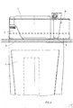
- the rotating cylinder At its upper level, the rotating cylinder has mounted around its circumference a plurality of bowls 2 within which the container is positioned lying in a recumbent position.
- the containers are placed in bulk directly on the rotating disc.
- the bowls 2 designed to receive the containers lying in a recumbent, substantially horizontal, position are mounted around the circumference of the rotating disc. In this case too, as the disc rotates, the containers are transferred from a lower level to an upper level.
- the containers 1 rest on a bottom 3 usually consisting of a ring attached to the fixed base structure of the unscrambling machine. The bottom has at least one break in it, which is not illustrated in the drawings.
- each bowl 2 there is a chute 4 mounted on the outside surface of the rotating cylinder or outside the rotating disc, depending on whether the unscrambling machine is of the type with vertical or inclined axis, respectively.
- the chutes 4 rotate with the corresponding bowls 2 above them and are designed to receive the containers in an upright position.
- the bowls 2 move the containers 1, which are recumbent, to at least one tipping position, corresponding to the point where the bottom 3 has a break in it.
- the chutes 4 communicate with the bowls 2 so that the containers 1 are tipped neck up from the bowls 2 into the chutes 4.
- the bowls 2 comprise at least one support over which the neck of the container is positioned in such a way that when the break in the bottom 3 is reached, the container 1 rotates about its neck in such a way as to fall neck up into the chute 4.
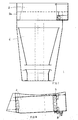
- the bowl 2 comprises a support 5 that moves between a first position where the container lies horizontal on the bottom of the bowl and a second position where the container is tipped and drops into the chute 4.
- the support 5 thus constitutes a mobile end for the section that connects the bowls to the corresponding chutes. Looking in more detail, when the support 5 is in the first position, it forms the end of a connecting section between the bowls and the chutes that is smaller than the section formed when the support is in the second position.
- the bowl may advantageously comprise a rocker arm 6 having a first end mounted on the bowl itself and a second end attached to the support 5, allowing the support 5 to rotate about the first end of the rocker arm.
- the support rotates under the weight of the container when the latter reaches the break in the bottom 3, that is to say, when the container is close to the tipping position.
- the rocker arm may advantageously comprise means 7 for adjusting the stroke of the support according to the weight of the container.
- the adjustment means 7 comprise a threaded element mounted on the rocker arm and having one end that interferes with the bowl.
- the bowl 2 may advantageously comprise a stop element 8 that is connected to, and acts in conjunction with, the support.
- the stop element extends from the bowl and, as the containers move, interacts with a fixed control, which is not illustrated, located close to the tipping position.
- the fixed control may consist, for example, of a cam attached to the inside walls of the fixed cylindrical structure which by interacting with the stop element 8, causes the container support 5 to rotate.
- the bowl 2 further comprises an indentation 2a made in a wall of the bowl itself and shaped in such a way as to enable the container 1 to be tipped and in particular in such a way as not to interfere with the end 1b of the container.
- the container unscrambling machine comprising the bowl 2 according to the present invention has important advantages.
Landscapes
- Engineering & Computer Science (AREA)
- Mechanical Engineering (AREA)
- Feeding Of Articles To Conveyors (AREA)
- Filling Of Jars Or Cans And Processes For Cleaning And Sealing Jars (AREA)
- Sorting Of Articles (AREA)
- Chutes (AREA)
- Packages (AREA)
- Pressure Vessels And Lids Thereof (AREA)
- Blow-Moulding Or Thermoforming Of Plastics Or The Like (AREA)
- Combined Means For Separation Of Solids (AREA)
Applications Claiming Priority (2)
| Application Number | Priority Date | Filing Date | Title |
|---|---|---|---|
| IT2000PR000016A ITPR20000016A1 (it) | 2000-03-15 | 2000-03-15 | Vaschetta di alloggiamento di contenitori provvisti di imboccatura decentrata rispetto ad un asse longitudinale, in particolare in una macch |
| ITPR200016 | 2000-03-15 |
Publications (3)
| Publication Number | Publication Date |
|---|---|
| EP1136401A2 true EP1136401A2 (de) | 2001-09-26 |
| EP1136401A3 EP1136401A3 (de) | 2003-01-02 |
| EP1136401B1 EP1136401B1 (de) | 2004-08-18 |
Family
ID=11453395
Family Applications (1)
| Application Number | Title | Priority Date | Filing Date |
|---|---|---|---|
| EP01100877A Expired - Lifetime EP1136401B1 (de) | 2000-03-15 | 2001-01-16 | Vereinzelungsvorrichtung mit Schüsseln für Behälter mit bezüglich der Längsachse versetzten Hälsen |
Country Status (5)
| Country | Link |
|---|---|
| EP (1) | EP1136401B1 (de) |
| AT (1) | ATE273897T1 (de) |
| DE (1) | DE60104922T2 (de) |
| ES (1) | ES2226984T3 (de) |
| IT (1) | ITPR20000016A1 (de) |
Citations (4)
| Publication number | Priority date | Publication date | Assignee | Title |
|---|---|---|---|---|
| DE3413234A1 (de) | 1983-04-08 | 1984-11-08 | Jaime Marti Barcelona Sala | Vorrichtung zum automatischen aufrichten von behaeltern unterschiedlicher form und groesse |
| EP0347107A1 (de) | 1988-06-13 | 1989-12-20 | Alcan International Limited | Gefüllte Blechkanne |
| EP0540477A1 (de) | 1991-10-28 | 1993-05-05 | Lino Lanfranchi | Verbesserung in einer Behälterpositioniermaschine |
| EP0856482A1 (de) | 1997-01-31 | 1998-08-05 | Jaime Marti Sala | Automatisierte Einheit zum Ausrichten von ungeordnet zugeführten Gegenständen |
Family Cites Families (1)
| Publication number | Priority date | Publication date | Assignee | Title |
|---|---|---|---|---|
| HU227466B1 (en) * | 1998-05-21 | 2011-06-28 | Sala Jaime Marti | Adjustable machine for the vertical orientation and alignment of empty containers |
-
2000
- 2000-03-15 IT IT2000PR000016A patent/ITPR20000016A1/it unknown
-
2001
- 2001-01-16 EP EP01100877A patent/EP1136401B1/de not_active Expired - Lifetime
- 2001-01-16 DE DE60104922T patent/DE60104922T2/de not_active Expired - Fee Related
- 2001-01-16 ES ES01100877T patent/ES2226984T3/es not_active Expired - Lifetime
- 2001-01-16 AT AT01100877T patent/ATE273897T1/de not_active IP Right Cessation
Patent Citations (4)
| Publication number | Priority date | Publication date | Assignee | Title |
|---|---|---|---|---|
| DE3413234A1 (de) | 1983-04-08 | 1984-11-08 | Jaime Marti Barcelona Sala | Vorrichtung zum automatischen aufrichten von behaeltern unterschiedlicher form und groesse |
| EP0347107A1 (de) | 1988-06-13 | 1989-12-20 | Alcan International Limited | Gefüllte Blechkanne |
| EP0540477A1 (de) | 1991-10-28 | 1993-05-05 | Lino Lanfranchi | Verbesserung in einer Behälterpositioniermaschine |
| EP0856482A1 (de) | 1997-01-31 | 1998-08-05 | Jaime Marti Sala | Automatisierte Einheit zum Ausrichten von ungeordnet zugeführten Gegenständen |
Also Published As
| Publication number | Publication date |
|---|---|
| EP1136401B1 (de) | 2004-08-18 |
| ATE273897T1 (de) | 2004-09-15 |
| ITPR20000016A0 (it) | 2000-03-15 |
| EP1136401A3 (de) | 2003-01-02 |
| DE60104922T2 (de) | 2005-08-18 |
| ES2226984T3 (es) | 2005-04-01 |
| ITPR20000016A1 (it) | 2001-09-15 |
| DE60104922D1 (de) | 2004-09-23 |
Similar Documents
| Publication | Publication Date | Title |
|---|---|---|
| US9113729B2 (en) | Stirrer or spoon dispenser for beverage dispensing machines | |
| MXPA05005421A (es) | Maquina alimentadora-dispensadora de recipientes y articulos alargados en general. | |
| US8333052B2 (en) | Machine for filling capsules with pharmaceutical products | |
| EP1142807B1 (de) | Vorrichtung für Maschinen zum Umordnen von Behältern, mit automatischen Mitteln zum Ausrichten und Abwerfen eines empfangenen Behälters | |
| CN100471773C (zh) | 通过使用包括多个隔间的下落槽扶正和排列物品的设备 | |
| EP1136401B1 (de) | Vereinzelungsvorrichtung mit Schüsseln für Behälter mit bezüglich der Längsachse versetzten Hälsen | |
| US6286717B1 (en) | Product-discharging device for a product supply system | |
| US8359815B2 (en) | Machine for filling capsules with pharmaceutical products | |
| EP1209103B1 (de) | Maschine zum Orientieren und Ausrichten von Kunststoffbehältern unterschiedlicher Grösse | |
| EP0540477B1 (de) | Verbesserung in einer Behälterpositioniermaschine | |
| US6591964B1 (en) | Machine for orienting containers | |
| JPH04371415A (ja) | チューブ容器整列装置 | |
| EP0630816B1 (de) | Verfahren zum Dosieren körnigen Materials oder ähnlicher Gegenstände und eine Vorrichtung zur Durchführung des Verfahrens | |
| US6478140B2 (en) | Safety device for machines for aligning containers, in particular polyethylene bottles | |
| EP3813603B1 (de) | Vorrichtung zum verteilen von kapseln mit schüttladung | |
| GB2254319A (en) | Dispensing apparatus | |
| JPH08310642A (ja) | 薬剤の払出し方法およびその装置 | |
| JPH0620231Y2 (ja) | 自動販売機のカップ搬出装置 | |
| JP5225861B2 (ja) | 飲料販売機用のカップコンベア兼カップホルダ装置 | |
| JP5225861B6 (ja) | 飲料販売機用のカップコンベア兼カップホルダ装置 | |
| KR0124678Y1 (ko) | 컵 반출장치 | |
| JPH0617681Y2 (ja) | 充填物の自動反転排出装置 | |
| WO1997025264A1 (en) | Apparatus for stacking frustoconical cup-shaped articles | |
| KR20000042545A (ko) | 자동판매기 | |
| JPH0157004B2 (de) |
Legal Events
| Date | Code | Title | Description |
|---|---|---|---|
| PUAI | Public reference made under article 153(3) epc to a published international application that has entered the european phase |
Free format text: ORIGINAL CODE: 0009012 |
|
| AK | Designated contracting states |
Kind code of ref document: A2 Designated state(s): AT BE CH CY DE DK ES FI FR GB GR IE IT LI LU MC NL PT SE TR |
|
| AX | Request for extension of the european patent |
Free format text: AL;LT;LV;MK;RO;SI |
|
| PUAL | Search report despatched |
Free format text: ORIGINAL CODE: 0009013 |
|
| AK | Designated contracting states |
Kind code of ref document: A3 Designated state(s): AT BE CH CY DE DK ES FI FR GB GR IE IT LI LU MC NL PT SE TR |
|
| AX | Request for extension of the european patent |
Free format text: AL;LT;LV;MK;RO;SI |
|
| 17P | Request for examination filed |
Effective date: 20030206 |
|
| 17Q | First examination report despatched |
Effective date: 20030403 |
|
| AKX | Designation fees paid |
Designated state(s): AT BE CH CY DE DK ES FI FR GB GR IE IT LI LU MC NL PT SE TR |
|
| RTI1 | Title (correction) |
Free format text: UNSCRAMBLING MACHINE WITH BOWLS FOR ACCOMMODATING CONTAINERS WHOSE NECKS ARE OFFSET RELATIVE TO A LONGITUDINAL AXIS |
|
| GRAP | Despatch of communication of intention to grant a patent |
Free format text: ORIGINAL CODE: EPIDOSNIGR1 |
|
| GRAS | Grant fee paid |
Free format text: ORIGINAL CODE: EPIDOSNIGR3 |
|
| GRAA | (expected) grant |
Free format text: ORIGINAL CODE: 0009210 |
|
| AK | Designated contracting states |
Kind code of ref document: B1 Designated state(s): AT BE CH CY DE DK ES FI FR GB GR IE IT LI LU MC NL PT SE TR |
|
| PG25 | Lapsed in a contracting state [announced via postgrant information from national office to epo] |
Ref country code: FI Free format text: LAPSE BECAUSE OF FAILURE TO SUBMIT A TRANSLATION OF THE DESCRIPTION OR TO PAY THE FEE WITHIN THE PRESCRIBED TIME-LIMIT Effective date: 20040818 Ref country code: TR Free format text: LAPSE BECAUSE OF FAILURE TO SUBMIT A TRANSLATION OF THE DESCRIPTION OR TO PAY THE FEE WITHIN THE PRESCRIBED TIME-LIMIT Effective date: 20040818 Ref country code: BE Free format text: LAPSE BECAUSE OF FAILURE TO SUBMIT A TRANSLATION OF THE DESCRIPTION OR TO PAY THE FEE WITHIN THE PRESCRIBED TIME-LIMIT Effective date: 20040818 Ref country code: CH Free format text: LAPSE BECAUSE OF FAILURE TO SUBMIT A TRANSLATION OF THE DESCRIPTION OR TO PAY THE FEE WITHIN THE PRESCRIBED TIME-LIMIT Effective date: 20040818 Ref country code: AT Free format text: LAPSE BECAUSE OF FAILURE TO SUBMIT A TRANSLATION OF THE DESCRIPTION OR TO PAY THE FEE WITHIN THE PRESCRIBED TIME-LIMIT Effective date: 20040818 Ref country code: NL Free format text: LAPSE BECAUSE OF FAILURE TO SUBMIT A TRANSLATION OF THE DESCRIPTION OR TO PAY THE FEE WITHIN THE PRESCRIBED TIME-LIMIT Effective date: 20040818 Ref country code: LI Free format text: LAPSE BECAUSE OF FAILURE TO SUBMIT A TRANSLATION OF THE DESCRIPTION OR TO PAY THE FEE WITHIN THE PRESCRIBED TIME-LIMIT Effective date: 20040818 |
|
| REG | Reference to a national code |
Ref country code: GB Ref legal event code: FG4D |
|
| REG | Reference to a national code |
Ref country code: CH Ref legal event code: EP |
|
| REG | Reference to a national code |
Ref country code: IE Ref legal event code: FG4D |
|
| REF | Corresponds to: |
Ref document number: 60104922 Country of ref document: DE Date of ref document: 20040923 Kind code of ref document: P |
|
| PG25 | Lapsed in a contracting state [announced via postgrant information from national office to epo] |
Ref country code: SE Free format text: LAPSE BECAUSE OF FAILURE TO SUBMIT A TRANSLATION OF THE DESCRIPTION OR TO PAY THE FEE WITHIN THE PRESCRIBED TIME-LIMIT Effective date: 20041118 Ref country code: DK Free format text: LAPSE BECAUSE OF FAILURE TO SUBMIT A TRANSLATION OF THE DESCRIPTION OR TO PAY THE FEE WITHIN THE PRESCRIBED TIME-LIMIT Effective date: 20041118 Ref country code: GR Free format text: LAPSE BECAUSE OF FAILURE TO SUBMIT A TRANSLATION OF THE DESCRIPTION OR TO PAY THE FEE WITHIN THE PRESCRIBED TIME-LIMIT Effective date: 20041118 |
|
| PG25 | Lapsed in a contracting state [announced via postgrant information from national office to epo] |
Ref country code: LU Free format text: LAPSE BECAUSE OF NON-PAYMENT OF DUE FEES Effective date: 20050116 Ref country code: CY Free format text: LAPSE BECAUSE OF FAILURE TO SUBMIT A TRANSLATION OF THE DESCRIPTION OR TO PAY THE FEE WITHIN THE PRESCRIBED TIME-LIMIT Effective date: 20050116 Ref country code: IT Free format text: LAPSE BECAUSE OF NON-PAYMENT OF DUE FEES Effective date: 20050116 |
|
| PG25 | Lapsed in a contracting state [announced via postgrant information from national office to epo] |
Ref country code: IE Free format text: LAPSE BECAUSE OF NON-PAYMENT OF DUE FEES Effective date: 20050117 |
|
| PG25 | Lapsed in a contracting state [announced via postgrant information from national office to epo] |
Ref country code: MC Free format text: LAPSE BECAUSE OF NON-PAYMENT OF DUE FEES Effective date: 20050131 |
|
| NLV1 | Nl: lapsed or annulled due to failure to fulfill the requirements of art. 29p and 29m of the patents act | ||
| REG | Reference to a national code |
Ref country code: CH Ref legal event code: PL |
|
| REG | Reference to a national code |
Ref country code: ES Ref legal event code: FG2A Ref document number: 2226984 Country of ref document: ES Kind code of ref document: T3 |
|
| PLBE | No opposition filed within time limit |
Free format text: ORIGINAL CODE: 0009261 |
|
| STAA | Information on the status of an ep patent application or granted ep patent |
Free format text: STATUS: NO OPPOSITION FILED WITHIN TIME LIMIT |
|
| ET | Fr: translation filed | ||
| 26N | No opposition filed |
Effective date: 20050519 |
|
| REG | Reference to a national code |
Ref country code: IE Ref legal event code: MM4A |
|
| PG25 | Lapsed in a contracting state [announced via postgrant information from national office to epo] |
Ref country code: PT Free format text: LAPSE BECAUSE OF NON-PAYMENT OF DUE FEES Effective date: 20050118 |
|
| PGFP | Annual fee paid to national office [announced via postgrant information from national office to epo] |
Ref country code: DE Payment date: 20080122 Year of fee payment: 8 Ref country code: GB Payment date: 20080124 Year of fee payment: 8 |
|
| PGFP | Annual fee paid to national office [announced via postgrant information from national office to epo] |
Ref country code: FR Payment date: 20080122 Year of fee payment: 8 |
|
| PGRI | Patent reinstated in contracting state [announced from national office to epo] |
Ref country code: IT Effective date: 20090401 |
|
| GBPC | Gb: european patent ceased through non-payment of renewal fee |
Effective date: 20090116 |
|
| PG25 | Lapsed in a contracting state [announced via postgrant information from national office to epo] |
Ref country code: DE Free format text: LAPSE BECAUSE OF NON-PAYMENT OF DUE FEES Effective date: 20090801 |
|
| REG | Reference to a national code |
Ref country code: FR Ref legal event code: ST Effective date: 20091030 |
|
| PG25 | Lapsed in a contracting state [announced via postgrant information from national office to epo] |
Ref country code: GB Free format text: LAPSE BECAUSE OF NON-PAYMENT OF DUE FEES Effective date: 20090116 |
|
| PG25 | Lapsed in a contracting state [announced via postgrant information from national office to epo] |
Ref country code: FR Free format text: LAPSE BECAUSE OF NON-PAYMENT OF DUE FEES Effective date: 20090202 |
|
| PGFP | Annual fee paid to national office [announced via postgrant information from national office to epo] |
Ref country code: IT Payment date: 20120127 Year of fee payment: 12 |
|
| PGFP | Annual fee paid to national office [announced via postgrant information from national office to epo] |
Ref country code: ES Payment date: 20120126 Year of fee payment: 12 |
|
| PG25 | Lapsed in a contracting state [announced via postgrant information from national office to epo] |
Ref country code: IT Free format text: LAPSE BECAUSE OF NON-PAYMENT OF DUE FEES Effective date: 20130116 |
|
| REG | Reference to a national code |
Ref country code: ES Ref legal event code: FD2A Effective date: 20140324 |
|
| PG25 | Lapsed in a contracting state [announced via postgrant information from national office to epo] |
Ref country code: ES Free format text: LAPSE BECAUSE OF NON-PAYMENT OF DUE FEES Effective date: 20130117 |