EP1134903A2 - Memory management method and device for the decoding of convolutional codes - Google Patents
Memory management method and device for the decoding of convolutional codes Download PDFInfo
- Publication number
- EP1134903A2 EP1134903A2 EP01660045A EP01660045A EP1134903A2 EP 1134903 A2 EP1134903 A2 EP 1134903A2 EP 01660045 A EP01660045 A EP 01660045A EP 01660045 A EP01660045 A EP 01660045A EP 1134903 A2 EP1134903 A2 EP 1134903A2
- Authority
- EP
- European Patent Office
- Prior art keywords
- memory
- column
- bit
- rows
- row
- Prior art date
- Legal status (The legal status is an assumption and is not a legal conclusion. Google has not performed a legal analysis and makes no representation as to the accuracy of the status listed.)
- Ceased
Links
Images


Classifications
-
- H—ELECTRICITY
- H03—ELECTRONIC CIRCUITRY
- H03M—CODING; DECODING; CODE CONVERSION IN GENERAL
- H03M13/00—Coding, decoding or code conversion, for error detection or error correction; Coding theory basic assumptions; Coding bounds; Error probability evaluation methods; Channel models; Simulation or testing of codes
- H03M13/65—Purpose and implementation aspects
- H03M13/6502—Reduction of hardware complexity or efficient processing
- H03M13/6505—Memory efficient implementations
-
- H—ELECTRICITY
- H03—ELECTRONIC CIRCUITRY
- H03M—CODING; DECODING; CODE CONVERSION IN GENERAL
- H03M13/00—Coding, decoding or code conversion, for error detection or error correction; Coding theory basic assumptions; Coding bounds; Error probability evaluation methods; Channel models; Simulation or testing of codes
- H03M13/37—Decoding methods or techniques, not specific to the particular type of coding provided for in groups H03M13/03 - H03M13/35
- H03M13/39—Sequence estimation, i.e. using statistical methods for the reconstruction of the original codes
- H03M13/41—Sequence estimation, i.e. using statistical methods for the reconstruction of the original codes using the Viterbi algorithm or Viterbi processors
- H03M13/4107—Sequence estimation, i.e. using statistical methods for the reconstruction of the original codes using the Viterbi algorithm or Viterbi processors implementing add, compare, select [ACS] operations
Definitions
- the present invention relates to a method and device for memory management in digital data transfer, and especially but not necessarily memory management in the decoding of the digital data of convolution codes.
- a received signal also contains noise and channel distortions that cause bit errors, which are then partly corrected using an error correction code.
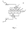
- the transmitted bit stream can be protected against errors, e.g. as depicted in Figure 1, with a corresponding encoder 10, which includes the modulo-2 summing units 11, 12 for forming the convolution code, the shift register 13- 16 for receiving the bit to be coded, input feed for the bit to be coded 17 and the encoded bit's output bits 18, 19.
- bit-stream encoded according to Figure 1 is decoded on reception for example using a Viterbi algorithm. Other decoding means can also be used. In digital data transfer, the bit string received must contain some sort of convolution code, i.e. a code containing memory, so that the Viterbi algorithm can be utilised on reception.
- the encoder's output bits 18,19 are depicted as values of branches 230 - 245.
- the shift register's 13 - 16 elements mentioned in Figure 1 form a status shift, in which the shift register's elements 13 - 15 are the initial status of the Trellis diagram and elements 14 - 16 are the end status of the Trellis diagram, which are reached from the said initial states by feeding a new bit into the encoder's 10 shift register 13 - 16.
- the corresponding 2-bit number for each branch 230 - 245, i.e. each branch state 250 - 265, is compared to the bit pair 18,19 encoded with the encoder 10 in Figure 1.
- the shift register's 13 - 16 bits are now 0101 (from initial state 010 to end state 101), in which case the encoder transmits as the output bits 18 and 19, 10.
- the Trellis diagram states depicted in Figure 2 are utilised in the decoding stage of the data.
- Several path states formed by branch states formed from individual successive state shifts are stored in the decoder's memory. Each bit pattern to be transmitted corresponding to the branch state is compared to received, possibly incorrect, bits. When receiving new bits, the number of state shifts grows, so the memory must be continuously updated by deleting such paths that are not needed for forming the final bit to be decoded.
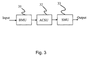
- a so-called Viterbi decoder depicted in Figure 3 which consists of a BMU (Branch Metric Unit) 31, ACSU (Add-Compare-Select Unit) 32 and SMU (Survivor Memory Unit) 33.
- the BMU 31 calculates the metrics, i.e. the measurement of how far the received bit pair is from each, in this case 16, branch state values 250 - 265 corresponding to the Trellis diagram state shifts.
- the so-called Hamming distance i.e. by how many bits the received bits deviate at the time in question from all possible branch metrics corresponding to state shifts, can be used as a measurement.
- Another possible state shift 0011 (from state 001 to state 011) with the same received bit pair 10 would give a metric of 2, because both bits of the received bit pair 10 are now different from the branch value 01.
- the branches 230 - 245 depicting state shifts in Figure 2 always correspond to the possible routes of one received bit pair, of which others are more probable than others and the metric must be calculated for each said branch.
- the ACSU 32 depicted in Figure 3 consists functionally of the Add part, which calculates the cumulative path metric of all paths, i.e. the distance between all possible beginnings and ends of paths; the Compare part, which compares which branch ending in an end state is the more probable choice, i.e. closer to the received bit pair; and the Select part, which selects the more probable branch and stores it to memory.
- the less probable branch is disqualified and if the other branch that reaches the state in question is disqualified, the entire path leading to the state in question can also be deleted from memory as unnecessary. In the following example the less probable option is disqualified for the other branch as well.
- states 001 and 101 both branch off to states 010 and 011.
- the received bit pair was 10.
- the branch value in question has two probable state shifts, i.e. state shift 0010 (from state 001 to state 010 and state shift 1011 (from state 101 to state 011).
- the SMU 33 stores the ACSU's selection data and defines the Trellis diagram final survivor path, which contains the possibly unencoded original bit sequence.
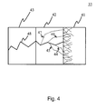
- An ACSU complying with the prior art is the so-called trace back memory 40 depicted in Figure 4, the memory space of which consists of consecutive Trellis diagram states in the form of address books and functionally consists of the following parts.
- a write block 41 in which the decisions coming from the ACSU 32 are received for expressing the Trellis diagram state shifts, and a read region 42, 43, which is further divided into a merge block 42 and a decode block 43. All of the paths 44 - 47 formed by consecutive state shifts that lead to the one same path of decode block 43, i.e.
- survivor path 48 are traced over the merge block 42.
- Paths 44 - 47 are merged for that in which they are the same and the least probable branches are disqualified in accordance with the selections of the ACSU 32, until there is only one path travelling through the merge section, which is formed by several of the consecutive individual branches depicted in Figure 2. Following this, the path in question is decoded, resulting in the original bit sequence.
- the operation of the trace back memory 40 is therefore based on reaching the final decoded bit sequence as content of the decode block 43, by going over all stored paths one by one from the merge block's new end to the old end (trace back) and merging the paths into one survivor path 48.
- the trace back memory has to be of a specific length.
- the length of the trace back memory's merge block has been set to the encoder's rate, i.e. the length of its shift register multiplied by 4 or 5.
- the shift register's length i.e. its rate
- the length of the merge block should be at least 16 - 20 states or cycles long.
- the length of this memory defines both the performance of the decoder in correcting errors and the minimum delay with which the decoded bit, at the earliest, can be received from the memory.
- the lengths of the trace back memory's blocks 41 - 43 can be altered without restriction and there can also be more than one read pointer.
- the time consumed in memory processing in connection with data transfer can be minimised or at least reduced, especially but not necessarily during the reception process and decoding.
- the memory needs to be updated continuously, because more data is continuously being received. This leads to the fact that the memory has to be regularly updated by deleting old data from the memory.
- the speed of this memory update operation can be increased with the invention.
- the present invention is based on the idea that the memory update is done without going over the paths step by step such as in using the trace back method, but instead by copying first memory rows into second memory rows in accordance with the selections of the ASCU, adding the bit column with fixed values as the second memory's first column and making the selection for the decoded bit based on the values of the second memory's last column. Which first memory row is copied to which second memory row is based on information provided by the ACSU.
- Several paths are not merged into one; instead for that part in which the paths are the same, they are shown in the memory several times on different rows. This method of copying between memories leads to the fact that rows at the oldest end of the memory are normally the same, so the original bit can be detected from the memory's last column.
- the paths formed by the state shifts are no longer seen as a bit sequence formed by consecutive states, but instead the last element of each row of the memory bank represents the original unencoded bit.
- the final selection of the decoded bit can be made e.g. by a majority decision, by selecting the bit value that appears numerically the most in the last memory column.
- the invention's goal is achieved with parallel memory updating, which takes place by using two memories side by side by copying a bit row from the first memory (or memory section) to a bit row in the second memory (or memory section).
- the rows in the first memory are old (not updated) and the rows formed in the second memory are new (updated).
- the new fixed bit column is added as the second memory's first column and the old rows of the first memory are copied after the second memory's first column, based on the BMU's information, so that the first memory's first column is the second memory's second column and the first memory's second last column is the second memory's last column.
- the second memory now contains the updated bit rows and the first memory's last column is copied e.g.
- a memory device for the storage of bit rows, characterised in that the memory device consists of a first memory matrix, which contains bit storage places in matrix form where the horizontally consecutive storage places form the first memory rows and the vertically consecutive storage places form the first memory columns; a second memory matrix, which contains bit storage places in matrix form where the horizontally consecutive storage places form the second memory rows and the vertically consecutive storage places form the second memory columns; an input for receiving selection data; addition means for adding fixed-value bits to the set first column as a default column for forming the bit values of the said second memory columns, in which each first column is a column among the said second memory columns; copying means for copying the contents of certain first memory rows row by row to the second memory rows while avoiding copying over the said default column, where the said received selection data affects the placement of the rows regarding which first memory row contents are copied to which second memory row, and for forming the bit values formed in the memory columns; and means for forming the initial bit value from the bit values of the defined second column
- a method for memory management in the memory device characterised in that the method consists of the following stages; selection data formed from the input bits is received; bits are copied from rows of the first memory matrix, which contains bit storage places in matrix form where the horizontally consecutive storage places form the first memory rows and the vertically consecutive storage places form the first memory columns, to rows of the second memory matrix, which contains bit storage places in matrix form where the horizontally consecutive storage places form the second memory rows and the vertically comsecutive storage places form the second memory columns, in accordance with the said received selection data, fixed bit values are added to the second memory matrix to the defined first column for forming the default column from the said fixed bit values, in which each first column is a column among the said second memory columns; the contents of the said first memory rows are copied row by row to the said second memory rows while avoiding copying over the said default column in accordance with the said received selection data, while the said received selection data affects the rows' placement regarding which first memory row content is copied to which second memory row
- a Viterbi decoder for use in decoding convolution codes, which consists of a branch metric unit for receiving the input bit and calculating the metric data, an Add-Compare-Select unit for forming selection data and a survivor memory unit for storing bit sequences, characterised in that the said survivor memory consists of a first memory matrix, which contains bit storage places in matrix form where the horizontally consecutive storage places form the first memory rows and the vertically consecutive storage places form the first memory columns, a second memory matrix, which contains bit storage places in matrix form where the horizontally consecutive storage places form the second memory rows and the vertically consecutive storage places form the second memory columns, an input for receiving selection data from the ACSU, additional equipment for adding fixed-value bits to the set first column as a default column for forming the bit values of the said second memory columns, in which each first column is a column among the said second memory columns, copying means for copying the contents of certain first memory rows row by row to the second memory rows
- an electronic device consisting of equipment for receiving a bit sequence, equipment for forming selection data from the said bit sequence, and survivor memory for storing the bits, characterised in that the said survivor memory consists of a first memory matrix, which contains bit storage places in matrix form where the horizontally consecutive storage places form the first memory rows and the vertically consecutive storage places form the first memory columns, a second memory matrix, which contains bit storage places in matrix form where the horizontally consecutive storage places form the second memory rows and the vertically consecutive storage places form the second memory columns, an input for receiving selection data from the ACSU, additional means for adding fixed-value bits to the set first column as a default column for forming the bit values of the said second memory columns, in which each first column is a column among the said second memory columns, copying means for copying the contents of certain first memory rows row by row to the second memory rows while avoiding copying over the said default column, where the said received selection data affects the placement of the rows regarding which first memory row contents are copied to which
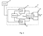
- Figure 5 illustrates a survivor memory 33 corresponding to one performance form of the invention, which consists of two memories 51, 52, two merge matrices 53, 54 and a selection element 56.
- the memories 51 and 52 consist of elements that are one-bit registers and the elements are depicted as memory rows and columns in matrix form.
- the merge matrix 53 is between memories 51 and 52, the merge matrix 54 is between memory matrix 52 and memory matrix 51.
- the merge matrices consist of selection elements that are depicted as selection rows and columns in matrix form.
- Merge matrices 53 and 54 are connected to the ACSU 32, from which merge matrices 53 and 54 receive the selection data based on which the merge matrices decide on the copying of rows between the said memory matrices.
- the change of direction can be performed e.g. by using an arrangement such as that depicted in Figure 5, where the cycle between the memories takes place via the merge matrices.
- Memories 51 and 52 are connected to the transmitter element 56 for selecting the decoded bit after updating from the column after the last column in memory matrices 51 and 52, and for extracting the said bit element from the memory device.
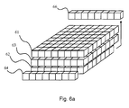
- Figure 6 a illustrates the copying stage between the memory matrices of the memory according to the invention.
- the copying stage from the memory matrix 51 depicted in Figure 5 through merge matrix 53 to memory matrix 52 is identical to the copying taking place from memory matrix 52 through merge matrix 54 to memory matrix 51, so the following describes only the copying stage from memory 51 to memory 52.
- Memory 51 is depicted before updating as matrix 61
- memory 52 after updating is depicted as matrix 62.
- the memories' number of rows is the same as the number of states in the state columns 201, 202 of the Trellis diagram depicted in Figure 2, i.e. in this case there are 8 rows.
- the number of memory columns can be, for example, the length of the shift register of an encoder corresponding to that depicted in Figure 1 multiplied by 4 or 5, but memories with more or less columns than the number in question can also be used.
- the merge matrix 63 is between memory matrices 61 and 62, corresponding to merge matrix 53.
- the first column of memory 62 is the fixed bit column 64.
- the value of the column's elements is determined based on the last bit of the corresponding Trellis diagram state.
- the first column of memory matrix 61 is copied as the second column of memory matrix 62.
- the second column as the third etc., the last column of memory matrix 61 is therefore copied as the column 66 after the last column of memory matrix 62 to the selection element 56, where the final selection of the decoded bit is made.
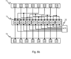
- Figure 6 b illustrates the operation of the merge matrix corresponding to the invention in the form of a single column.
- Column N reference 71
- Column 73 selection column N
- column N+1 reference 72
- the elements of columns 71 and 72 as well as those of the entire memory matrix are efficiently implemented as one-bit registers, e.g. as D flip-flops.
- the copying of the elements of column 71 as elements of column 72 takes place in accordance with the from-row, to-row and state formula column of table 82.
- Each element in column 71 can be copied to two possible places in column 72.
- element D0 in column 71 can be copied to column 72 either as element D0 or D1.
- the selection of the elements to be copied is performed in accordance with the selection data of ACSU 32 in the multiplexes (MUX0 - MUX7) of selection column 73.
- FIG. 7 illustrates a flow chart of the memory's operational principle.
- Old memory refers to memory 61 of Figure 6 and update memory refers to memory 62 of Figure 6.
- the first stage is the formatting of the survivor memory (step 701).
- memories 51, 52 corresponding to those depicted in Figure 5 have to be formatted e.g. by setting the values of all elements to zero.
- the reception of selection signals step 702, in which the merge matrix receives the selection signals necessary for copying the memory rows from the ACSU 32.
- the rows of the old memory are copied to the memory that is to be updated and the fixed column is added as the first column of the update memory (step 703).
- step 702 If reception of the selection signals has ceased (step 702), it is then checked whether or not the update memory's last column 66 has been filled. If the column in question 66 is empty, stage 702 is repeated until reception ceases (step 704) or the memory is full (step 705). When the length of the memory row is e.g. 20 bit, a corresponding number of cycles is needed before the memory's last column is filled. When the column is full (step 705), a majority decision on the final value of the decoded bit is made (step 706) by selecting the value (0 or 1) that appears numerically the most in the column, and sending the value of the bit in question out of the memory. If the majority decision cannot be made, the selection can be made by always selecting one of the values or by randomly selecting one of the values.
- the process moves to stage 702. If reception of the selection signals has ceased (step 704), the process moves to the first memory row of the updated memory. After the encoding of the last bit in the encoder, the encoder's shift register has to be emptied of remaining bits as a signal of ending transmission. This is achieved by feeding as many zero bits as the length of the shift register in question after the last bit. The zero bits are shown on the memory's first row so that as many of the first elements of the row in question are zeroes as is the length of the encoder's shift register used. This row provides the information on which are the last received bits.
- step 707 the process moves to extracting bits from the memory row in question (step 708), the row's last element is extracted by sending the value of the bit in question out of the memory and then the process moves to stage 709. It is now checked whether or not the element last extracted is the last in the row. If this is not so, the process returns to stage 708 until the last element has been extracted from the memory. The process then moves to stage 710 and the reception of transmission is terminated.
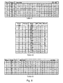
- Figure 8 illustrates the old memory 61 corresponding to Figure 6 and the new updated memory 62 for the first 13 columns.
- Table 81 depicts the memory's content at the present moment before receiving a new bit pair and table 82 depicts the memory's content after the update brought on by the received bit pair.
- Table 81 consists of as many bit rows as the number of Trellis diagram states in the corresponding decoder - in this case 8 rows for each state 000,..., 111.
- table 82 presents a from-row column and a to-row column, which better illustrate the state shift column that depicts all Trellis diagram state shifts 0000, ..., 1111.
- the branch metric of each state shift is illustrated as a column BM, the value of this metric illustrates the measurement by which the received bit pair deviates from the bit pair 250 - 265 of each state shift corresponding to Figure 2.
- the cumulative metric column PM illustrates the overall metric for each state shift, to which all previous branch metric values for that state shift have been summed up.
- the Trellis diagram in Figure 2 depicts all possible state shifts between two consecutive periods of time.
- Column BM therefore shows the metric of the last two consecutive periods of time and column PM shows the metric accumulation from the initial moment to the state shift in question.
- the selection column Select illustrates, with the letters Y and N, the selections performed regarding each state shift based on the column PM.
- the following looks at the copying of rows from Figure 8 in greater detail. As can be seen from the to-row column of table 82, each row can be copied from table 81 to two possible rows in table 83.
- the selection based on which the letter is determined in column 86, is acquired from column PM.
- the cumulative metric for state shift 0000 (from table 81 row 0 to table 83 row 0) is 3 and for state shift 1000 (from table 81 row 4 to table 83 row 0) it is 5. That bit is always selected from the pair, which has a smaller cumulative metric (PM column), and the selected is copied (Select column) from the old memory (table 81) to the new memory (table 83).
- state shift 0000 was selected, because its metric was 3 (state shift 1000's metric was 5), so now the row 0 indicated by table 82 that implements state shift 0000 is copied from the old memory (table 81) to row 0 of the new memory (table 83).
- the survivor memory is formatted (step 701).
- the BMU 31 receives (step 702) the bit pair and compares it to all possible bit pairs corresponding to the state shifts of the Trellis diagram corresponding to Figure 2.
- the ACSU 32 calculates the cumulative metric for all Trellis diagram state shifts 230 - 245 based on the BMU's data. All possible state shifts (0000,..., 1111) are reviewed, and based on the metric thereof the process selects the row that will be copied in the survivor memory 33 from memory matrix 61 to memory matrix 62.
- the merge matrix 53 receives the selection data from the ACSU 32 and based on the received data copies the rows of memory matrix 51 to memory matrix 52, adding the fixed (step703) bit column 64 as the first column in memory 52. It is then checked, whether or not reception has ceased (step 704), and if not, the process moves to step 705 to check if the memory's last column is full. If not, steps 702 - 705 are repeated until the process moves on to step 706, where the decision is made concerning the bit to be selected either by majority decision or, if a majority decision cannot be made, by selecting 0 or 1 either randomly or purposefully, after which the process moves on to step 702.
- step 704 If it is found in step 704 that reception has ceased, the process moves to step 707 and the first row, row 0, of the updated memory matrix 62 is selected. Its first four elements are zeroes, due to the fact that the contents of the encoder that produced the convolution code have been emptied by feeding the said four zeroes as the last bits.
- step 708 the row's last bit is extracted and the process moves on to step 709 to check if the said last bit was the row's last element. If the last element has been extracted from the row, the process moves on to step 710, otherwise steps 708 and 709 are repeated until step 710 is reached, upon which the reception of transmission ceases and the device's operation ceases.
- the length of the memory in both the device according to the invention and of that according to prior art must at least be the length of the previously mentioned encoder's shift register multiplied by 4 or 5. Updating of the memory during the decoding process in a solution according to prior art takes place sequentially (such as from state column 202 to state column 201 in Figure 2), which in this case takes 16 - 20 cycles.
- this can be performed fully parallel to the entire memory during one clock cycle, because the merging of paths during decoding, i.e. the merge operation, of the solution according to prior art is left out.
- the merging is only performed in the last column as the final decision as to the bit value.
- the example presented performs the decoding 16-20 times faster compared to prior art.
- the decoding delay depending on the length of the memory still exists even in the solution according to the invention, i.e. the memory's column 66 must be filled before the first decoded bit can be extracted from the memory.
- a further advantage of the device according to the invention compared to that according to prior art is that when the last bit has been received, the selected row can be extracted, if the bus width so permits, even in one clock cycle.
- K shift register length
- the said memory device can also be used for decoding a convolution code produced by such encoders with a shift register or rate deviating from the values stated above.
Landscapes
- Physics & Mathematics (AREA)
- Probability & Statistics with Applications (AREA)
- Engineering & Computer Science (AREA)
- Theoretical Computer Science (AREA)
- Error Detection And Correction (AREA)
- Detection And Correction Of Errors (AREA)
- Techniques For Improving Reliability Of Storages (AREA)
Abstract
Description
In digital data transfer, the bit string received must contain some sort of convolution code, i.e. a code containing memory, so that the Viterbi algorithm can be utilised on reception. The Viterbi algorithm performs probability decoding using the Trellis diagram to reduce the need for computation. Figure 2 depicts the Trellis diagram 200 formed by the K=4 convolution code, in which the possible initial states 210 - 217 are depicted as
Figure 5 illustrates a
Figure 6 a illustrates the copying stage between the memory matrices of the memory according to the invention. The copying stage from the
Claims (29)
- A memory device for storing bit rows, characterised in that the memory device comprisesa first memory matrix (61), which contains bit storage places in matrix form where the horizontally consecutive storage places form the first memory rows and the vertically consecutive storage places form the first memory columns,a second memory matrix (62), which contains bit storage places in matrix form where the horizontally consecutive storage places form the second memory rows and the vertically consecutive storage places form the second memory columns,an input (55) for receiving selection data,adding means (64) for adding fixed-value bits to the set first column as a default column for forming the bit values of the said second memory columns, in which each first column is a column among the said second memory columns,copying means (63) for copying the contents of certain first memory rows row by row to the second memory rows whilst avoiding copying over the said default column, where the said received selection data affects the placement of the rows regarding which first memory row contents are copied to which second memory row, andforming means (56) for forming the initial bit value from the bit values of the definite second column (66), which second column is a column from the second memory columns.
- A memory device according to Claim 1, characterised in that the first and second memory matrices are part of the same memory.
- A memory device according to Claim 1, characterised in that the first and second memory matrices are physically in separate memories.
- A memory device according to Claim 1, characterised in that the selection data for copying bit rows is received from the Add-Compare-Select unit (32, ACSU).
- A memory device according to Claim 1, characterised in that there are as many said first memory rows as there are first states (210 - 217) corresponding to the set Trellis diagram (200) and as many said second memory rows as there are second states (220 - 227) corresponding to the set Trellis diagram (200).
- A memory device according to Claim 1, characterised in that the said first memory rows are implemented to correspond to each initial state (210 - 217) corresponding to the set Trellis diagram (200).
- A memory device according to Claim 1, characterised in that the said second memory rows are implemented to correspond to each end state (220 - 227) corresponding to the set Trellis diagram (200).
- A memory device according to Claim 1, characterised in that the bits of the fixed value bit column (64) are implemented to correspond to the last bit value of the end state (220 - 227) of the set Trellis diagram (200).
- A memory device according to Claim 1, characterised in that the copying means (63) in turn consists of selection means (72) for selecting the memory rows to be copied in accordance with the received selection data.
- A memory device according to Claim 9, characterised in that the said selection means (72) has been implemented so that from more than one memory row of the said first memory rows one memory row is selected, the contents of which are copied to one memory row of the said second memory rows.
- A memory device according to Claim 1, characterised in that the memory device has been set to repeat the said copying in cycles, whereupon the said copying means (63) for the copying of the contents of certain first memory rows row by row to second memory rows is set to copy from the first memory matrix (61) to the second memory matrix (62) in the first cycle, and is set to copy from the previous cycle's second memory matrix to the previous cycle's first memory matrix on all cycles following the said first cycle.
- A memory device according to Claim 1, characterised in that the said copying means (63) for the copying of the contents of certain first memory rows row by row to second memory rows has been set to copy the contents of a specific memory row in the first memory matrix as the contents of a specific memory row in the second memory matrix in accordance with the state shift (230 - 245) of the corresponding Trellis diagram (200).
- A method for memory management in the memory device, characterised in that the method comprises the following steps;receiving selection data,processing bits with the help of the first memory matrix (61), which contains bit storage places in matrix form where the horizontally consecutive storage places form the first memory rows and the vertically consecutive storage places form the first memory columns, and the second memory matrix (62), which contains bit storage places in matrix form where the horizontally consecutive storage places form the second memory rows and the vertically consecutive storage places form the second memory columns,adding fixed bit values to the second memory matrix (62) to the set first column for forming the default column from the said fixed bit values, in which each first column is a column among the said second memory columns,copying the contents of the said first memory rows row by row to the said second memory rows while avoiding copying over the said default column in accordance with the said received selection data, while the said received selection data affects the rows' placement regarding which first memory row content is copied to which second memory row,forming the initial bit value from the second column bit values, which second column is a column among the second memory columns.
- A method according to Claim 13, characterised in that the said copying of memory rows is implemented so that the memory row to be copied is selected from more than one first memory row.
- A method according to Claim 14, characterised in that the said selection is performed for each second memory row.
- A method according to Claim 13, characterised in that the said selection data contains information on which first memory row is copied as a second memory row.
- A method according to Claim 13, characterised in that the N storage place's bit of the first memory rows is copied to the second memory rows' storage place N+1, in which N is the index number of the storage place.
- A method according to Claim 13, characterised in that the said addition of the fixed bit column is implemented so that the bits of the fixed bit column (64) are added as bits of the second memory rows.
- A method according to Claim 18, characterised in that the said bits form the first bits of the second memory rows.
- A method according to Claim 13, characterised in that the said copying is performed in cycles, in whichin the first cycle, the memory rows of the first memory matrix (61) are copied as memory rows of the second memory matrix (62), the fixed value bit column (64) is added to the second memory matrix as the first column of the said second memory matrix, and the value of the initial bit is formed from the bit values of the definite second memory matrix column, andin every cycle following the first, the previous cycle's second memory matrix is always selected as the first memory matrix (61) and the previous cycle's first memory matrix is always selected as the second memory matrix, the memory rows of the first memory matrix (61) are copied as memory rows of the second memory matrix (62), the fixed value bit column (64) is added to the second memory matrix as the first column of the said second memory matrix, and the value of the initial bit is formedfrom the bit values of the set second memory matrix column.
- A method according to Claim 13, characterised in that if the reception of selection data (step 702) continues, the value of the initial bit is selected as a decision from a bit column (66) formed by the second memory rows (62).
- A method according to Claim 21, characterised in that the said bit column (66) is a bit column formed by the last elements of the said second memory rows (62).
- A method according to Claim 22, characterised in that the value of the initial bit is selected from the bit column's (66) bit values by majority decision, in which case the value of the initial bit is determined by the value that appears numerically the most in the said column.
- A method according to Claim 13, characterised in that when the reception of selection data (step 702) ceases, the value of the initial bit is selected as a decision from a memory row formed by the said second memory rows (62).
- A method according to Claim 24, characterised in that the said memory row is the row implemented to correspond to the first state (220) corresponding to that of the Trellis diagram (200).
- A Viterbi decoder to be used in decoding convolution codes, consisting ofa branch metric unit (31, BMU) for receiving the input bit and calculating the metric data,an Add-Compare-Select unit (32, ACSU) for forming selection data, anda survivor memory unit (33, SMU) for storing bit sequences, characterised in that the said survivor memory (33) further comprisesa first memory matrix (61), which contains bit storage places in matrix form where the horizontally consecutive storage places form the first memory rows and the vertically consecutive storage places form the first memory columns,a second memory matrix (62), which contains bit storage places in matrix form where the horizontally consecutive storage places form the second memory rows and the vertically consecutive storage places form the second memory columns,an input (55) for receiving selection data from the ACSU (32),adding means (64) for adding fixed-value bits to the set first column as a default column for forming the bit values of the said second memory columns, in which each first column is a column among the said second memory columns,copying means (63) for copying the contents of certain first memory rows row by row to the second memory rows while avoiding copying over the said default column, where the said received selection data affects the placement of the rows regarding which first memory row contents are copied to which second memory row; andforming means (56) for forming the initial bit value from the bit values of the set second column (66), in which every second column is a column from the second memory columns.
- An electronic device comprising receiving means for receiving the bit sequence (31),forming means (32) for forming the selection data from the said bit sequence, anda survivor memory unit (33, SMU) for storing bit sequences, characterised in that the said survivor memory (33) further comprisesa first memory matrix (61), which contains bit storage places in matrix form where the horizontally consecutive storage places form the first memory rows and the vertically consecutive storage places form the first memory columns,a second memory matrix (62), which contains bit storage places in matrix form where the horizontally consecutive storage places form the second memory rows and the vertically consecutive storage places form the second memory columns,an input (55) for receiving selection data from the forming equipment (32),adding means (64) for adding fixed-value bits to the set first column as a default column for forming the bit values of the said second memory columns, in which each first column is a column among the said second memory columns,copying means (63) for copying the contents of certain first memory rows row by row to the second memory rows while avoiding copying over the said default column, where the said received selection data affects the placement of the rows regarding which first memory row contents are copied to which second memory row, andforming means (56) for forming the initial bit value from the bit values of the set second column (66), in which every second column is a column from the second memory columns.
- A device according to Claim 27, characterised in that the device is a mobile communications device.
- A device according to Claim 27, characterised in that the device is a computer.
Applications Claiming Priority (2)
| Application Number | Priority Date | Filing Date | Title |
|---|---|---|---|
| FI20000640 | 2000-03-17 | ||
| FI20000640A FI112711B (en) | 2000-03-17 | 2000-03-17 | Method and device for memory management in digital communication |
Publications (2)
| Publication Number | Publication Date |
|---|---|
| EP1134903A2 true EP1134903A2 (en) | 2001-09-19 |
| EP1134903A3 EP1134903A3 (en) | 2003-07-30 |
Family
ID=8557975
Family Applications (1)
| Application Number | Title | Priority Date | Filing Date |
|---|---|---|---|
| EP01660045A Ceased EP1134903A3 (en) | 2000-03-17 | 2001-03-09 | Memory management method and device for the decoding of convolutional codes |
Country Status (4)
| Country | Link |
|---|---|
| US (1) | US6578119B2 (en) |
| EP (1) | EP1134903A3 (en) |
| JP (1) | JP2001331381A (en) |
| FI (1) | FI112711B (en) |
Families Citing this family (4)
| Publication number | Priority date | Publication date | Assignee | Title |
|---|---|---|---|---|
| US20020198725A1 (en) * | 2001-06-21 | 2002-12-26 | International Business Machines Corporation | Method and system for managing a relationship with a venture company |
| TW595117B (en) * | 2003-06-20 | 2004-06-21 | Univ Nat Chiao Tung | Viterbi decoder algorithm applied for memory basis |
| JP4918059B2 (en) * | 2008-03-28 | 2012-04-18 | 京セラ株式会社 | Receiving apparatus and Viterbi decoding method |
| JP2009246490A (en) * | 2008-03-28 | 2009-10-22 | Kyocera Corp | Reception device and viterbi decoding method |
Family Cites Families (5)
| Publication number | Priority date | Publication date | Assignee | Title |
|---|---|---|---|---|
| EP0420339A3 (en) * | 1989-09-29 | 1992-06-03 | N.V. Philips' Gloeilampenfabrieken | Multi-plane random access memory system |
| US5432821A (en) | 1992-12-02 | 1995-07-11 | University Of Southern California | System and method for estimating data sequences in digital transmissions |
| KR100195741B1 (en) | 1996-07-01 | 1999-06-15 | 전주범 | Variable rate Viterbi decoder |
| KR19990035418A (en) | 1997-10-31 | 1999-05-15 | 전주범 | A survival path reverse tracking device for trellis code data |
| US6477680B2 (en) | 1998-06-26 | 2002-11-05 | Agere Systems Inc. | Area-efficient convolutional decoder |
-
2000
- 2000-03-17 FI FI20000640A patent/FI112711B/en not_active IP Right Cessation
-
2001
- 2001-03-09 EP EP01660045A patent/EP1134903A3/en not_active Ceased
- 2001-03-15 US US09/809,122 patent/US6578119B2/en not_active Expired - Lifetime
- 2001-03-16 JP JP2001076595A patent/JP2001331381A/en not_active Withdrawn
Also Published As
| Publication number | Publication date |
|---|---|
| JP2001331381A (en) | 2001-11-30 |
| FI112711B (en) | 2003-12-31 |
| US20010023477A1 (en) | 2001-09-20 |
| FI20000640L (en) | 2001-09-18 |
| US6578119B2 (en) | 2003-06-10 |
| EP1134903A3 (en) | 2003-07-30 |
| FI20000640A0 (en) | 2000-03-17 |
Similar Documents
| Publication | Publication Date | Title |
|---|---|---|
| EP0138598A2 (en) | Error correction apparatus using a viterbi decoder | |
| KR100580160B1 (en) | Modified Backtracking Two-Stage Viterbi Algorithm Decoder | |
| US5802116A (en) | Soft decision Viterbi decoding with large constraint lengths | |
| US4797887A (en) | Sequential decoding method and apparatus | |
| EP0127984A2 (en) | Improvements to apparatus for decoding error-correcting codes | |
| KR100779782B1 (en) | High Speed ACS Unit for Viterbi Decoder | |
| JP2000209106A (en) | Realization by minimum amount of memory of high-speed viterbi decoder | |
| US7035356B1 (en) | Efficient method for traceback decoding of trellis (Viterbi) codes | |
| US6578119B2 (en) | Method and device for memory management in digital data transfer | |
| CN100512020C (en) | Decoding method and decoding device | |
| US11165446B1 (en) | Parallel backtracking in Viterbi decoder | |
| JPH05183448A (en) | Error correction encoding and decoding device | |
| US20110235757A1 (en) | Decoding method and decoding device | |
| US20020112211A1 (en) | Minimum error detection in a viterbi decoder | |
| EP1024603A2 (en) | Method and apparatus to increase the speed of Viterbi decoding | |
| JP3235333B2 (en) | Viterbi decoding method and Viterbi decoding device | |
| JP5370487B2 (en) | Decoding method and decoding apparatus | |
| JPH05335973A (en) | Viterbi decoder and convolutional code decoder | |
| KR100324066B1 (en) | Viterbi decoder | |
| KR100564757B1 (en) | Low Power Viterbi Decoder and Traceback Method | |
| JP3269845B2 (en) | Viterbi decoder | |
| KR100726170B1 (en) | Apparatus and method for viterbi decoding | |
| JP3530451B2 (en) | Viterbi decoding device | |
| JP2002076924A (en) | Viterbi decoder | |
| JPH08139614A (en) | Error correction code / decoding device |
Legal Events
| Date | Code | Title | Description |
|---|---|---|---|
| PUAI | Public reference made under article 153(3) epc to a published international application that has entered the european phase |
Free format text: ORIGINAL CODE: 0009012 |
|
| AK | Designated contracting states |
Kind code of ref document: A2 Designated state(s): AT BE CH CY DE DK ES FI FR GB GR IE IT LI LU MC NL PT SE TR |
|
| AX | Request for extension of the european patent |
Free format text: AL;LT;LV;MK;RO;SI |
|
| PUAL | Search report despatched |
Free format text: ORIGINAL CODE: 0009013 |
|
| AK | Designated contracting states |
Designated state(s): AT BE CH CY DE DK ES FI FR GB GR IE IT LI LU MC NL PT SE TR |
|
| AX | Request for extension of the european patent |
Extension state: AL LT LV MK RO SI |
|
| 17P | Request for examination filed |
Effective date: 20040123 |
|
| AKX | Designation fees paid |
Designated state(s): AT BE CH CY DE DK ES FI FR GB GR IE IT LI LU MC NL PT SE TR |
|
| 17Q | First examination report despatched |
Effective date: 20040921 |
|
| STAA | Information on the status of an ep patent application or granted ep patent |
Free format text: STATUS: THE APPLICATION HAS BEEN REFUSED |
|
| 18R | Application refused |
Effective date: 20070101 |