EP1132162A1 - Verfahren und Vorrichtung zum Giessen von Metall - Google Patents
Verfahren und Vorrichtung zum Giessen von Metall Download PDFInfo
- Publication number
- EP1132162A1 EP1132162A1 EP01301973A EP01301973A EP1132162A1 EP 1132162 A1 EP1132162 A1 EP 1132162A1 EP 01301973 A EP01301973 A EP 01301973A EP 01301973 A EP01301973 A EP 01301973A EP 1132162 A1 EP1132162 A1 EP 1132162A1
- Authority
- EP
- European Patent Office
- Prior art keywords
- metal
- metal material
- slurry
- semi
- solid
- Prior art date
- Legal status (The legal status is an assumption and is not a legal conclusion. Google has not performed a legal analysis and makes no representation as to the accuracy of the status listed.)
- Granted
Links
Images


Classifications
-
- B—PERFORMING OPERATIONS; TRANSPORTING
- B22—CASTING; POWDER METALLURGY
- B22D—CASTING OF METALS; CASTING OF OTHER SUBSTANCES BY THE SAME PROCESSES OR DEVICES
- B22D17/00—Pressure die casting or injection die casting, i.e. casting in which the metal is forced into a mould under high pressure
- B22D17/007—Semi-solid pressure die casting
-
- C—CHEMISTRY; METALLURGY
- C22—METALLURGY; FERROUS OR NON-FERROUS ALLOYS; TREATMENT OF ALLOYS OR NON-FERROUS METALS
- C22C—ALLOYS
- C22C1/00—Making non-ferrous alloys
- C22C1/12—Making non-ferrous alloys by processing in a semi-solid state, e.g. holding the alloy in the solid-liquid phase
Definitions
- This invention relates to a method and apparatus for casting metals including alloys and to a method and apparatus of manufacturing metal materials using a casting apparatus or injection molding machine, and more particularly, this invention relates to a metal casting method and apparatus and a metal material manufacturing method and apparatus, wherein semi-melted and semi-solid metal thixotropy is effectively utilized for each method and apparatus.
- Thixo-casting (semi-melted casting) and rheocasting (semi-solid casting) are known as casting methods utilizing thixotropy, or low viscosity and high fluidity, of a semi-melted and semi-solid metal. These casting methods are implemented by using a semi-melted and semi-solid metal slurry containing a mixture of liquid-phase metal and solid-phase metal.
- thixo-casing a solid metal is heated to form a semi-melted metal slurry and the slurry is then supplied into a mold.
- rheocasting after a solid metal is perfectly melted, the molten metal is cooled to form a semi-solid slurry containing granular crystals and the slurry is then poured into a mold.
- mold filling is improved because it is possible to conduct casting using a metal exhibiting a high solid-phase ratio and low viscosity.
- These methods further have the advantages of enabling (1) a higher yield, (2) molding of large-sized products, (3) suppression of shrinkage cavity formation and improvement in mechanical strength, and (4) molding of thinner products.
- the service life of a mold is prolonged owing to a decreased heat load on the mold.
- ultrafine, uniform non-dendrite crystals (desirably spherical crystals) exist in a semi-melted semi-solid metal in order to effectively utilize the thixotropy of a semi-melted metal and the fluidity of a semi-solid metal.
- the solid metal is simply heated to a semi-melted state or the melted metal is simply cooled to a semi-solid state, almost all metal crystals become dendrite crystals in the semi-melted and semi-solid metal. For this reason, it is impossible to attain sufficient thixotropy of the semi-melted metal and sufficient fluidity of the semi-solid metal.
- a screw extruder is generally used in an injection-molding machine, and a solid metal in the extruder barrel is successively heated while applying a shearing force to the metal to obtain a semi-melted state metal slurry.
- a molten metal is subjected to refrigeration in a holding furnace by contact with a cooling body to obtain a half-melted metal in which a solid phase and a liquid phase coexist.
- the half-melted metal is further cooled in a holding vessel while maintaining the coexisting state, thereby forming a metal slurry.
- the molten metal yields many crystal nuclei when it undergoes refrigeration.
- the crystals become spherical in the vessel, and a desired metal slurry can be produced without use of an expensive extruder generally used in thixo-casting.
- the material cost increase can be controlled, as a metal ingot can be charged into the holding furnace as it is.
- a casting procedure effectively utilizing the fluidity of semi-solid metal can be implemented.
- the present invention has been accomplished, and one object thereof is to provide a metal casting method and apparatus and a metal material manufacturing method and apparatus that can reduce their operation costs and material costs and effectively utilize thixotropy without need of complicated control.
- the present invention provides a casting method comprising a first step of cooling a molten metal to form a metal slurry containing a solid phase, a second step of cooling the metal slurry to form a solid metal material, and a third step of heating the metal material to a semi-melted metal material and supplying it into a mold.
- the second step preferably includes continuously forming metal materials from the metal slurry and cutting the metal materials to a predetermined length.
- This invention further provides a casting apparatus comprising first means for cooling a molten metal to form a metal slurry containing a solid phase and second means for cooling the metal slurry to form a solid metal material. The metal material is then heated to a semi-melted state and the resultant metal material is poured into a mold.
- the second means preferably forms metal materials continuously from the metal slurry and includes a cutting unit for cutting the metal materials to a predetermined length.
- the cutting unit can preferably move along the advancing direction of the metal material and cut the metal material when its velocity relative to the metal material becomes zero.
- This invention further provide a metal material manufacturing method that produces a metal material being heated to a semi-melted state and then supplied into a mold and comprises a first step of cooling a molten metal to form a metal slurry containing a solid phase and a second step of cooling the metal slurry to form a solid metal material.
- the second step preferably includes continuously solidifying the metal slurry into solid metal materials and cutting the metal materials to a predetermined length.
- This invention further provides a metal material manufacturing apparatus that produces a metal material being heated to a semi-melted state and then supplied into a mold and comprises first means for cooling a molten metal to form a metal slurry containing a solid phase and second means for cooling the slurry to form a solid metal material.
- the second means can preferably solidify the metal slurry continuously into solid metal materials and includes a cutting unit for cutting the solid metal materials to a predetermined length.
- a metal slurry excelling in fluidity and containing non-dendrite crystals can easily be produced, without need of complicated control, by rapidly cooling a molten metal into a metal slurry containing non-dendrite crystals in the first step, cooling the slurry into a solid metal material in the second step, and heating the metal material into a semi-melted state.
- the metal slurry thus produced can be supplied into a mold.
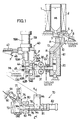
- FIG. 1 shows one embodiment of a casting apparatus according to the invention.
- This casting apparatus is for casting desired products using magnesium alloy (AZ91D) and has a melting pot 1.
- AZ91D magnesium alloy
- the melting pot 1 is covered at its periphery and heated by a melting heater 2 to hold the magnesium alloy in a melted condition or liquid-phase temperature state.
- the melting pot 1 has at its bottom a gate 3 for a molten material.
- the gate 3 is for pouring downward molten magnesium alloy stored in the melting pot 1.
- the gate 3 is bent like a crank and has a switching valve 4 in the middle.
- the switching valve 4 has a slidable valve plunger 5 to open and shut the gate 3 and a valve cylinder 6 to slide the valve plunger 5.
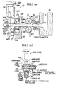
- a cooling unit 10 is placed near the lower area of the melting pot 1. As shown in FIGs. 2(a) and 2(b), the cooling unit 10 has a plurality of guide recesses 11 formed on its surface and a cooling water circulating passage 12 therein. The cooling unit 10 is inclined so the guide recesses 11 face the lower open end of the gate 3.
- Reference number 13 in FIG. 1 represents a cover block that communicates with the lower open end of the gate 3 and has a predetermined space between it and the surface of the cooling unit 10.
- a reservoir 20 having a rapid cooling unit 22, a pair of feed rollers 30 and 31 and a cutting unit 40 are set in the casting apparatus.
- the reservoir 20 is open at its top and is set in position below the cooling unit 10.
- a material forming passage 21 has a circular section and is attached to the reservoir 20.
- the material forming passage 21 is located at the lower part of the reservoir 20, extends horizontally and is open to the side wall of the reservoir 20.
- the rapid cooling unit 22 is set at the end of the passage 21. As shown in FIG. 3(a), the rapid cooling unit 22 comprises a ring jacket 23 surrounding the passage 21 and a spouting nozzle 24 open toward the axial center of the ring jacket 23.
- the feed rollers 30 and 31 are aligned in parallel, one above the other, and have feed recesses 30a and 31a, respectively. These feed recesses have substantially the same radius of curvature as the inside diameter of the material forming passage 21. The distance between the feed recesses 30a and 31a is maintained equal to the inside diameter of the passage 21.
- Each feed roller is coupled with a rotary actuator (not shown) so that the top feed roller 30 rotates clockwise while the bottom feed roller 31 rotates counterclockwise, as shown in FIG. 3(a).
- the cutting unit 40 comprises a main body 41, a fixed damper 42A, a movable clamper 42B and a pair of feed-out rollers 44 and 45.
- the main body 41 of the cutting unit 40 is movably held by a guide rod 46 and reciprocates horizontally along the axial direction of the material forming passage 21 on an extension area of the passage 21.
- a retraction cylinder 47 is placed between the main body 41 and a fixed frame F.
- the retraction cylinder 47 serves as an actuator for allowing the main body 41 to move when an external force acts on the main body 41 in the direction away from the reservoir 20 and causing the main body 41 to return back to a position near the reservoir 20 when the retraction cylinder 47 is operated to extend.
- the fixed clamper 42A and movable clamper 42B are block members having clamp through-holes 49A and 49B that are made open by slits 48A and 48B.
- the clamp through-holes 49A and 49B are formed to have a slightly larger inside diameter than the material forming passage 21.
- the slits 48A and 48B are formed along a plane containing the axis of the clamp through-holes 49A and 49B and adapted to increase or decrease the diameters of the clamp through-holes 49A and 49B by changing the widths of the slits.
- Tapered surfaces 50A and 50B are located at the open ends of the slits 48A and 48B, and rod through-holes 51A and 51B intersect the slits 48A and 48B at positions midway of the slits.
- the tapered surfaces 50A and 508 are inclined so that their widths increase gradually toward the outside.
- the rod through-holes 51A and 51B are parallel to each other and have hemispheric dent portions 52A and 52B at their respective open ends.
- Clamping hydraulic cylinders 53A and 53B and unclamping hydraulic cylinders 54A and 54B are set on the dampers 42A and 42B.
- the clamping hydraulic cylinders 53A and 53B have piston rods 53aA and 53aB inserted via clamp pieces 55 into the rod through-holes 51A and 51B and held by the dampers 42A and 42B because clamp pieces 56 are attached to the dent portions 52A and 52B at the ends of the piston rods 53aA and 53aB.
- the clamp pieces 55 and 56 have spherical parts facing and conforming in radius to the dent portions 52A and 52B of the rod through-holes 51A and 51B. These clamp pieces can reduce the widths of the slits 48A and 48B of the dampers 42A and 42B via the dent portions 52A and 52B when hydraulic pressure is applied to the hydraulic cylinders 53A and 53B. As a result, the diameters of the clamp through-holes 49A and 49B can be made smaller.
- the unclamping cylinders 54A and 54B, with the pointed ends of piston rods 54aA and 54aB opposing the open ends of the slits 48A and 48B, are held by the dampers 42A and 42B via a holding bracket 57.
- An expansion rod 58 is located between the piston rods 54aA and 54aB of the unclamping hydraulic cylinders 54A and 54B and the tapered surfaces 50A and 50B of the slits 48A and 48B.
- the expansion rod 58 is a columnar part attached to the tapered surfaces 50A ad 50B.
- the expansion rod 58 spreads the slits 48A and 48B of the clampers 42A and 42B via the tapered surfaces 50A and 50B, or increases the diameter of the clamp through-holes 49A and 49B.
- the fixed clamper 42A adjusts the axis of the clamp through-hole 49A to coincide with the axis of the material forming passage 21 and is fixed onto the main body 41 of the cutting unit 40 along the vertical above part of the slit 48A.
- the movable clamper 42B is set on a cutting cylinder 59 along the vertical below part of the slit 48B so that its end facing the reservoir 20 abuts on the fixed damper 42A.
- the cutting cylinder 59 and its cylinder body 59b are set on the main body 41 of the cutting unit 40 so that its piston rod 59a is directed vertically downward, and moves the movable clamper 42B in a vertical direction relative to the fixed damper 42A.
- the movable damper 42B stops at its uppermost position so that the axis of the damp through-hole 49B coincides with the axis of the material forming passage 21 or so that the clamp through-hole 49B coincides with the damp through-hole 49A of the fixed damper 42A.
- the feed-out rollers 44 and 45 are set parallel to each other, one above the other, on a roller bracket 60 extending from the movable clamper 42B.
- the feed-out rollers 44 and 45 have feed-out recesses 44a and 45a on their circumferences, and the radius of curvature of each feed-out recess is substantially the same as the inside diameter of the material forming passage 21.
- the interval between the feed-out recesses 44a and 45a is secured to coincide with the inside diameter of the material forming passage 21.
- the feed-out rollers 44 and 45 are linked to rotary actuators (not shown). As shown in FIG. 5(c), the upper fed-out roller 44 rotates clockwise, while the lower feed-out roller 45 rotates counterclockwise.
- Reference numeral 61 in FIG. 1 denotes a guide block that connects between the cover block 13 and the reservoir 20.
- an injection apparatus 70 is set in the casting apparatus.
- the injection apparatus 70 supplies heated semi-melted metal into a mold 90 and has a heating chamber 71.
- the heating chamber 71 has a substantially sealed space covered by a heater 72.
- An outlet nozzle 73 provided on the upper end of the heating chamber 71 is connected to a sprue 91 of the mold 90 through an auxiliary nozzle 74.
- a suction rod 75 and a pre-heating barrel 76 are set on the heating chamber 71.
- the suction rod 75 is a movable columnar part in the upper end wall of the heating chamber 71. It is connected to a suction cylinder 77 and moved into or out of the heating chamber 71 by the suction cylinder 77.
- the pre-heating barrel 76 is a cylindrical part extending horizontally from the side wall of the heating chamber 71.
- the distal end of the pre-heating barrel 76 has substantially the same inside diameter as the material forming passage 21 of the reservoir 20.
- the inside diameter of the proximal end of the barrel 76 adjacent to the heating chamber 71 is slightly larger than the distal end inside diameter, and these ends are connected by a part with a tapered inside diameter.
- a material intake hole 78 is set at the distal end of the pre-heating barrel 76, and a shoot board 79 is connected to the material intake hole 78.
- a pre-heater 80 is set around the proximal end of the pre-heating barrel 76, and a plunger 81 is set at the distal end of the pre-heating barrel 76.
- the pre-heater 80 surrounds the pre-heating barrel 76 and heats the pre-heating barrel 76, and is set to have a slightly lower temperature than the heater 72 of the heating chamber 71.
- the plunger 81 is a cylindrical part having a size fitted into the distal end of the pre-heating barrel 76.
- a push-out cylinder 82 is connected to the plunger 81 in order to move the plunger 81 forward and backward inside of the pre-heating barrel 76.
- magnesium alloy ingots are first introduced into the melting pot 1, and the melting heater 2 is turned on. With the melted magnesium alloy held in the melting pot 1, cooling water is circulated in the cooling unit 10 and then supplied into the rapid cooling unit 22 to establish a standby state.
- the retraction cylinder 47 in the cutting unit 40 is operated to extend and the main body 41 of the cutting unit 40 is located near the reservoir 20.
- the cutting cylinder 59 is operated to retract, and the movable damper 42B is stopped at the highest location.
- Unclamping oil pressure is then applied to the unclamping hydraulic cylinders 54A and 54B so that the clamping hydraulic cylinders 53A and 53B are held at tank pressure and the fixed damper 42A and movable clamper 42B spread the inside diameters of the clamp through-holes 49A and 49B. Moreover, the feed rollers 30 and 31 are rotated at a fixed speed, while the feed-out rollers 44 and 45 are held stopped.
- valve cylinder 6 retracts and the valve plunger 5 is moved backward in the standby state, the gate 3 for the molten material is opened and a molten magnesium alloy M1 stored in the melting pot 1 is poured onto the cooling unit 10 through the gate 3 (Arrow A in FIG. 1).
- the magnesium alloy M1 poured onto the inclined cooling unit 10 flows along the guide recess 11 of the cooling unit 10 downward (Arrow B in FIG. 1) and is then held in the reservoir 20.
- the molten magnesium alloy M1 flowing onto the cooling unit 10 is suitably cooled by the cooling unit 10 and becomes a metal slurry M2 with many nuclei crystallized out therein. These crystal nuclei then grow to become finely grained and uniformly spherical crystals.
- the metal slurry M2 may thus be sufficiently fluid without use of an expensive extruder, thereby greatly decreasing the equipment cost.
- the material cost can be reduced.
- the metal slurry M2 stored in the reservoir 20 is continuously discharged through the material forming passage 21.
- the metal slurry M2 passing through the passage 21 is cooled by the cooling water flowing in the ring jacket 23 in the rapid cooling unit 22 and rapidly cooled by the cooling water supplied from the spouting nozzle 24, and perfectly solidified as a columnar-rod metal material M3.
- perfectly solidified metal material M3 is produced by rapidly cooling a metal slurry with perfect thixotropy, and therefore potentially retains the thixotropy itself. This can easily be confirmed by observing the crystal structure in the metal material M3.
- the metal material M3 discharged from the reservoir 20 is supplied to the cutting unit 40 by the feed rollers 30 and 31, and passes through the clamp through-holes 49A and 49B of the fixed and movable dampers 42A and 42B, and is then supplied to between the feed-out rollers 44 and 45.
- the rotation of the feed rollers 30 and 31 is always observed in the casting apparatus.
- the metal material M3 is cut in accordance with the following procedure.
- the oil pressure applied to the clamping hydraulic cylinders 53A and 53B and unclamping hydraulic cylinders 54A and 54B is adjusted so that the diameters of the clamp through-holes 49A and 49B are decreased by the fixed and movable clampers 42A and 42B.
- the metal material M3 is clamped by the two clampers 42A and 42B. Because the main body 41 of the cutting unit 40 moves together with the metal material M3 along the guide rod 46 while the retraction cylinder 47 retracts, the relative velocity between the dampers 42A and 42B and the metal material M3 becomes zero.
- the cutting cylinder 59 is then operated to extend, and the movable clamper 42B is gradually moved downward relative to the fixed damper 42A.
- a shearing stress acts between part of the metal material M3 that has passed through the fixed damper 42A and part of the metal material M3 before passing through the fixed damper 42A.
- the metal material M3 is then sheared, with the parts as the boundary.
- the metal materials M3 of the pre-fixed length are continuously discharged onto the carrying conveyor 100.
- the cutting unit 40 cuts a metal material M3 when the relative velocity thereof to the metal material M3 becomes zero, continuous cutting is possible without interrupting the formation of metal material M3.
- the metal materials M3 thus produced are successively passed through the shoot board 79 and dropped into the pre-heating barrel 76 from the material intake hole 78.
- both the pre-heater 80 and the heater 72 of the heating chamber 71 are operated in order just when one piece of the metal material M3 has been dropped into the pre-heating barrel 76.
- the metal material M3 that has been dropped into the pre-heating barrel 76 is supplied into the heating chamber 71 by the reciprocating movement of the plunger 81 and held therein in a semi-melted condition as shown in FIG. 6(b).
- the metal material M3 in the pre-heating barrel 76 is heated by the pre-heater 80, so it is possible to obtain a semi-melted magnesium alloy M4 immediately when the metal material M3 reaches the heating chamber 71. Since the inside diameter of the distal end of the pre-heating barrel 76 is the same as the outside diameter of the metal material M3, the distal end is closed by the metal material M3 not semi-melted to prevent the semi-melted magnesium alloy M4 in the heating chamber 71 from flowing backward.
- the semi-melted alloy M4 supplied into the mold 90 is obtained by heating the metal material M3 that potentially has thixotropy, and is able to exhibit thixotropy again when molded into a desired shape. Therefore, the casting successfully utilizing thixotropy can be ensured. In other words, the casting using magnesium alloy having low viscosity and a high solid-phase ratio can be conducted. The filling ability of the mold 90 and the yield are therefore improved and the casting rate is increased. Therefore, it is possible to manufacture large-sized products, suppress the shrinkage cavity formation, improve the mechanical strength and manufacture thin products, thus creating many new advantages. Furthermore, the thermal load on the mold 90 can be reduced to prolong the service life of the mold.
- the casting apparatus is designed so that the metal slurry M2 is solidified to form a metal material M3 that is then heated to form a semi-melted metal material that is then supplied into the mold 90. It is therefore unnecessary to couple the cooling unit 10 which cools the molten metal M1 and the injection apparatus 70 together or to accurately control the temperature of the metal material M3. This eliminates the need for complicated control, and it is possible to easily carry out casting that effectively utilizes thixotropy. Moreover, it is possible to handle the solidified metal material M3 as a small billet, which may lead to more convenient handling procedures.
- the push-out cylinder 82 retracts, the suction cylinder 77 retracts and the level of the molten metal in the heating chamber 71 decreases as shown in FIG. 6(d). This prevents the semi-melted magnesium alloy M4 from being solidified in the outlet nozzle 73 and auxiliary nozzle 74.
- the casting apparatus manufactures products from magnesium alloy, but it can also manufacture products from aluminum, aluminum alloy and other metals and alloys.
- the cutting unit is used to cut the metal material for easier handling, but this is not always necessary. In the absence of the cutting unit, it may be adopted to heat the produced metal material to a semi-melted state and supply the semi-melted metal material into the mold. Furthermore, the cross section of the produced metal material need not be circular.
- this invention helps reduction of the operation and material costs, because it does not require use of an expensive extruder normally used in thixo-casting and because metal blocks can be used without any pretreatment. Moreover, the formed metal slurry is solidified, so it is not necessary to couple the metal slurry forming process and its supply to the mold, eliminating the need to accurately control the temperature of the solidified metal slurry. It is also possible to perform casting that effectively utilizes thixotropy.
Applications Claiming Priority (2)
| Application Number | Priority Date | Filing Date | Title |
|---|---|---|---|
| JP2000062924 | 2000-03-08 | ||
| JP2000062924A JP4195767B2 (ja) | 2000-03-08 | 2000-03-08 | 鋳造方法、鋳造設備、金属素材の製造方法および金属素材の製造装置 |
Publications (2)
| Publication Number | Publication Date |
|---|---|
| EP1132162A1 true EP1132162A1 (de) | 2001-09-12 |
| EP1132162B1 EP1132162B1 (de) | 2005-08-31 |
Family
ID=18582873
Family Applications (1)
| Application Number | Title | Priority Date | Filing Date |
|---|---|---|---|
| EP01301973A Expired - Lifetime EP1132162B1 (de) | 2000-03-08 | 2001-03-05 | Verfahren und Vorrichtung zum Giessen von Metall |
Country Status (6)
| Country | Link |
|---|---|
| US (1) | US20010020526A1 (de) |
| EP (1) | EP1132162B1 (de) |
| JP (1) | JP4195767B2 (de) |
| AU (1) | AU783639B2 (de) |
| CA (1) | CA2339398C (de) |
| DE (1) | DE60112980T2 (de) |
Cited By (1)
| Publication number | Priority date | Publication date | Assignee | Title |
|---|---|---|---|---|
| US7343959B2 (en) | 2003-07-11 | 2008-03-18 | Nissei Plastic Industrial Co., Ltd. | Pressure casting method of magnesium alloy and metal products thereof |
Families Citing this family (14)
| Publication number | Priority date | Publication date | Assignee | Title |
|---|---|---|---|---|
| DE10157349A1 (de) * | 2001-11-22 | 2003-06-12 | Demag Ergotech Gmbh | Vorrichtung und Verfahren zum Giessen von metallischen Materialien |
| JP3503898B1 (ja) * | 2003-03-07 | 2004-03-08 | 権田金属工業株式会社 | マグネシウム系金属薄板の製造方法及び製造装置 |
| KR100559636B1 (ko) * | 2003-12-31 | 2006-03-10 | 현대자동차주식회사 | 마그네슘 합금을 이용하여 시트 프레임을 제조하는 방법 |
| CN100389908C (zh) * | 2004-02-25 | 2008-05-28 | 日精树脂工业株式会社 | 在金属模塑设备中熔化金属原材料的方法 |
| US7331372B2 (en) | 2004-02-25 | 2008-02-19 | Nissei Plastic Industrial Co., Ltd. | Method for melting metallic raw material in metal molding apparatus |
| JP4009601B2 (ja) * | 2004-02-27 | 2007-11-21 | 日精樹脂工業株式会社 | 低融点金属合金の成形方法 |
| JP4289613B2 (ja) | 2004-02-27 | 2009-07-01 | 日精樹脂工業株式会社 | 低融点金属合金の成形方法 |
| JP4051350B2 (ja) * | 2004-03-05 | 2008-02-20 | 日精樹脂工業株式会社 | 低融点金属合金の成形方法 |
| JP2007046071A (ja) * | 2005-08-05 | 2007-02-22 | Chuo Kosan Kk | Mg合金及びその鋳造又は鍛造方法 |
| JP4051393B2 (ja) * | 2007-06-13 | 2008-02-20 | 日精樹脂工業株式会社 | 低融点金属合金の成形方法 |
| CN102000784B (zh) * | 2010-11-17 | 2012-10-31 | 昆明理工大学 | 一种大型球墨铸铁件凝固组织的控制方法 |
| CN102773413A (zh) * | 2012-07-24 | 2012-11-14 | 江苏万里活塞轴瓦有限公司 | 可控温半固态触变形模具 |
| CN106825483A (zh) * | 2017-03-21 | 2017-06-13 | 昆明理工大学 | 一种制备半固态浆料的方法及装置 |
| CN106944599B (zh) * | 2017-04-21 | 2022-06-14 | 苏州金澄精密铸造有限公司 | 半固态制浆用制浆机及半固态制浆方法 |
Citations (5)
| Publication number | Priority date | Publication date | Assignee | Title |
|---|---|---|---|---|
| EP0701002A1 (de) * | 1994-09-09 | 1996-03-13 | Ube Industries, Ltd. | Verfahren zur Verarbeitung halbfester Aluminium- oder Magnesiumlegierungen |
| US5571346A (en) * | 1995-04-14 | 1996-11-05 | Northwest Aluminum Company | Casting, thermal transforming and semi-solid forming aluminum alloys |
| EP0745694A1 (de) * | 1995-05-29 | 1996-12-04 | Ube Industries, Ltd. | Verfahren und Vorrichtung zum Formen halbfester Metalle |
| EP0903193A1 (de) * | 1996-11-28 | 1999-03-24 | Ube Industries, Ltd. | Vorrichtung zum herstellen von metal zum halbflüssigen verarbeiten |
| EP0931607A1 (de) * | 1997-12-20 | 1999-07-28 | Ahresty Corporation | Verfahren zur Herstellung einer breiartigen Metallmasse |
Family Cites Families (2)
| Publication number | Priority date | Publication date | Assignee | Title |
|---|---|---|---|---|
| IT1243100B (it) * | 1990-04-12 | 1994-05-24 | Stampal Spa | Procedimento e relativa apparecchiatura per la colata indiretta di billette con lega metallica allo stato semiliquido o pastoso |
| JP3248942B2 (ja) * | 1992-03-24 | 2002-01-21 | ティーディーケイ株式会社 | 冷却ロール、永久磁石材料の製造方法、永久磁石材料および永久磁石材料粉末 |
-
2000
- 2000-03-08 JP JP2000062924A patent/JP4195767B2/ja not_active Expired - Fee Related
-
2001
- 2001-03-05 DE DE60112980T patent/DE60112980T2/de not_active Expired - Lifetime
- 2001-03-05 CA CA002339398A patent/CA2339398C/en not_active Expired - Fee Related
- 2001-03-05 EP EP01301973A patent/EP1132162B1/de not_active Expired - Lifetime
- 2001-03-07 US US09/799,561 patent/US20010020526A1/en not_active Abandoned
- 2001-03-08 AU AU26421/01A patent/AU783639B2/en not_active Ceased
Patent Citations (5)
| Publication number | Priority date | Publication date | Assignee | Title |
|---|---|---|---|---|
| EP0701002A1 (de) * | 1994-09-09 | 1996-03-13 | Ube Industries, Ltd. | Verfahren zur Verarbeitung halbfester Aluminium- oder Magnesiumlegierungen |
| US5571346A (en) * | 1995-04-14 | 1996-11-05 | Northwest Aluminum Company | Casting, thermal transforming and semi-solid forming aluminum alloys |
| EP0745694A1 (de) * | 1995-05-29 | 1996-12-04 | Ube Industries, Ltd. | Verfahren und Vorrichtung zum Formen halbfester Metalle |
| EP0903193A1 (de) * | 1996-11-28 | 1999-03-24 | Ube Industries, Ltd. | Vorrichtung zum herstellen von metal zum halbflüssigen verarbeiten |
| EP0931607A1 (de) * | 1997-12-20 | 1999-07-28 | Ahresty Corporation | Verfahren zur Herstellung einer breiartigen Metallmasse |
Cited By (1)
| Publication number | Priority date | Publication date | Assignee | Title |
|---|---|---|---|---|
| US7343959B2 (en) | 2003-07-11 | 2008-03-18 | Nissei Plastic Industrial Co., Ltd. | Pressure casting method of magnesium alloy and metal products thereof |
Also Published As
| Publication number | Publication date |
|---|---|
| JP2001252759A (ja) | 2001-09-18 |
| DE60112980T2 (de) | 2006-06-14 |
| EP1132162B1 (de) | 2005-08-31 |
| JP4195767B2 (ja) | 2008-12-10 |
| AU783639B2 (en) | 2005-11-17 |
| US20010020526A1 (en) | 2001-09-13 |
| AU2642101A (en) | 2001-09-13 |
| DE60112980D1 (de) | 2005-10-06 |
| CA2339398C (en) | 2009-08-04 |
| CA2339398A1 (en) | 2001-09-08 |
Similar Documents
| Publication | Publication Date | Title |
|---|---|---|
| EP1132162B1 (de) | Verfahren und Vorrichtung zum Giessen von Metall | |
| US10118219B2 (en) | Semisolid casting/forging apparatus and method as well as a cast and forged product | |
| US5979535A (en) | Methods for semi-melting injection molding | |
| US5346184A (en) | Method and apparatus for rapidly solidified ingot production | |
| EP0859677B1 (de) | Vorrichtung zum herstellen halbfester, thixotroper metallpasten | |
| US7051784B2 (en) | Method of producing semi-solid metal slurries | |
| EP1292411B1 (de) | Produktion von bedarfsabhängigem halbfesten material für giesslinge | |
| EP0931607B1 (de) | Verfahren zur Bereitstellung eines Schusses aus breiartigem Metall | |
| JP2004538153A (ja) | 半固体成形時に使用し得るよう攪拌せずにスラリー材料を製造する装置及び方法 | |
| US20140014288A1 (en) | Device for casting | |
| AU2001261796A1 (en) | Production of on-demand semi-solid material for castings | |
| US7469738B2 (en) | Process for injection molding semi-solid alloys | |
| US10384262B2 (en) | Die-casting apparatus, die-casting method, and diecast article | |
| US6901991B2 (en) | Semi-solid molding apparatus and method | |
| US20020011321A1 (en) | Method of producing semi-solid metal slurries | |
| EP2106867B1 (de) | Gießvorrichtung | |
| JP4509343B2 (ja) | 半溶融金属素材の鍛造方法および鍛造装置 | |
| Schwam et al. | Optimization of Squeeze Casting for Aluminum Alloy Parts | |
| US20030226651A1 (en) | Low-velocity die-casting | |
| EP1787740A2 (de) | In situ Herstellung- und Zuführungsapparat und -verfahren von halbfestem Metall |
Legal Events
| Date | Code | Title | Description |
|---|---|---|---|
| PUAI | Public reference made under article 153(3) epc to a published international application that has entered the european phase |
Free format text: ORIGINAL CODE: 0009012 |
|
| AK | Designated contracting states |
Kind code of ref document: A1 Designated state(s): AT BE CH CY DE DK ES FI FR GB GR IE IT LI LU MC NL PT SE TR Kind code of ref document: A1 Designated state(s): DE FR GB IT |
|
| AX | Request for extension of the european patent |
Free format text: AL;LT;LV;MK;RO;SI |
|
| RIN1 | Information on inventor provided before grant (corrected) |
Inventor name: MIYAZAKI, KEIICHI Inventor name: MOTEGI, TETSUICHI Inventor name: YOSHIWARA, KIYOTAKA Inventor name: TEZUKA, YOSHOMOTO |
|
| 17P | Request for examination filed |
Effective date: 20020104 |
|
| RIN1 | Information on inventor provided before grant (corrected) |
Inventor name: TEZUKA, YOSHITOMO Inventor name: YOSHIHARA, KIYOTAKA Inventor name: MIYAZAKI, KIICHI Inventor name: MOTEGI, TETSUICHI |
|
| R17P | Request for examination filed (corrected) |
Effective date: 20011229 |
|
| AKX | Designation fees paid |
Free format text: DE FR GB IT |
|
| GRAP | Despatch of communication of intention to grant a patent |
Free format text: ORIGINAL CODE: EPIDOSNIGR1 |
|
| GRAS | Grant fee paid |
Free format text: ORIGINAL CODE: EPIDOSNIGR3 |
|
| RAP1 | Party data changed (applicant data changed or rights of an application transferred) |
Owner name: TEZUKA, YOSHITOMO Owner name: MIYAZAKI, KIICHI Owner name: YOSHIHARA, KIYOTAKA Owner name: MOTEGI, TETSUICHI Owner name: SEIKO IDEA CENTER CO.,LTD. |
|
| GRAL | Information related to payment of fee for publishing/printing deleted |
Free format text: ORIGINAL CODE: EPIDOSDIGR3 |
|
| GRAS | Grant fee paid |
Free format text: ORIGINAL CODE: EPIDOSNIGR3 |
|
| GRAA | (expected) grant |
Free format text: ORIGINAL CODE: 0009210 |
|
| AK | Designated contracting states |
Kind code of ref document: B1 Designated state(s): DE FR GB IT |
|
| REG | Reference to a national code |
Ref country code: GB Ref legal event code: FG4D |
|
| REF | Corresponds to: |
Ref document number: 60112980 Country of ref document: DE Date of ref document: 20051006 Kind code of ref document: P |
|
| ET | Fr: translation filed | ||
| PLBE | No opposition filed within time limit |
Free format text: ORIGINAL CODE: 0009261 |
|
| STAA | Information on the status of an ep patent application or granted ep patent |
Free format text: STATUS: NO OPPOSITION FILED WITHIN TIME LIMIT |
|
| 26N | No opposition filed |
Effective date: 20060601 |
|
| PGFP | Annual fee paid to national office [announced via postgrant information from national office to epo] |
Ref country code: FR Payment date: 20110404 Year of fee payment: 11 Ref country code: IT Payment date: 20110325 Year of fee payment: 11 |
|
| PGFP | Annual fee paid to national office [announced via postgrant information from national office to epo] |
Ref country code: GB Payment date: 20110321 Year of fee payment: 11 |
|
| GBPC | Gb: european patent ceased through non-payment of renewal fee |
Effective date: 20120305 |
|
| REG | Reference to a national code |
Ref country code: FR Ref legal event code: ST Effective date: 20121130 |
|
| PG25 | Lapsed in a contracting state [announced via postgrant information from national office to epo] |
Ref country code: GB Free format text: LAPSE BECAUSE OF NON-PAYMENT OF DUE FEES Effective date: 20120305 Ref country code: FR Free format text: LAPSE BECAUSE OF NON-PAYMENT OF DUE FEES Effective date: 20120402 |
|
| PG25 | Lapsed in a contracting state [announced via postgrant information from national office to epo] |
Ref country code: IT Free format text: LAPSE BECAUSE OF NON-PAYMENT OF DUE FEES Effective date: 20120305 |
|
| PGFP | Annual fee paid to national office [announced via postgrant information from national office to epo] |
Ref country code: DE Payment date: 20130321 Year of fee payment: 13 |
|
| REG | Reference to a national code |
Ref country code: DE Ref legal event code: R119 Ref document number: 60112980 Country of ref document: DE |
|
| REG | Reference to a national code |
Ref country code: DE Ref legal event code: R119 Ref document number: 60112980 Country of ref document: DE Effective date: 20141001 |
|
| PG25 | Lapsed in a contracting state [announced via postgrant information from national office to epo] |
Ref country code: DE Free format text: LAPSE BECAUSE OF NON-PAYMENT OF DUE FEES Effective date: 20141001 |