EP1130385B1 - High speed digital radiographic inspection of aircraft fuselages - Google Patents
High speed digital radiographic inspection of aircraft fuselages Download PDFInfo
- Publication number
- EP1130385B1 EP1130385B1 EP01300075A EP01300075A EP1130385B1 EP 1130385 B1 EP1130385 B1 EP 1130385B1 EP 01300075 A EP01300075 A EP 01300075A EP 01300075 A EP01300075 A EP 01300075A EP 1130385 B1 EP1130385 B1 EP 1130385B1
- Authority
- EP
- European Patent Office
- Prior art keywords
- fuselage
- radiation
- detector
- radiation source
- radiation detector
- Prior art date
- Legal status (The legal status is an assumption and is not a legal conclusion. Google has not performed a legal analysis and makes no representation as to the accuracy of the status listed.)
- Expired - Lifetime
Links
- 238000007689 inspection Methods 0.000 title claims description 28
- 230000005855 radiation Effects 0.000 claims description 115
- 238000000034 method Methods 0.000 claims description 13
- 238000009413 insulation Methods 0.000 description 4
- 230000007797 corrosion Effects 0.000 description 3
- 238000005260 corrosion Methods 0.000 description 3
- 230000007547 defect Effects 0.000 description 3
- 239000000463 material Substances 0.000 description 3
- 238000009659 non-destructive testing Methods 0.000 description 3
- 238000005336 cracking Methods 0.000 description 2
- 230000003340 mental effect Effects 0.000 description 2
- 239000002184 metal Substances 0.000 description 2
- 238000002601 radiography Methods 0.000 description 2
- 238000011179 visual inspection Methods 0.000 description 2
- OAICVXFJPJFONN-UHFFFAOYSA-N Phosphorus Chemical compound [P] OAICVXFJPJFONN-UHFFFAOYSA-N 0.000 description 1
- QVGXLLKOCUKJST-UHFFFAOYSA-N atomic oxygen Chemical compound [O] QVGXLLKOCUKJST-UHFFFAOYSA-N 0.000 description 1
- 230000015572 biosynthetic process Effects 0.000 description 1
- 230000015556 catabolic process Effects 0.000 description 1
- 230000002301 combined effect Effects 0.000 description 1
- 238000012937 correction Methods 0.000 description 1
- 125000004122 cyclic group Chemical group 0.000 description 1
- 238000006731 degradation reaction Methods 0.000 description 1
- 238000001514 detection method Methods 0.000 description 1
- 230000000694 effects Effects 0.000 description 1
- 238000009429 electrical wiring Methods 0.000 description 1
- 230000002708 enhancing effect Effects 0.000 description 1
- 230000007613 environmental effect Effects 0.000 description 1
- 230000000155 isotopic effect Effects 0.000 description 1
- 229910052760 oxygen Inorganic materials 0.000 description 1
- 239000001301 oxygen Substances 0.000 description 1
- 238000009428 plumbing Methods 0.000 description 1
- 230000001105 regulatory effect Effects 0.000 description 1
- 230000029058 respiratory gaseous exchange Effects 0.000 description 1
- 239000000523 sample Substances 0.000 description 1
- 238000000926 separation method Methods 0.000 description 1
- 238000009423 ventilation Methods 0.000 description 1
Images


Classifications
-
- G—PHYSICS
- G01—MEASURING; TESTING
- G01N—INVESTIGATING OR ANALYSING MATERIALS BY DETERMINING THEIR CHEMICAL OR PHYSICAL PROPERTIES
- G01N23/00—Investigating or analysing materials by the use of wave or particle radiation, e.g. X-rays or neutrons, not covered by groups G01N3/00 – G01N17/00, G01N21/00 or G01N22/00
- G01N23/02—Investigating or analysing materials by the use of wave or particle radiation, e.g. X-rays or neutrons, not covered by groups G01N3/00 – G01N17/00, G01N21/00 or G01N22/00 by transmitting the radiation through the material
- G01N23/04—Investigating or analysing materials by the use of wave or particle radiation, e.g. X-rays or neutrons, not covered by groups G01N3/00 – G01N17/00, G01N21/00 or G01N22/00 by transmitting the radiation through the material and forming images of the material
Definitions
- This invention relates generally to radiographic inspection and more particularly to high speed digital radiography for inspecting aircraft fuselages.
- An aircraft fuselage typically comprises a grid of circumferential frame members and longitudinal stringers covered by a skin of lightweight sheet metal.
- the skin is ordinarily attached to the frame members and stringers by means of rivets or the like.
- aircraft are provided with cabin pressurization systems that produce near sea-level air pressure breathing environments in the aircraft cabin.
- the application of cabin pressure causes the skin, frame members and stringers to expand slightly.
- the skin, frame members and stringers return to their normal shape.
- the pressure differentials involved are relatively small, the repeated cycles of stress imposed on the fuselage structure by the pressurization and depressurization sequence that occurs during each flight can lead to fatigue and crack formation. This fatigue damage is often assisted by corrosion of the fuselage structures.
- Fatigue cracks by nature can be extremely small in size and difficult to detect.
- the cracks are normally so small that routine pressurization of the aircraft cabin will not result in detection because the tiny cracks will not cause a detectable pressure loss in the aircraft.
- the combined effect of corrosion and cyclic stress can also cause looseness around the rivets and/or rivet cracking. If not detected, this condition could result in skin separation from the frame members and stringers.
- Radiography is another approach to aircraft fuselage inspection that has been proposed.
- using radiographic film to capture images of the fuselage is a costly, labor intensive process typically requiring large amounts of film. It is also a relatively slow process as the film must be removed and developed before the images can be examined.
- Replacing the film with an X-ray detector capable of providing electronic images is an alternative to X-ray film, but systems of this sort generally require precise alignment of the X-ray source and detector with respect to each other and the fuselage. This alignment has been heretofore difficult to achieve given the immense size of aircraft fuselages.
- US 5014293 describes a computerized tomographic x-ray scanner system and gantry assembly for radiographic inspection of aircraft fuselages.
- a source and detector are mounted on a C-shaped gantry into which the aircraft to be scanned is placed.
- EP 0567320 describes a system for radiographic inspection of aircraft fuselages, mounting a multitude of detectors temporarily or permanently inside the fuselage.
- the present invention provides a system and method for radiographic inspection of aircraft fuselages in which a radiation source is located inside of the fuselage, and a radiation detector is located outside of the fuselage.
- a source positioning system is provided for moving the radiation source longitudinally with respect to the fuselage, and a detector positioning system is provided for positioning the radiation detector in longitudinal alignment with the radiation source.
- the detector positioning system also moves the radiation detector circumferentially with respect to the fuselage. In operation, the radiation detector is moved over the fuselage in a circumferential direction while the radiation source illuminates an adjacent region of the fuselage with radiation.
- FIGS 1-3 schematically show a radiographic inspection system 10 for inspecting an aircraft fuselage 12.
- the fuselage 12 generally comprises a cylindrical wall made up of a grid of circumferential frame members 14 and longitudinal stringers 16 (shown in cutaway in Figure 3) covered by a skin 18 of lightweight sheet metal.
- a passenger deck 20 is disposed horizontally in the fuselage 12 so as to define the floor of an interior cabin.
- the cabin can be provided with conventional overhead bins 22, ventilation panels 24 and side panels 26.
- the fuselage 12 typically includes other conventional structure such as lights, wiring, insulation and the like.
- the system 10 includes a radiation source 28 mounted on a source positioning system 30 located within the cabin. At least one radiation detector 32 capable of converting impinging radiation into electrical output signals is mounted on a detector positioning system 34 located outside of the fuselage 12. As will be described in more detail, the radiation source 28 and radiation detector 32 are relatively situated on opposite sides of the fuselage wall so that radiation emitted by the radiation source 28 irradiates the fuselage wall and then impinges on the radiation detector 32. Image data signals output by the radiation detector 32 are fed to a controller 36 via a cable 38. The controller 36, which can be a conventional computer unit, processes these signals and causes a corresponding image to be generated on a monitor 40. An operator is then able to view the displayed image to inspect for defects.
- the data image signals are also stored in a memory in the controller 36.
- the controller 36 is connected to the radiation source 28 via a cable 42 that passes through an opening in the fuselage 12 such as an open door. Through this connection, the controller 36 controls the operation of the radiation source 28, turning it on and off and regulating the voltage applied.
- the radiation source 28 is preferably, but not necessarily, a standard industrial X-ray tube powered by a high voltage power supply (not shown). Alternative radiation sources, such as an isotopic radiation source producing gamma rays, could be used as well.
- the radiation source 28 produces a panoramic radiation beam in the circumferential direction of the fuselage 12, illuminating the fuselage 12 from floor line to floor line above the passenger deck 20.
- the radiation source 28 is positioned in the fuselage 12 by the source positioning system 30.
- the source positioning system 30 includes a first carrier 44 to which the radiation source 28 is mounted.
- the first carrier 44 is slidingly mounted on two linear guide rails 46 that are disposed on the passenger deck 20 and extend parallel to the center longitudinal line of the fuselage 12.
- the first carrier 44 is moved back and forth along the guide rails 46 under the control of the controller 36.
- the motion is produced by any conventional motive means such as an electric motor (not shown) in a manner known in the art.
- the radiation source 28 can be selectively positioned along the length of the fuselage 12.
- the source positioning system 30 is configured to move the radiation source 28 through the desired range of motion without interference with any objects located inside the fuselage 12. Accordingly, such objects (which may include overhead bins, bulkheads, air masks, oxygen plumbing, lights, electrical wiring, fasteners, lavatory and galley fixtures, etc.) need not be removed to perform an inspection.
- the detector positioning system 34 utilizes a rail system that includes a plurality of curved guide rails 48 mounted to the outer surface of the fuselage 12. Mounting can be accomplished by any means such as suction cups fixed to the rails 48 and engaging the fuselage 12.
- the guide rails 48 are oriented circumferentially with respect to the fuselage 12 and are spaced out along the length of fuselage 12. Each guide rail 48 is configured to match the fuselage curvature and extends from a point adjacent to the passenger deck 20 on one side of the fuselage 12, over the fuselage crown, and to a point adjacent to the passenger deck 20 on other side of the fuselage 12.
- the guide rails 48 are thus arranged to track the path of the panoramic radiation beam emitted by the radiation source 28.
- the curved guide rails 48 are situated on the fuselage 12 so as to position the radiation detector 32 over the area of interest of the fuselage 12.
- the radiation detector 32 is mounted between adjacent ones of the guide rails 48, and each pair of adjacent guides rails 48 defines a scanning station.
- the guide rails 48 are accordingly located on opposing sides of the fuselage structure to be inspected.
- Figure 3 shows the guide rails 48 straddling respective ones of the frame members 14 so that they can be inspected for defects.
- the system 10 could also be used for inspecting other fuselage structure such as stringers, lap joints and the like.
- the guide rails 48 would simply be positioned accordingly.
- a single radiation detector 32 can be used on the rail system, the simultaneous use of multiple radiation detectors 32 increases the throughput of the inspection system 10.
- Various arrangements for multiple detectors are possible. For instance, as shown in Figures 1 and 2, two radiation detectors 32 can be mounted on a single scanning station, one on each side of the fuselage 12. It is also possible to simultaneously employ radiation detectors 32 at multiple scanning stations, as depicted in Figure 3.
- the detector positioning system 34 includes a second carrier 50 and a support beam 52 that supports the second carrier 50.
- the radiation detector 32 is mounted to the underside of the second carrier 50 so as to face the fuselage 12.
- the support beam 52 is slidingly mounted between the pair of adjacent guide rails 48 defining the selected scanning station so as to locate the radiation detector 32 at a desired location with respect to the fuselage 12.
- the support beam 52 is moved along the selected guide rails 48 under the control of the controller 36 by any conventional motive means in a manner known in the art.
- the radiation detector 32 is capable of traveling over the outer surface of the fuselage 12 above the passenger deck 20.
- the second carrier 50 (and thus the radiation detector 32) has a local lateral or longitudinal motion capability relative to the support beam 52.
- This lateral motion enhances the view of the frame member 14 (or whichever fuselage structure is being inspected) during an inspection.
- the field of view of the vertical frame member 14 may be restricted by interior objects in the path of the radiation beams emitted by the radiation source 28.
- the radiation detector 32 can be laterally repositioned with respect to the frame member 14 to avoid the obstruction, thereby maintaining high image quality of the frame member 14.
- the lateral motion of the second carrier 50 is achieved under the control of the controller 36 in a manner known in the art.
- the radiation source 28 can also be finely repositioned in the longitudinal direction by the source positioning system 30.
- the radiation detector 32 can be any means that is capable of converting radiation received from the radiation source 28 into electrical output signals.
- one preferred type of detector is a digital X-ray detector, and many suitable detectors of this sort are commercially available.
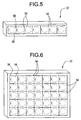
- digital X-ray detectors generally have an array of cells 54, each cell 54 including a layer of X-ray sensitive material 56 such as phosphor and an electronic means 58, such as a photodiode and transistor, located beneath the X-ray sensitive material 56 for producing an output signal that is indicative of the X-rays impinging on the X-ray sensitive material.
- the radiation detector 32 can be configured as either a linear array ( Figure 5) or an area array ( Figure 6).
- the array would preferably, but not necessarily, have a width of at least eight inches (approximately 20cm), although this could vary depending on the particular fuselage structure of interest.
- a linear array would permit a continuous scan of the fuselage 12 at each scanning station. That is, at each scanning station, the detector positioning system 34 would continuously move the radiation detector 32 over the fuselage 12, and successive lines of data would be transmitted to the controller 36. The controller 36 would then build the image one line at a time. This avoids repeated mechanical starting and stopping of the detector positioning system 34.
- one or more of the radiation detectors 32 are mounted on the curved guide rails 48 of a selected scanning station.
- the source positioning system 30 is activated to move the radiation source 28 into longitudinal alignment with the selected scanning station.
- the radiation source 28 is then turned on so that the adjacent region of the fuselage 12 above the passenger deck 20 is illuminated with radiation.
- the detector positioning system 34 is activated to cause the radiation detector or detectors 34 to travel over the outer surface of the fuselage 12. If one radiation detector is employed, then it travels the over the entire distance of the guide rails 48, up one side of the fuselage 12, over the crown and down the other side. If two radiation detectors 32 are employed at the scanning station, then each one travels up an opposing side of the fuselage 12, meeting at the crown.
- Radiation emitted by the radiation source 28 passes through the fuselage 12 and impinges on each radiation detector 32.
- the radiation is converted into electrical signals that are fed to the controller 36.
- the controller 36 processes these signals and generates images that are displayed on the monitor 40. An operator inspects the images for defects.
- the radiation detectors 32 are moved to the next scanning station, and the source positioning system 30 again moves the radiation source 28 into longitudinal alignment.
- the inspection at this scanning station is then carried out in the same manner with the radiation detectors 32 being moved over the outer surface of the fuselage while the radiation source 28 is turned on. This process is repeated for each scanning station until the entire fuselage 12 has been inspected.
- radiation detectors 32 can be simultaneously employed at multiple scanning stations to decrease the overall time needed to inspect the entire fuselage 12. This approach would require an equal number of radiation sources 28 located in the fuselage 12.
- One preferred embodiment would be to start inspections at opposite ends of the fuselage 12 and move toward the center.
- the radiation source 28 is located inside of the fuselage 12 and the radiation detector or detectors 32 are located outside of the fuselage 12.
- This arrangement is generally best for image resolution because the radiation detectors 32 can be located fairly close to the fuselage structure being inspected, thereby minimizing the magnification effect. Excessive magnification of the images can result in degradation of image resolution. On the other hand, some magnification would be helpful in inspecting the images and is thus desirable.
- Some commercially available X-ray tubes have built-in magnification capability.
- the system 10 could also include a separate magnification element located between the radiation source 28 and the radiation detector 32.
- the system 10 can be alternatively configured so that the radiation source 28 is located outside and the radiation detectors 32 are located inside of the fuselage 12. Locating the radiation detectors inside of the fuselage 12 will generally place them farther away from the fuselage structure being inspected. A microfocus tube could be used to compensate for excessive magnification that may result from this arrangement.
- the alternative detector positioning system 134 utilizes a rail trolley system that has remote longitudinal positioning capability to move to successive scanning stations in coordination with the radiation source.
- the system 134 includes two curved guide rails 148 mounted on wheels 160 over the crown of the fuselage 12.
- the guide rails 148 are oriented circumferentially with respect to the fuselage 12 and are spaced apart longitudinally.
- the detector positioning system 134 further includes a second carrier 150 and a support beam 152 that supports the second carrier 150.
- the support beam 152 is slidingly mounted between the guide rails 148.
- the radiation detector 32 is mounted to the underside of the second carrier 150 so as to face the fuselage 12.
- the support beam 152 is moved along the guide rails 148 under the control of the controller 36 by any conventional motive means in a manner known in the art. This moves the radiation detector 32 circumferentially over the outer surface of the fuselage 12.
- the second carrier 150 (and thus the radiation detector 32) has a local lateral or longitudinal motion capability relative to the support beam 152. This lateral motion enhances the view of the frame member 14 (or whichever fuselage structure is being inspected) during an inspection.
- a motive means such as an electric motor (not shown) is provided to drive the wheels 160 under the control of the controller 136 in a manner known in the art to thereby move the curved guide rails 148 longitudinally along the fuselage 12.
- the radiation detector 32 can be positioned at the selected scanning station as the radiation source is positioned inside the cabin. Exact longitudinal alignment of the radiation detector 32 with the radiation source 28 is not required because the width of the radiation beam emitted by the radiation source will generally cover both sides of the frame member 14. Furthermore, the radiation detector position can be adjusted by moving the second carrier 150 relative to the support beam 152 prior to the circumferential scan.
- the foregoing has described a radiographic inspection system 10 that provides high speed digital inspection of aircraft fuselages.
- the system 10 allows for inspection without removal of interior bins, panels, insulation, lights and wiring, thereby realizing substantial time and cost savings over traditional inspection practices.
- the system 10 can also stage other nondestructive testing (NDT) sensors so that other NDT modalities can be performed simultaneously with the radiographic inspection, thereby further enhancing productivity.
- NDT nondestructive testing
- an ultrasonic probe could be mounted onto one of the positioning systems to inspect along the longitudinal direction at lap joints and stringers for corrosion and cracking of fasteners.
Landscapes
- Physics & Mathematics (AREA)
- Health & Medical Sciences (AREA)
- Life Sciences & Earth Sciences (AREA)
- Chemical & Material Sciences (AREA)
- Analytical Chemistry (AREA)
- Biochemistry (AREA)
- General Health & Medical Sciences (AREA)
- General Physics & Mathematics (AREA)
- Immunology (AREA)
- Pathology (AREA)
- Analysing Materials By The Use Of Radiation (AREA)
Applications Claiming Priority (4)
| Application Number | Priority Date | Filing Date | Title |
|---|---|---|---|
| US17508900P | 2000-01-07 | 2000-01-07 | |
| US175089P | 2000-01-07 | ||
| US09/643,688 US6466643B1 (en) | 2000-01-07 | 2000-08-22 | High speed digital radiographic inspection of aircraft fuselages |
| US643688 | 2003-08-19 |
Publications (3)
| Publication Number | Publication Date |
|---|---|
| EP1130385A2 EP1130385A2 (en) | 2001-09-05 |
| EP1130385A3 EP1130385A3 (en) | 2003-01-15 |
| EP1130385B1 true EP1130385B1 (en) | 2007-07-25 |
Family
ID=26870850
Family Applications (1)
| Application Number | Title | Priority Date | Filing Date |
|---|---|---|---|
| EP01300075A Expired - Lifetime EP1130385B1 (en) | 2000-01-07 | 2001-01-05 | High speed digital radiographic inspection of aircraft fuselages |
Country Status (7)
| Country | Link |
|---|---|
| US (1) | US6466643B1 (enExample) |
| EP (1) | EP1130385B1 (enExample) |
| JP (1) | JP4719900B2 (enExample) |
| BR (1) | BR0100024B1 (enExample) |
| DE (1) | DE60129494T2 (enExample) |
| SG (1) | SG105479A1 (enExample) |
| TR (1) | TR200003697A2 (enExample) |
Families Citing this family (34)
| Publication number | Priority date | Publication date | Assignee | Title |
|---|---|---|---|---|
| US6633384B1 (en) * | 1998-06-30 | 2003-10-14 | Lockheed Martin Corporation | Method and apparatus for ultrasonic laser testing |
| US7561281B2 (en) * | 1998-06-30 | 2009-07-14 | Lockheed Martin Corporation | System and method for controlling tube thickness |
| US6657733B1 (en) * | 1998-06-30 | 2003-12-02 | Lockheed Martin Corporation | Method and apparatus for detecting ultrasonic surface displacements using post-collection optical amplification |
| US7612890B2 (en) * | 1998-06-30 | 2009-11-03 | Lockheed Martin Corporation | System and method for controlling wafer temperature |
| US7545509B2 (en) * | 1998-06-30 | 2009-06-09 | Lockheed Martin Corporation | System and method for online control of paper elasticity and thickness |
| US7342665B2 (en) * | 1998-06-30 | 2008-03-11 | Drake Jr Thomas E | System and method for control of paint thickness |
| US7286241B2 (en) * | 1999-06-24 | 2007-10-23 | Lockheed Martin Corporation | System and method for high-speed laser detection of ultrasound |
| CA2411632C (en) * | 2000-07-14 | 2013-09-17 | Lockheed Martin Corporation | System and method for locating and positioning an ultrasonic signal generator for testing purposes |
| PL349169A1 (en) * | 2000-09-12 | 2002-03-25 | Gen Electric | Method of and apparatus for radiographically inspecting the fuselages of aircrafts |
| US6614872B2 (en) * | 2001-01-26 | 2003-09-02 | General Electric Company | Method and apparatus for localized digital radiographic inspection |
| US6618465B2 (en) * | 2001-11-12 | 2003-09-09 | General Electric Company | X-ray shielding system and shielded digital radiographic inspection system and method |
| FR2836994B1 (fr) | 2002-03-05 | 2004-12-17 | Airbus France | Procede et dispositif de controle de pieces par rayons x |
| US6662088B1 (en) * | 2002-06-28 | 2003-12-09 | General Electric Company | Methods and systems for inspecting aircraft fuselage frames |
| US7272254B2 (en) * | 2003-07-09 | 2007-09-18 | General Electric Company | System and method for analyzing and identifying flaws in a manufactured part |
| US6925145B2 (en) * | 2003-08-22 | 2005-08-02 | General Electric Company | High speed digital radiographic inspection of piping |
| EP1660851B1 (en) * | 2003-08-27 | 2017-10-25 | Airbus Operations Limited | Optically measuring the displacement or load for an aircraft component, landing gear, braking control |
| US7506549B2 (en) * | 2003-08-27 | 2009-03-24 | Airbus Uk Limited | Method and apparatus suitable for measuring the displacement or load on an aircraft component |
| US7218706B2 (en) * | 2004-12-20 | 2007-05-15 | General Electric Company | Energy discrimination radiography systems and methods for inspecting industrial components |
| US7266174B2 (en) * | 2005-03-07 | 2007-09-04 | General Electric Company | Radiographic inspection of airframes and other large objects |
| US7341376B2 (en) * | 2006-03-23 | 2008-03-11 | General Electric Company | Method for aligning radiographic inspection system |
| US7463714B2 (en) * | 2006-10-17 | 2008-12-09 | The Boeing Company | Foreign object detection |
| GB0915141D0 (en) * | 2009-08-28 | 2009-10-07 | Shawcor Ltd | Method and apparatus for external pipeline weld inspection |
| US8693613B2 (en) * | 2010-01-14 | 2014-04-08 | General Electric Company | Nuclear fuel pellet inspection |
| US8503610B1 (en) | 2010-11-23 | 2013-08-06 | The Boeing Company | X-ray inspection tool |
| US8396187B2 (en) * | 2010-12-10 | 2013-03-12 | The Boeing Company | X-ray inspection tool |
| US8542876B1 (en) | 2011-03-28 | 2013-09-24 | The Boeing Company | Methods and systems for enhancing backscatter X-ray foreign object debris detection |
| US8588262B1 (en) | 2011-09-07 | 2013-11-19 | The Boeing Company | Quantum dot detection |
| JP6031339B2 (ja) | 2012-11-21 | 2016-11-24 | 富士フイルム株式会社 | 透視画像濃度補正方法、非破壊検査方法、及び画像処理装置 |
| EP2827095A1 (en) * | 2013-07-18 | 2015-01-21 | BAE Systems PLC | Material inspection device |
| CA2918435A1 (en) * | 2013-07-18 | 2015-01-22 | Bae Systems Plc | Material inspection device |
| GB2519955B (en) * | 2013-11-01 | 2015-09-30 | Paragon Inspection Ltd | Apparatus and method for radiological pipe inspection |
| US10168288B2 (en) * | 2015-09-21 | 2019-01-01 | General Electric Company | System for radiography imaging and method of operating such system |
| CN113614521B (zh) * | 2019-03-29 | 2024-10-15 | 富士胶片株式会社 | 图像处理装置、放射线图像摄影系统、图像处理方法及记录介质 |
| CN110282152A (zh) * | 2019-06-28 | 2019-09-27 | 烟台海蝶玩具有限公司 | 一种小型飞机辅助维修系统 |
Family Cites Families (10)
| Publication number | Priority date | Publication date | Assignee | Title |
|---|---|---|---|---|
| US3835324A (en) * | 1972-10-04 | 1974-09-10 | O Weigle | Pipe weld inspection method and apparatus |
| US3911733A (en) * | 1974-04-01 | 1975-10-14 | Trw Inc | Optical signature method and apparatus for structural integrity verification |
| US4078180A (en) * | 1976-03-17 | 1978-03-07 | United States Steel Corporation | X-ray inspection of welds |
| CA1206278A (en) * | 1981-10-16 | 1986-06-17 | David R. Stamp | Fluoroscopic examination of pipe girth welds |
| US5083451A (en) | 1989-08-21 | 1992-01-28 | J. V. - 1, Ltd. | Method and apparatus for monitoring aircraft fuselage deterioration |
| US5014293A (en) * | 1989-10-04 | 1991-05-07 | Imatron, Inc. | Computerized tomographic x-ray scanner system and gantry assembly |
| US4976136A (en) | 1989-10-13 | 1990-12-11 | Willan W Craig | Method of testing for fuselage cracks |
| US5237598A (en) | 1992-04-24 | 1993-08-17 | Albert Richard D | Multiple image scanning X-ray method and apparatus |
| JP2774446B2 (ja) * | 1994-06-14 | 1998-07-09 | 石川島検査計測株式会社 | 配管検査用放射線照射装置 |
| JP3730040B2 (ja) * | 1998-12-14 | 2005-12-21 | Jfe工建株式会社 | X線検査装置及びx線検査方法 |
-
2000
- 2000-08-22 US US09/643,688 patent/US6466643B1/en not_active Expired - Fee Related
- 2000-12-13 TR TR2000/03697A patent/TR200003697A2/xx unknown
- 2000-12-30 SG SG200007712A patent/SG105479A1/en unknown
-
2001
- 2001-01-05 BR BRPI0100024-1A patent/BR0100024B1/pt not_active IP Right Cessation
- 2001-01-05 JP JP2001000294A patent/JP4719900B2/ja not_active Expired - Fee Related
- 2001-01-05 EP EP01300075A patent/EP1130385B1/en not_active Expired - Lifetime
- 2001-01-05 DE DE60129494T patent/DE60129494T2/de not_active Expired - Lifetime
Also Published As
| Publication number | Publication date |
|---|---|
| BR0100024A (pt) | 2001-10-30 |
| TR200003697A2 (tr) | 2001-08-21 |
| DE60129494T2 (de) | 2008-04-17 |
| JP4719900B2 (ja) | 2011-07-06 |
| EP1130385A3 (en) | 2003-01-15 |
| JP2001264271A (ja) | 2001-09-26 |
| BR0100024B1 (pt) | 2013-02-19 |
| SG105479A1 (en) | 2004-08-27 |
| EP1130385A2 (en) | 2001-09-05 |
| DE60129494D1 (de) | 2007-09-06 |
| US6466643B1 (en) | 2002-10-15 |
Similar Documents
| Publication | Publication Date | Title |
|---|---|---|
| EP1130385B1 (en) | High speed digital radiographic inspection of aircraft fuselages | |
| US6507635B2 (en) | Method and apparatus for radiographic inspection of aircraft fuselages | |
| US6614872B2 (en) | Method and apparatus for localized digital radiographic inspection | |
| US6618465B2 (en) | X-ray shielding system and shielded digital radiographic inspection system and method | |
| US7722251B2 (en) | Device for inspecting contraband in aviation cargo container | |
| US7702070B2 (en) | Device and method for inspecting contraband in aviation cargo container | |
| US5585564A (en) | Ultrasonic inspection system for laminated stiffeners | |
| US7266174B2 (en) | Radiographic inspection of airframes and other large objects | |
| EP1193491A2 (en) | Radiographic system and method for inspecting aircraft fuselages | |
| WO2025140519A1 (zh) | 货物检查设备及其检查方法 | |
| EP1939610A1 (en) | System and method for radiographic inspection without a-priori information of inspected object | |
| Shedlock et al. | X‐RAY BACKSCATTER IMAGING FOR AEROSPACE APPLICATIONS | |
| JPH09292351A (ja) | 放射線検査装置 | |
| JPS60256034A (ja) | 産業用ctスキヤナ | |
| US20240310306A1 (en) | X-ray line scan for foreign object debris detection | |
| Orphan et al. | Mobile neutron radiography system for aircraft inspection | |
| Shields et al. | Aircraft inspection using neutron radioscopic techniques | |
| GB2619960A (en) | X-ray imaging apparatus | |
| KR20180037344A (ko) | 전산단층촬영장치 및 방법 | |
| Hocking et al. | X-rays used to measure defect depths |
Legal Events
| Date | Code | Title | Description |
|---|---|---|---|
| PUAI | Public reference made under article 153(3) epc to a published international application that has entered the european phase |
Free format text: ORIGINAL CODE: 0009012 |
|
| AK | Designated contracting states |
Kind code of ref document: A2 Designated state(s): AT BE CH CY DE DK ES FI FR GB GR IE IT LI LU MC NL PT SE TR |
|
| AX | Request for extension of the european patent |
Free format text: AL;LT;LV;MK;RO;SI |
|
| PUAL | Search report despatched |
Free format text: ORIGINAL CODE: 0009013 |
|
| AK | Designated contracting states |
Kind code of ref document: A3 Designated state(s): AT BE CH CY DE DK ES FI FR GB GR IE IT LI LU MC NL PT SE TR |
|
| AX | Request for extension of the european patent |
Free format text: AL;LT;LV;MK;RO;SI |
|
| 17P | Request for examination filed |
Effective date: 20030715 |
|
| AKX | Designation fees paid |
Designated state(s): DE FR GB |
|
| GRAP | Despatch of communication of intention to grant a patent |
Free format text: ORIGINAL CODE: EPIDOSNIGR1 |
|
| GRAS | Grant fee paid |
Free format text: ORIGINAL CODE: EPIDOSNIGR3 |
|
| GRAA | (expected) grant |
Free format text: ORIGINAL CODE: 0009210 |
|
| AK | Designated contracting states |
Kind code of ref document: B1 Designated state(s): DE FR GB |
|
| REG | Reference to a national code |
Ref country code: GB Ref legal event code: FG4D |
|
| REF | Corresponds to: |
Ref document number: 60129494 Country of ref document: DE Date of ref document: 20070906 Kind code of ref document: P |
|
| ET | Fr: translation filed | ||
| PLBE | No opposition filed within time limit |
Free format text: ORIGINAL CODE: 0009261 |
|
| STAA | Information on the status of an ep patent application or granted ep patent |
Free format text: STATUS: NO OPPOSITION FILED WITHIN TIME LIMIT |
|
| 26N | No opposition filed |
Effective date: 20080428 |
|
| PGFP | Annual fee paid to national office [announced via postgrant information from national office to epo] |
Ref country code: FR Payment date: 20130211 Year of fee payment: 13 Ref country code: GB Payment date: 20130125 Year of fee payment: 13 Ref country code: DE Payment date: 20130129 Year of fee payment: 13 |
|
| REG | Reference to a national code |
Ref country code: DE Ref legal event code: R119 Ref document number: 60129494 Country of ref document: DE |
|
| GBPC | Gb: european patent ceased through non-payment of renewal fee |
Effective date: 20140105 |
|
| REG | Reference to a national code |
Ref country code: DE Ref legal event code: R119 Ref document number: 60129494 Country of ref document: DE Effective date: 20140801 |
|
| PG25 | Lapsed in a contracting state [announced via postgrant information from national office to epo] |
Ref country code: DE Free format text: LAPSE BECAUSE OF NON-PAYMENT OF DUE FEES Effective date: 20140801 |
|
| REG | Reference to a national code |
Ref country code: FR Ref legal event code: ST Effective date: 20140930 |
|
| PG25 | Lapsed in a contracting state [announced via postgrant information from national office to epo] |
Ref country code: GB Free format text: LAPSE BECAUSE OF NON-PAYMENT OF DUE FEES Effective date: 20140105 Ref country code: FR Free format text: LAPSE BECAUSE OF NON-PAYMENT OF DUE FEES Effective date: 20140131 |