EP1130375A1 - Messsystem zur Ermittlung von Luftdaten eines Luftfahrzeugs sowie ein Verfahren zur Bestimmung der Luftdaten - Google Patents
Messsystem zur Ermittlung von Luftdaten eines Luftfahrzeugs sowie ein Verfahren zur Bestimmung der Luftdaten Download PDFInfo
- Publication number
- EP1130375A1 EP1130375A1 EP01100110A EP01100110A EP1130375A1 EP 1130375 A1 EP1130375 A1 EP 1130375A1 EP 01100110 A EP01100110 A EP 01100110A EP 01100110 A EP01100110 A EP 01100110A EP 1130375 A1 EP1130375 A1 EP 1130375A1
- Authority
- EP
- European Patent Office
- Prior art keywords
- air data
- measuring
- determining
- aircraft
- fuselage segment
- Prior art date
- Legal status (The legal status is an assumption and is not a legal conclusion. Google has not performed a legal analysis and makes no representation as to the accuracy of the status listed.)
- Granted
Links
- 238000000034 method Methods 0.000 title claims description 17
- 238000011088 calibration curve Methods 0.000 claims abstract description 22
- 230000001133 acceleration Effects 0.000 claims abstract description 11
- 238000011156 evaluation Methods 0.000 claims abstract 5
- 238000005259 measurement Methods 0.000 claims description 35
- 238000000926 separation method Methods 0.000 claims 2
- 230000036962 time dependent Effects 0.000 claims 1
- 238000009826 distribution Methods 0.000 description 11
- 230000008859 change Effects 0.000 description 8
- 125000006850 spacer group Chemical group 0.000 description 7
- 239000000523 sample Substances 0.000 description 6
- 230000003068 static effect Effects 0.000 description 5
- 230000008901 benefit Effects 0.000 description 3
- 230000000694 effects Effects 0.000 description 3
- 238000000691 measurement method Methods 0.000 description 3
- 238000000418 atomic force spectrum Methods 0.000 description 2
- 238000009530 blood pressure measurement Methods 0.000 description 2
- 238000005516 engineering process Methods 0.000 description 2
- 230000003287 optical effect Effects 0.000 description 2
- 239000010409 thin film Substances 0.000 description 2
- RZVHIXYEVGDQDX-UHFFFAOYSA-N 9,10-anthraquinone Chemical compound C1=CC=C2C(=O)C3=CC=CC=C3C(=O)C2=C1 RZVHIXYEVGDQDX-UHFFFAOYSA-N 0.000 description 1
- 239000000443 aerosol Substances 0.000 description 1
- 230000009286 beneficial effect Effects 0.000 description 1
- 230000005540 biological transmission Effects 0.000 description 1
- 230000008878 coupling Effects 0.000 description 1
- 238000010168 coupling process Methods 0.000 description 1
- 238000005859 coupling reaction Methods 0.000 description 1
- 239000013078 crystal Substances 0.000 description 1
- 238000005520 cutting process Methods 0.000 description 1
- 230000001419 dependent effect Effects 0.000 description 1
- 238000009795 derivation Methods 0.000 description 1
- 238000001514 detection method Methods 0.000 description 1
- 238000006073 displacement reaction Methods 0.000 description 1
- 230000007613 environmental effect Effects 0.000 description 1
- 230000001771 impaired effect Effects 0.000 description 1
- 230000002452 interceptive effect Effects 0.000 description 1
- 238000004519 manufacturing process Methods 0.000 description 1
- 239000000463 material Substances 0.000 description 1
- 229910021421 monocrystalline silicon Inorganic materials 0.000 description 1
- 230000002093 peripheral effect Effects 0.000 description 1
- 238000007781 pre-processing Methods 0.000 description 1
- 230000008569 process Effects 0.000 description 1
Images



Classifications
-
- G—PHYSICS
- G01—MEASURING; TESTING
- G01P—MEASURING LINEAR OR ANGULAR SPEED, ACCELERATION, DECELERATION, OR SHOCK; INDICATING PRESENCE, ABSENCE, OR DIRECTION, OF MOVEMENT
- G01P13/00—Indicating or recording presence, absence, or direction, of movement
- G01P13/02—Indicating direction only, e.g. by weather vane
- G01P13/025—Indicating direction only, e.g. by weather vane indicating air data, i.e. flight variables of an aircraft, e.g. angle of attack, side slip, shear, yaw
-
- G—PHYSICS
- G01—MEASURING; TESTING
- G01M—TESTING STATIC OR DYNAMIC BALANCE OF MACHINES OR STRUCTURES; TESTING OF STRUCTURES OR APPARATUS, NOT OTHERWISE PROVIDED FOR
- G01M9/00—Aerodynamic testing; Arrangements in or on wind tunnels
- G01M9/06—Measuring arrangements specially adapted for aerodynamic testing
- G01M9/062—Wind tunnel balances; Holding devices combined with measuring arrangements
Definitions
- the invention relates to a measuring system for determining air data of an aircraft and a method for determining the air data, the aircraft being for example can be a manned or unmanned aircraft, or a missile.
- Conventional air data systems preferably determine the current and local ones Aircraft flow angle as well as current and local static and dynamic pressures or only some of these sizes. These local sizes become So-called undisturbed variables are determined in the usual way, i.e. Angle of attack, sliding angle and pressures that currently exist in the flow undisturbed by the aircraft. These undisturbed variables are used to determine the attitude and speed as well as other flight-specific sizes of the aircraft.
- Such conventional Air data systems are usually based on the measurement of pressures. Doing so the contour uses outstanding Pitot pressure probes. There is still Measuring devices that measure the pressure distributions of the surface of the fuselage nose.
- Another disadvantage is that in many aircraft there is an active on - board radar in the front part of the Fuselage nose segment is present, so that such probes are not in this area can be provided without interfering with the function of the on-board radar.
- On Attachment of the measuring probes in the area behind the front fuselage segment required however, a very large calibration and correction effort for use in operation.
- the measurement of the pressure distribution at the top of the fuselage or at other of the flow facing parts of the aircraft can also be integrated into the surface Pressure sensors are made.
- the solution offers the advantage that the Total resistance of the aircraft is not increased.
- Another advantage is that the military detectability of the aircraft by protruding from the aircraft contour Measuring probes is not significantly affected due to the low radar signature. This kind However, the measuring probes run the risk that the measurements, e.g. due to ice build-up, dirt or bird strike can be changed effectively. This will make the pressure measurements significantly impaired or even impossible, leading to a total failure at least individual sensors and even the air data system.
- the measuring device has none from the fuselage surface of the Aircraft's outstanding components, does not require any pressure holes Pressure measurement on the surface and is resistant to the effects of objects or foreign bodies and unfavorable environmental conditions.
- the arrangement of the Measuring device according to the invention in the area behind the front fuselage segment the on-board radar does not affect the measurement accuracy, so that no increase in System effort for measurement data correction is required.
- FIG. 1 shows a front fuselage segment or fuselage nose segment when viewed in the direction of flight 1 and a rear fuselage segment 2, which form the front part of an aircraft fuselage.
- the measuring device 10 detects one equivalent load profile in at least one measuring section with an extension in Circumferential direction, the measuring section also each having an areal extension may have.
- the measuring device 10 is a Force measuring device 11.
- the course of the load is then - among other things taking into account the inertial forces acting on the front fuselage segment 1 act against the rear fuselage segment 2, - by Comparison with at least one calibration curve, the set of air data sought is derived.
- On Set of air data preferably has the angle of attack, the shift angle, the static and dynamic pressure and the Mach number derived from it.
- the front fuselage segment 1 has a tip 3 and can, for example, the radome of an aircraft in which a radar device (not shown) is mounted. In this case often prescribed that no further measuring device or device, and in particular no air data sensors may be attached to the front fuselage segment 1, as this would interfere with the operation of a radar.
- the rear fuselage segment is 2 preferably from the front, i.e. seen from the top 3 in front of the cockpit appropriate.
- the front fuselage segment 1 and the rear fuselage segment 2 can in a first, in The embodiment of the invention shown in Figure 1 for performing the Stress measurement should be physically separate components of the fuselage According to the invention, those occurring between the front 1 and rear 2 fuselage segments Forces are used to determine the equivalent load curve.
- a alternative second embodiment not shown in the figures, can be the front 1 together with the rear 2 fuselage segment can also be designed uniformly, the Determination of the equivalent load curve then by determining the strain or voltage curve in the at least one measuring section between the front 1 and rear 2 fuselage segment.
- spacer elements 12 can also be between the fuselage segments 1, 2 be arranged.
- the spacers 12 provided are intended to be the ones that occur Limit deformations due to external air loads and inertial forces to To prevent overloading of the measuring device 11.
- additional guide elements may be provided around the front Fuselage segment 1 relative to the rear fuselage segment 2, in particular in the radial direction align.
- Fig. 2 the section A-A through the measuring device 10 or force measuring device 11 with Viewing direction shown from the front, so that the force measuring device 10 in its cross section 13 and the arrangement of the spacer elements 12 in relation to the measuring device 10 is shown.
- the force measuring device 11 detects the load profile over the Measuring section, i.e. in the embodiment of Figures 1 and 2 over the entire Hull circumference.
- the load curve represents a force curve.
- the cross section 13, in which the force profile is measured preferably runs within the outer contour of the fuselage at this point.
- the spacers 12 are preferably radially inside and outside the cross section 13 of the force measuring device 11 arranged. Alternatively, however, only one spacer could be radial be arranged inside or outside the cross section 13.
- the spacers 12 do not have to run continuously in the circumferential direction, but can also selected points inside or outside along the circumference of the cross section 13 to be appropriate.
- the spacer elements 12 can, however, also in a different way than in the 1 or 2 can be designed according to the prior art.
- the at least one accelerometer 14 is used to record, for example, due to dynamic flight maneuvers or Structural couplings acting on the front fuselage segment 1 inertial forces. This can also by measuring the acceleration at a suitable point in the rear Fuselage segment 2 happen when appropriate assumptions about the weight and the Structure of the front fuselage segment 1 and a suitable estimation method for Derivation of the inertial forces on the front fuselage segment 1 can be used.
- the Inertia measurement is required because the aerodynamic measurement device 10 Loads plus the inertial forces are measured, however for the determination of the Air data only require the aerodynamic loads.
- a three-axis accelerometer 14 in the front fuselage segment 1 provided that spaced from the axis of symmetry 15 of the fuselage segment 1 is arranged.
- you can also use it to improve the measurement further accelerometers 14 may be provided.
- a plurality of acceleration sensors 14 are in the Area of the peripheral surface of the fuselage segment 1 arranged.
- a single or additional accelerometer 14 relatively close to the tip 3 has the advantage that with pitching vibrations, the maximum acceleration in the fuselage nose segment 1 is detected.
- the purpose of the measuring device 10 integrated in the fuselage cross section 13 is Determination of the force distribution along the circumference. This can also be done, for example by using strain gauges (strain gauges), which can be achieved in a known manner over the scope or over at least a section in the area between the front 1 and rear 2 fuselage segment are arranged. In this case, the front one Fuselage segment 1 executed uniformly with the rear fuselage segment 2. That included underlying measurement principle is the change in resistance of a wire as a result of Material expansion. This stretch and the associated change in resistance leaves assign a corresponding force via a calibration. To increase the The strain gauges can be used for accuracy and temperature compensation in a so-called Full bridge (Wheatston bridge) must be connected together.
- Straatston bridge Full bridge
- Every single Force measuring point in the measuring cross section thus corresponds to a full bridge strain gauge.
- the Redundancy of the measuring system can be increased with an increasing number of measuring points, i.e. Force measuring points, increase, since it can be assumed that the curve of the force in the measuring cross-section even with the failure of individual measuring points with sufficient Can clearly determine accuracy.
- Another way of measuring force is to use pressure sensors, the knowledge of the area on which the pressure acts, also the determination of the allow the front fuselage segment 1 acting total loads.
- Piezoresitive pressure sensors are used, whereby in In this case, the front fuselage segment 1 is designed as a separate component.
- this measurement principle based on piezoresitive pressure sensors is based on the piezoresistive Effect, i.e. the change in the electrical resistance of crystals under the influence a mechanical tension. It can be calibrated Resistance change with knowledge of the sensor size the corresponding pressure load and thus also assign the corresponding force.
- the technical realization of this Monocrystalline silicon sensors enable the production of Pressure sensors of the smallest dimensions in the so-called Thin film technology.
- the front fuselage segment also in this case 1 is designed as a separate component.
- the underlying measuring principle is based on the Displacement of an interference pattern due to a change in length of the observed Object. This shift in the interference pattern can be calibrated Length change can be assigned. This can be done in a further calibration Assign a change in length to a mechanical tension or a force.
- the metrological implementation of the measuring methods described takes place according to the state of the technique.
- the Air flow exerted on the front fuselage segment 1 force in the form of a resultant flow vector 20 represent. Physically this results from this Flow vector 20 a force application point 21 on the measuring device 10 or on Cross section 13 of the force measuring device 10, which is generally axially spaced from Fuselage longitudinal axis is located. This results in a certain one about each Measuring section of the measuring device 10 in the circumferential direction distribution of a equivalent load depending on the angle of attack, the sliding angle, the static and dynamic pressure and the Mach number derived from it.
- Such a load distribution over the circumference of the measuring section can be a force or stress or strain measurement, depending on the measuring method or measuring devices 10 used.
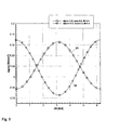
- a load distribution for selected parameter values is shown as an example for an assumed aircraft type in FIGS. 3, 4 and 5 in order to clarify the suitability of the measurement method with regard to the uniqueness of the assignment of the measured load distribution curves to specific flight conditions.
- the representation is based on a force measurement with a device according to FIGS. 1 and 2. 3 to 5, the circumferential angle ⁇ (phi) is plotted on the abscissa 31.
- a mechanical stress occurring over the circumference of the measuring cross-section 13 is plotted on the ordinate 32 in the axial direction, which results from the flow vector 20 at the corresponding point denoted by the angle ⁇ in a corresponding measuring device 10 in cross-section 13.
- the stress is plotted over the measurement cross section in the unit N / mm 2 .
- the dimensions of the angle ⁇ from 0 to 2 ⁇ are plotted along the abscissa 31.
- the curve 33 represents the Voltage across the measurement cross section at an angle of attack of the aircraft equal to zero and represents a sliding angle equal to zero.
- the angle of attack of the aircraft corresponds to generally not the angle of attack of the front fuselage segment 1, since the Inflow angle of the front fuselage segment 1 is the direction of the free inflow in Reference to the line of symmetry of the fuselage segment 1 is.
- 4 An example is the line of symmetry of the front fuselage segment 1 with respect to the longitudinal axis of the aircraft tilted down 5.5 degrees. Therefore, in this example, it also results in an aircraft angle of attack of 0 degrees, a voltage component over the measurement cross section 13, which is not constant over the circumference.
- curve 34 is the voltage curve along the circumference of the measuring cross-section at a positive angle of attack of 10 degrees and a sliding angle equal to zero. Curves 33 and 34 apply for a Mach number of 0.4.
- the voltage curve 35 is also shown at an angle of attack of Airplane is zero and a sliding angle is zero.
- Second shows 4 shows a curve 36 with the voltage curve at an angle of attack equal to zero and a sliding angle of 4 degrees. Curves 35 and 36 apply to a Mach number of 0.4.
- FIG. 5 shows a curve 37 which shows the voltage curve along the circumference of the Measuring cross-section with a positive angle of attack of 10 degrees and a sliding angle represents zero with a Mach number equal to 0.4.
- the curve 37 corresponds to the curve 34 of the Figure 3 on a different scale.
- the curve 38 in FIG. 5 shows the voltage curve for an angle of attack of 10 degrees, a shift angle of 0 degrees and a Mach number of 0.8.
- the voltage profiles or load profiles occurring in the measurement cross section 13 and shown by way of example in FIGS. 3, 4 and 5 do not yet allow a direct and unambiguous determination of the measured variables sought, that is to say in particular the angle of attack ⁇ , slide angle ⁇ and speed v ⁇ or dynamic pressure q ⁇ , since the profile the measurement curve depends on these three measured variables sought and additionally on the acceleration forces acting on the front fuselage segment 1.
- the speed v ⁇ , the dynamic pressure q ⁇ , and the Mach number M are to be assumed as equivalent values, whereby the static temperature and the static air pressure, which defines the so-called pressure height, must be taken into account when converting according to known formulas.
- the forces measured in the measurement cross section 13 are to be separated from the inertial forces measured by means of accelerometers, which act on the front fuselage segment 1, in order to determine those forces which act on the fuselage segment 1 due to the aerodynamic load .
- accelerometers which act on the front fuselage segment 1
- all combinations of ⁇ , ⁇ , v ⁇ or q ⁇ that can occur for any flight condition within the flight envelope and the resulting voltage profiles in the measurement cross section 13 are to be determined and stored in a database.
- the load distribution which arises during the flight in the measuring section becomes permanently compared with the calibration curves stored in the database.
- the one Calibration curve that is most similar to the load curve measured in flight has, is used to assign the desired measured variables to the current one Flight state used.
- Determining the calibration curve which is the most similar to that in flight measured curve and adjusted for the inertial forces is, for example, after using the least squares method.
- the determination of the associated calibration curve, which correctly describes the flight state can be further optimized by using a calibration curve that is in agreement with a curve measured in flight at the measurement time t 1 as a starting solution when searching for the calibration curve in the subsequent measurement time t 2 is used.
- the values which describe the flight state at the measurement time t 2 are used again as starting values in the search for a solution for the measurement time t 3 .
- the possibilities to be considered can be narrowed further by using the equations of motion valid for the missile.
- the measuring device 10 delivers signals, which the current angle of attack, the momentary sliding angle and the current Dynamic pressure, for example, passed to a signal preprocessing and from there forward via analog or digital lines to an air data system, which in turn includes a flight control system with actuators and control devices in the cockpit and coupled with other systems or system functions.
- both mechanical components of the Measuring device 10 and its electrical components can be provided several times.
- measuring devices can also be used to the course of an equivalent load over the respectively intended measuring section to capture.
- a combination of different types of measuring devices can also be used be provided.
Landscapes
- Physics & Mathematics (AREA)
- General Physics & Mathematics (AREA)
- Engineering & Computer Science (AREA)
- Aviation & Aerospace Engineering (AREA)
- Fluid Mechanics (AREA)
- Measuring Fluid Pressure (AREA)
- Investigating Or Analysing Materials By Optical Means (AREA)
- Arrangements For Transmission Of Measured Signals (AREA)
- Measuring Volume Flow (AREA)
Abstract
Description
- Fig. 1 einen Längsschnitt durch den vorderen Teil des Rumpfs eines Luftfahrzeugs mit der erfindungsgemäßen Meßvorrichtung,
- Fig. 2 einen Querschnitt entlang der Linie A-A der Fig. 1,
- Fig. 3 eine Darstellung der Spannungs-Verteilung über den Umfang des Meßquerschnitts in Abhängigkeit des Anstellwinkels alpha, des Schiebewinkels beta und der Machzahl M bei zwei verschiedenen Anstellwinkeln alpha und unveränderter Machzahl M und unverändertem Schiebewinkel beta,
- Fig. 4 eine Darstellung der Spannungs-Verteilung über den Umfang des Meßquerschnitts in Abhängigkeit des Anstellwinkels alpha, des Schiebewinkels beta und der Machzahl M bei zwei verschiedenen Schiebewinkeln beta und unveränderter Machzahl M und unverändertem Anstellwinkel alpha und
- Fig. 5 eine Darstellung der Spannungs-Verteilung über den Umfang des Meßquerschnitts in Abhängigkeit des Anstellwinkels alpha, des Schiebewinkels beta und der Machzahl M bei zwei verschiedenen Machzahlen M und unverändertem Anstellwinkel alpha und Schiebewinkel beta.
Claims (12)
- Meßsystem zur Ermittlung eines Satzes von Luftdaten eines Luftfahrzeugs, mit einer Meßvorrichtung zur Erfassung von Meßgrößen, mit einer dieser zugeordneten Auswerte-Einheit zur Ermittlung der Luftdaten aus den Meßgrößen, dadurch gekennzeichnet,daß die Meßvorrichtung (10) in einem zumindest teilweise über dem Umfang verlaufenden Meßabschnitt (13) zwischen einem vorderen (1) und einem hinteren Rumpfsegment (2) des Flugzeugs angeordnet ist und Meßgrößen erfaßt, die sich zeitabhängig aufgrund des resultierenden Strömungsvektors (20) und der Trägheitskräfte bilden, die auf das vordere (1) gegenüber dem hinteren Rumpfsegment (2) wirken, wobei die Meßvorrichtung (10) zumindest einen in dem Flugzeug angeordneten Beschleunigungs-Aufnehmer (14) zur Erfassung der auf das vordere Rumpfsegment (1) wirkenden Trägheitskräfte aufweist, unddaß die Auswerte-Einheit eine Speichereinheit mit abgespeicherten Kalibrierkurven und eine Vergleichs-Einheit umfaßt, die in dem jeweiligen Flugzustand einen Vergleich von zumindest einer Kalibrierkurve mit der aus den jeweils erfaßten Meßdaten ermittelten Meßkurve vornimmt, um zur Ermittlung des zutreffenden Satzes von Luftdaten diejenige Kalibrierkurve auszuwählen, die die größte Ähnlichkeit mit der Meßkurve aufweist.
- Meßsystem zur Ermittlung eines Satzes von Luftdaten eines Luftfahrzeugs nach dem Anspruch 1, dadurch gekennzeichnet, daß das vordere (1) und das hintere (2) Rumpfsegment zusammen einteilig gestaltet sind und die Meßvorrichtung (10) mehrere am Umfang verteilte Dehnungsmeßstreifen aufweist, die mit der Auswerteeinheit gekoppelt sind.
- Meßsystem zur Ermittlung eines Satzes von Luftdaten eines Luftfahrzeugs nach dem Anspruch 2, dadurch gekennzeichnet, daß die Meßvorrichtung piezoresistive Druckmeß-Sensoren aufweist.
- Meßsystem zur Ermittlung eines Satzes von Luftdaten eines Luftfahrzeugs nach dem Anspruch 1, dadurch gekennzeichnet, der Meßabschnitt über den gesamten Umfang des Rumpfsegments verläuft, der Rumpf zwischen dem vorderen (1) und dem hinteren (2) Rumfsegment getrennt ist und die Meßvorrichtung (10) eine Kraftmeßvorrichtung ist.
- Meßsystem zur Ermittlung eines Satzes von Luftdaten eines Luftfahrzeugs nach dem Anspruch 1 oder 2, dadurch gekennzeichnet, daß die Kraftmeßvorrichtung kapazitive Druckmeß-Sensoren aufweist.
- Meßsystem zur Ermittlung eines Satzes von Luftdaten eines Luftfahrzeugs nach einem der voranstehenden Ansprüche, dadurch gekennzeichnet, daß ein erster Beschleunigungs-Aufnehmer (14) außermittig im vorderen Rumpfsegment (1) und ein weiterer Beschleunigungs-Aufnehmer (14) vorzugsweise achsen- oder punktsymmetrisch zum ersten Beschleunigungs-Aufnehmer (14) angeordnet ist.
- Meßsystem zur Ermittlung eines Satzes von Luftdaten eines Luftfahrzeugs nach einem der voranstehenden Ansprüche, dadurch gekennzeichnet, daß mehrere Beschleunigungs-Aufnehmer (14) über die Umfangsfläche des Rumpfnasen-Segments 1 angeordnet sind.
- Verfahren zur Bestimmung eines Satzes von Luftdaten eines Luftfahrzeugs mit einem vorderen (1) und einem hinteren (2) Rumpfsegment, zumindest einen in einem Rumpfsegment (1, 2) angeordneten Beschleunigungs-Aufnehmer (14), eine zwischen dem vorderen (1) und dem hinteren (2) Rumpfsegment angeordnete Meßvorrichtung (10) zur Erfassung der Meßdaten und eine Auswerteeinheit zur Ermittlung der Luftdaten aus den Meßdaten aufweist, mit den Schritten:Ermittlung der Meßdaten in dem Meßabschnitt, Ermittlung der auf das vordere Rumpfsegment (1) wirkenden Trägheitskräfte mittels des Beschleunigungsaufnehmers (14) und Ermittlung des im Meßabschnitt auftretenden äquivalenten Belastungsverlaufs, der aufgrund der auf das vordere Rumpfsegment (1) wirkenden aerodynamischen Belastung entsteht,zu vorbestimmten Zeitpunkten Vergleich des jeweiligen äquivalenten Belastungsverlaufs mit zumindest einer von mehreren im System abgespeicherten Kalibrierkurven, die aufgrund einer Kalibrierung zumindest für eine Auswahl von Flugzuständen innerhalb der Flugenvelope eine Korrelation der möglichen Kombinationen von Luftdaten im Meßabschnitt (13) auftretenden äquivalenten Belastungsverläufen abgespeichert sind,Auswahl derjenigen Kalibrierkurve, welche die größte Ähnlichkeit mit der im Fluge gemessenen Kurve aufweist,Zuordnung des zu ermittelnden Satzes von Luftdaten aus der ausgewählten Kalibrierkurve.
- Verfahren zur Bestimmung von Luftdaten nach dem Anspruch 8, dadurch gekennzeichnet, daß die Separierung mittels Messung der auf das vordere Rumpfsegment (1) wirkenden Trägheitskräfte erfolgt.
- Verfahren zur Bestimmung von Luftdaten nach dem Anspruch 8, dadurch gekennzeichnet, daß die Separierung mittels Messung der Beschleunigungen des hinteren Rumpfsegments (2) des Luftfahrzeuges erfolgt.
- Verfahren zur Bestimmung von Luftdaten nach dem Anspruch 8, 9 oder 10, dadurch gekennzeichnet, daß als Startlösung bei der Auswahl der zu vergleichenden Kalibrierkurven diejenige Kalibrierkurve verwendet wird, die im vorangehenden Iterationsschritt als zutreffende Lösung ausgewählt worden ist.
- Verfahren zur Bestimmung von Luftdaten nach dem Anspruch 8, 9,10 oder 11, dadurch gekennzeichnet, daß zur Auswahl der Kalibrierkurve zusätzlich die für das Luftfahrzeug gültigen Bewegungsgleichungen verwendet werden, um von einem Satz von Luftdaten eines vorangegangenen Zeitpunkts mit Hilfe von Bahndaten auf einen Satz von Luftdaten des jeweils relevanten Zeitpunkts zu extrapolieren, die über die Korrelation eine Approximation zur Auswahl der Kalibrierkurve bilden.
Applications Claiming Priority (2)
| Application Number | Priority Date | Filing Date | Title |
|---|---|---|---|
| DE10001813 | 2000-01-18 | ||
| DE10001813A DE10001813C2 (de) | 2000-01-18 | 2000-01-18 | Meßsystem zur Ermittlung von Luftdaten eines Luftfahrzeuges sowie ein Verfahren zur Bestimmung der Luftdaten |
Publications (2)
| Publication Number | Publication Date |
|---|---|
| EP1130375A1 true EP1130375A1 (de) | 2001-09-05 |
| EP1130375B1 EP1130375B1 (de) | 2009-03-04 |
Family
ID=7627820
Family Applications (1)
| Application Number | Title | Priority Date | Filing Date |
|---|---|---|---|
| EP01100110A Expired - Lifetime EP1130375B1 (de) | 2000-01-18 | 2001-01-12 | Messsystem zur Ermittlung von Luftdaten eines Luftfahrzeugs sowie ein Verfahren zur Bestimmung der Luftdaten |
Country Status (4)
| Country | Link |
|---|---|
| US (1) | US6568260B2 (de) |
| EP (1) | EP1130375B1 (de) |
| AT (1) | ATE424551T1 (de) |
| DE (2) | DE10001813C2 (de) |
Cited By (2)
| Publication number | Priority date | Publication date | Assignee | Title |
|---|---|---|---|---|
| CN107152996A (zh) * | 2015-10-28 | 2017-09-12 | 中国航空工业集团公司沈阳飞机设计研究所 | 一种用于风洞试验的矢量推进飞机模型 |
| CN110231122A (zh) * | 2018-03-05 | 2019-09-13 | 霍尼韦尔国际公司 | 用于验证空气数据探针的操作的装置和方法 |
Families Citing this family (29)
| Publication number | Priority date | Publication date | Assignee | Title |
|---|---|---|---|---|
| FR2833347B1 (fr) * | 2001-12-11 | 2004-02-27 | Thales Sa | Sonde multifonction pour aeronef |
| US7155969B2 (en) * | 2003-12-10 | 2007-01-02 | Rosemount Aerospace Inc. | System for and method of acoustic and through skin air data measurement |
| DE102005022943B3 (de) * | 2005-05-19 | 2006-12-14 | Eads Deutschland Gmbh | Einrichtung zur Bestimmung des Gesamtdrucks an einem Fluggerät mit einem luftatmenden Triebwerk |
| EP1724591B1 (de) | 2005-05-19 | 2010-07-21 | EADS Deutschland GmbH | Fluggerät mit einer Einrichtung zur Aussendruckbestimmung |
| DE102005022942B3 (de) * | 2005-05-19 | 2006-12-14 | Eads Deutschland Gmbh | Einrichtung zur Bestimmung des statischen Drucks an einem Fluggerät |
| RU2290646C1 (ru) * | 2005-08-26 | 2006-12-27 | Федеральное государственное унитарное предприятие "Центральный аэрогидродинамический институт им. проф. Н.Е. Жуковского" (ФГУП "ЦАГИ") | Система измерения воздушных параметров полета |
| US8855932B1 (en) * | 2006-06-02 | 2014-10-07 | The United States Of America As Represented By The Administrator Of The National Aeronautics And Space Administration | Method and apparatus for measuring surface air pressure |
| NO330660B1 (no) * | 2008-03-12 | 2011-06-06 | Tore Eide | Sensorenhet og fremgangsmate for overvaking av tilstanden til surringsmateriell. |
| US20110251793A1 (en) * | 2010-02-16 | 2011-10-13 | Atair Aerospace, Inc. | Estimation of wind magnitude and direction |
| US8516899B2 (en) | 2010-10-06 | 2013-08-27 | Siemens Energy, Inc. | System for remote monitoring of aerodynamic flow conditions |
| DE102011004386A1 (de) * | 2011-02-18 | 2012-08-23 | Airbus Operations Gmbh | Verfahren und Vorrichtung zur Kalibrierung von Lastmesssensoren |
| US9341535B2 (en) * | 2012-02-03 | 2016-05-17 | Kulite Semiconductor Products, Inc. | Pressure belt comprising replaceable sensing elements |
| FR3021116B1 (fr) * | 2014-05-13 | 2018-12-07 | Airbus Operations | Systeme de mesure destine a mesurer la vitesse d'un aeronef |
| US9863974B2 (en) * | 2014-12-02 | 2018-01-09 | Tao Of Systems Integration, Inc. | Method and system for determining aerodynamic loads from downstream flow properties |
| FR3039515B1 (fr) * | 2015-07-28 | 2017-09-01 | Thales Sa | Rechauffage pour equipement aeronautique |
| FR3039512B1 (fr) * | 2015-07-28 | 2017-12-22 | Thales Sa | Rechauffage d'un premier equipement aeronautique d'aeronef |
| US9758257B1 (en) * | 2016-04-07 | 2017-09-12 | Sunlight Photonics Inc. | Airflow sensing systems and apparatus |
| CN110108439B (zh) * | 2019-05-10 | 2024-03-19 | 中国空气动力研究与发展中心超高速空气动力研究所 | 一种用于脉冲风洞的应力波风洞天平 |
| CN110765550B (zh) * | 2019-10-17 | 2024-02-09 | 中国运载火箭技术研究院 | 面对称再入飞行器结构静力试验载荷设计的最小二乘方法 |
| CN111191391B (zh) * | 2019-12-10 | 2022-08-23 | 中国航空工业集团公司成都飞机设计研究所 | 一种基于局部应力分布加权系数的模拟件设计方法 |
| US11454643B2 (en) * | 2020-05-05 | 2022-09-27 | The Boeing Company | Method of collecting measurements for estimating air data parameters of an aerospace vehicle |
| CN113092032B (zh) * | 2021-04-19 | 2023-08-18 | 武昌理工学院 | 一种空气流动检测方法 |
| CN113252287B (zh) * | 2021-07-19 | 2022-01-28 | 中国空气动力研究与发展中心高速空气动力研究所 | 一种加速度复合控制风洞半实物仿真试验方法 |
| CN113704874B (zh) * | 2021-08-03 | 2024-02-02 | 中国航空工业集团公司沈阳飞机设计研究所 | 一种复杂受载进气道结构设计载荷分析方法 |
| DE202023001045U1 (de) | 2023-05-08 | 2023-07-21 | Dr. Franke + Dr. Hitzler Entwicklungen Ug (Haftungsbeschränkt) & Co. Kg | Sonde für ein Luftfahrzeug, Luft-Datensystem mit einer Sonde und Luftfahrzeug mit einer Sonde |
| CN116642535B (zh) * | 2023-05-30 | 2026-03-24 | 上海宇航系统工程研究所 | 用于运载火箭的回收式载荷测量系统 |
| US20260036604A1 (en) * | 2024-08-01 | 2026-02-05 | The Boeing Company | Systems and methods for estimating a speed of a vehicle |
| CN118817232B (zh) * | 2024-09-14 | 2025-01-24 | 中国空气动力研究与发展中心高速空气动力研究所 | 一种大振幅旋转运动获取飞行器动导数的试验方法 |
| CN119413390B (zh) * | 2024-10-25 | 2025-07-25 | 华中科技大学 | 一种基于皮托管阵列的风洞试验风力机尾流测量装置及系统 |
Citations (3)
| Publication number | Priority date | Publication date | Assignee | Title |
|---|---|---|---|---|
| DE3543431A1 (de) * | 1985-01-14 | 1987-06-11 | Roland Sommer | Sonde zum messen gasfoermiger oder fluessiger stroemungen bezueglich richtung und staerke |
| EP0335045A1 (de) * | 1988-04-01 | 1989-10-04 | Grumman Aerospace Corporation | Strömungsmessvorrichtung mit Kraftmesswandler |
| US5117687A (en) * | 1990-01-11 | 1992-06-02 | Gerardi Joseph J | Omnidirectional aerodynamic sensor |
Family Cites Families (13)
| Publication number | Priority date | Publication date | Assignee | Title |
|---|---|---|---|---|
| US4409842A (en) * | 1981-05-18 | 1983-10-18 | Scott Science & Technology, Inc. | Structural information detector |
| US4857922A (en) * | 1983-05-06 | 1989-08-15 | Honeywell Inc. | Windshear detection and warning system with evasion command |
| US4735085A (en) * | 1986-08-21 | 1988-04-05 | Grumman Aerospace Corporation | Flow measurement device utilizing force transducers |
| US5001638A (en) * | 1989-04-18 | 1991-03-19 | The Boeing Company | Integrated aircraft air data system |
| FR2677605B1 (fr) * | 1991-06-14 | 1993-10-01 | Aerospatiale | Procede et signalisation d'insuffisance de manóoeuvrabilite d'un aeronef et dispositif mettant en óoeuvre un tel procede. |
| GB9300305D0 (en) * | 1993-01-08 | 1993-03-10 | Short Brothers Plc | Aerodynamic pressure sensor systems |
| US5585557A (en) * | 1995-05-12 | 1996-12-17 | Lockheed Corporation | Air data system for measuring fluid flow direction and velocity |
| US5616861A (en) * | 1995-06-07 | 1997-04-01 | Rosemount Aerospace Inc. | Three pressure pseudo -Δ-P sensor for use with three pressure air data probe |
| DE19640606C1 (de) * | 1996-10-01 | 1997-09-11 | Nord Micro Elektronik Feinmech | Meßeinrichtung zur Erfassung von Stau- und Statikdrücken bei einem Fluggerät |
| US6012331A (en) * | 1998-07-02 | 2000-01-11 | Avionics Specialties, Inc. | Multifunction aircraft probes |
| DE19837800C2 (de) * | 1998-08-20 | 2000-06-21 | Daimler Chrysler Ag | Rumpfnase zur Steuerung von Fluggeräten |
| US6076963A (en) * | 1998-10-20 | 2000-06-20 | Avionics Specialties, Inc. | Aircraft probe with integral air temperature sensor |
| US6250149B1 (en) * | 1999-04-08 | 2001-06-26 | The Boeing Company | System and method for generating aircraft flight data using a flush-mounted air data system |
-
2000
- 2000-01-18 DE DE10001813A patent/DE10001813C2/de not_active Expired - Fee Related
-
2001
- 2001-01-12 EP EP01100110A patent/EP1130375B1/de not_active Expired - Lifetime
- 2001-01-12 AT AT01100110T patent/ATE424551T1/de not_active IP Right Cessation
- 2001-01-12 DE DE50114736T patent/DE50114736D1/de not_active Expired - Lifetime
- 2001-01-18 US US09/761,659 patent/US6568260B2/en not_active Expired - Lifetime
Patent Citations (3)
| Publication number | Priority date | Publication date | Assignee | Title |
|---|---|---|---|---|
| DE3543431A1 (de) * | 1985-01-14 | 1987-06-11 | Roland Sommer | Sonde zum messen gasfoermiger oder fluessiger stroemungen bezueglich richtung und staerke |
| EP0335045A1 (de) * | 1988-04-01 | 1989-10-04 | Grumman Aerospace Corporation | Strömungsmessvorrichtung mit Kraftmesswandler |
| US5117687A (en) * | 1990-01-11 | 1992-06-02 | Gerardi Joseph J | Omnidirectional aerodynamic sensor |
Cited By (6)
| Publication number | Priority date | Publication date | Assignee | Title |
|---|---|---|---|---|
| CN107152996A (zh) * | 2015-10-28 | 2017-09-12 | 中国航空工业集团公司沈阳飞机设计研究所 | 一种用于风洞试验的矢量推进飞机模型 |
| CN107271137A (zh) * | 2015-10-28 | 2017-10-20 | 中国航空工业集团公司沈阳飞机设计研究所 | 一种矢量推进风洞试验系统 |
| CN107271136A (zh) * | 2015-10-28 | 2017-10-20 | 中国航空工业集团公司沈阳飞机设计研究所 | 一种风洞试验系统 |
| CN107340117A (zh) * | 2015-10-28 | 2017-11-10 | 中国航空工业集团公司沈阳飞机设计研究所 | 一种风洞试验飞机模型 |
| CN107356403A (zh) * | 2015-10-28 | 2017-11-17 | 中国航空工业集团公司沈阳飞机设计研究所 | 一种矢量推进飞机模型 |
| CN110231122A (zh) * | 2018-03-05 | 2019-09-13 | 霍尼韦尔国际公司 | 用于验证空气数据探针的操作的装置和方法 |
Also Published As
| Publication number | Publication date |
|---|---|
| DE10001813A1 (de) | 2001-07-19 |
| DE10001813C2 (de) | 2003-10-30 |
| US20010054311A1 (en) | 2001-12-27 |
| ATE424551T1 (de) | 2009-03-15 |
| DE50114736D1 (de) | 2009-04-16 |
| US6568260B2 (en) | 2003-05-27 |
| EP1130375B1 (de) | 2009-03-04 |
Similar Documents
| Publication | Publication Date | Title |
|---|---|---|
| EP1130375B1 (de) | Messsystem zur Ermittlung von Luftdaten eines Luftfahrzeugs sowie ein Verfahren zur Bestimmung der Luftdaten | |
| DE69522229T2 (de) | Mehrere parameter betreffende luftdatenmesstechnik | |
| DE3888698T2 (de) | Kompakter sensor für luftdaten. | |
| DE69222172T2 (de) | Anstellwinkelsensor basierend auf dem umgekehrten verhältnis von druckunterschieden | |
| DE60225502T2 (de) | Multifunktions-Luftdatenmessfühler mit neuronalem Netzwerk zur Schiebewinkelkompensation | |
| DE102011012601A1 (de) | Kraftmesssystem, Verfahren zum Erfassen von Kräften und Momenten an einem rotierenden Körper und Windkanal mit einem darin angeordneten und zumindest einen Propeller aufweisenden Modell mit einem Kraftmesssystem | |
| DE3881845T2 (de) | Verfahren und Vorrichtung zur Bestimmung von Luftgeschwindigkeit und -richtung. | |
| EP2598894B1 (de) | Vorrichtung und verfahren zur erfassung mindestens einer beschleunigung sowie ein entsprechendes computerprogramm und ein entsprechendes computerlesbares speichermedium sowie verwendung einer solchen vorrichtung | |
| DE2254013A1 (de) | Anordnung zur pruefung eines in einem luftfahrzeug installierten traegheitsgeraets | |
| DE102009002392A1 (de) | System und Verfahren zur Bestimmung von lokalen Beschleunigungen, dynamischen Lastverteilungen und aerodynamischen Daten bei einem Luftfahrzeug | |
| EP1314985B1 (de) | Luftdaten-Messvorrichtung und Luftdaten-Messsystem für Fluggeräte | |
| DE102022205601A1 (de) | Membransensor zur Kompensation einer Beschleunigung sowie entsprechenden Betriebsverfahren | |
| EP0236569B1 (de) | Verfahren und Vorrichtung zur Ermittlung eines Anströmwinkels und/oder der Windgeschwindigkeit an einer ortsfesten oder bewegten Messstelle | |
| DE102015222756A1 (de) | Sensorelement für einen Drucksensor | |
| DE69117896T2 (de) | Verfahren und Vorrichtung zur Verbesserung der Zuverlässigkeit von Flugzeugflugdaten | |
| DE102013101351A1 (de) | Verfahren und Einrichtung zum Ermitteln der Geschwindigkeit eines Luftfahrzeugs | |
| DE2918886A1 (de) | Datenerfassungs- und datenverarbeitungssystem sowie verfahren zum erzeugen von traegheitsdaten | |
| DE69933241T2 (de) | Verfahren und vorrichtung zur justierung eines richtungsfahnen-drehwertgebers | |
| EP0779971A1 (de) | Wägevorrichtung | |
| EP0457200B1 (de) | Verfahren zur Messung von Winkeln und Winkelkennlinien mit Hilfe eines Kreisels | |
| DE69825820T2 (de) | Miniaturisierter Beschleunigungssensor mit Kompensation der Schwerkraft mittels einer Feder sowie Verfahren zu seiner Herstellung | |
| EP2581748B1 (de) | Verfahren und Vorrichtung zur Bestimmung von inertialen Messgrößen | |
| EP0248097B1 (de) | Verfahren zur Bestimmung der Horizontal-Eigengeschwindigkeit von Hubschraubern in höheren Geschwindigkeitsbereichen | |
| EP0249848B1 (de) | System zur Bestimmung der Fluggeschwindigkeit von Hubschraubern | |
| DE1917002A1 (de) | Pendel-Beschleunigungsmesser |
Legal Events
| Date | Code | Title | Description |
|---|---|---|---|
| PUAI | Public reference made under article 153(3) epc to a published international application that has entered the european phase |
Free format text: ORIGINAL CODE: 0009012 |
|
| AK | Designated contracting states |
Kind code of ref document: A1 Designated state(s): AT BE CH CY DE DK ES FI FR GB GR IE IT LI LU MC NL PT SE TR |
|
| AX | Request for extension of the european patent |
Free format text: AL;LT;LV;MK;RO;SI |
|
| 17P | Request for examination filed |
Effective date: 20020131 |
|
| AKX | Designation fees paid |
Free format text: AT BE CH CY DE DK ES FI FR GB GR IE IT LI LU MC NL PT SE TR |
|
| GRAP | Despatch of communication of intention to grant a patent |
Free format text: ORIGINAL CODE: EPIDOSNIGR1 |
|
| GRAS | Grant fee paid |
Free format text: ORIGINAL CODE: EPIDOSNIGR3 |
|
| GRAA | (expected) grant |
Free format text: ORIGINAL CODE: 0009210 |
|
| AK | Designated contracting states |
Kind code of ref document: B1 Designated state(s): AT BE CH CY DE DK ES FI FR GB GR IE IT LI LU MC NL PT SE TR |
|
| REG | Reference to a national code |
Ref country code: GB Ref legal event code: FG4D Free format text: NOT ENGLISH |
|
| REG | Reference to a national code |
Ref country code: CH Ref legal event code: EP |
|
| REG | Reference to a national code |
Ref country code: IE Ref legal event code: FG4D Free format text: LANGUAGE OF EP DOCUMENT: GERMAN |
|
| REF | Corresponds to: |
Ref document number: 50114736 Country of ref document: DE Date of ref document: 20090416 Kind code of ref document: P |
|
| PG25 | Lapsed in a contracting state [announced via postgrant information from national office to epo] |
Ref country code: NL Free format text: LAPSE BECAUSE OF FAILURE TO SUBMIT A TRANSLATION OF THE DESCRIPTION OR TO PAY THE FEE WITHIN THE PRESCRIBED TIME-LIMIT Effective date: 20090304 Ref country code: FI Free format text: LAPSE BECAUSE OF FAILURE TO SUBMIT A TRANSLATION OF THE DESCRIPTION OR TO PAY THE FEE WITHIN THE PRESCRIBED TIME-LIMIT Effective date: 20090304 |
|
| NLV1 | Nl: lapsed or annulled due to failure to fulfill the requirements of art. 29p and 29m of the patents act | ||
| PG25 | Lapsed in a contracting state [announced via postgrant information from national office to epo] |
Ref country code: SE Free format text: LAPSE BECAUSE OF FAILURE TO SUBMIT A TRANSLATION OF THE DESCRIPTION OR TO PAY THE FEE WITHIN THE PRESCRIBED TIME-LIMIT Effective date: 20090604 |
|
| REG | Reference to a national code |
Ref country code: IE Ref legal event code: FD4D |
|
| PG25 | Lapsed in a contracting state [announced via postgrant information from national office to epo] |
Ref country code: ES Free format text: LAPSE BECAUSE OF FAILURE TO SUBMIT A TRANSLATION OF THE DESCRIPTION OR TO PAY THE FEE WITHIN THE PRESCRIBED TIME-LIMIT Effective date: 20090615 Ref country code: PT Free format text: LAPSE BECAUSE OF FAILURE TO SUBMIT A TRANSLATION OF THE DESCRIPTION OR TO PAY THE FEE WITHIN THE PRESCRIBED TIME-LIMIT Effective date: 20090818 Ref country code: IE Free format text: LAPSE BECAUSE OF FAILURE TO SUBMIT A TRANSLATION OF THE DESCRIPTION OR TO PAY THE FEE WITHIN THE PRESCRIBED TIME-LIMIT Effective date: 20090304 |
|
| PLBE | No opposition filed within time limit |
Free format text: ORIGINAL CODE: 0009261 |
|
| STAA | Information on the status of an ep patent application or granted ep patent |
Free format text: STATUS: NO OPPOSITION FILED WITHIN TIME LIMIT |
|
| PG25 | Lapsed in a contracting state [announced via postgrant information from national office to epo] |
Ref country code: DK Free format text: LAPSE BECAUSE OF FAILURE TO SUBMIT A TRANSLATION OF THE DESCRIPTION OR TO PAY THE FEE WITHIN THE PRESCRIBED TIME-LIMIT Effective date: 20090304 |
|
| 26N | No opposition filed |
Effective date: 20091207 |
|
| BERE | Be: lapsed |
Owner name: EADS DEUTSCHLAND G.M.B.H. Effective date: 20100131 |
|
| PG25 | Lapsed in a contracting state [announced via postgrant information from national office to epo] |
Ref country code: MC Free format text: LAPSE BECAUSE OF NON-PAYMENT OF DUE FEES Effective date: 20100131 |
|
| REG | Reference to a national code |
Ref country code: CH Ref legal event code: PL |
|
| PG25 | Lapsed in a contracting state [announced via postgrant information from national office to epo] |
Ref country code: LI Free format text: LAPSE BECAUSE OF NON-PAYMENT OF DUE FEES Effective date: 20100131 Ref country code: GR Free format text: LAPSE BECAUSE OF FAILURE TO SUBMIT A TRANSLATION OF THE DESCRIPTION OR TO PAY THE FEE WITHIN THE PRESCRIBED TIME-LIMIT Effective date: 20090605 Ref country code: CH Free format text: LAPSE BECAUSE OF NON-PAYMENT OF DUE FEES Effective date: 20100131 |
|
| PG25 | Lapsed in a contracting state [announced via postgrant information from national office to epo] |
Ref country code: BE Free format text: LAPSE BECAUSE OF NON-PAYMENT OF DUE FEES Effective date: 20100131 |
|
| PG25 | Lapsed in a contracting state [announced via postgrant information from national office to epo] |
Ref country code: AT Free format text: LAPSE BECAUSE OF NON-PAYMENT OF DUE FEES Effective date: 20100112 |
|
| PGFP | Annual fee paid to national office [announced via postgrant information from national office to epo] |
Ref country code: DE Payment date: 20110121 Year of fee payment: 11 Ref country code: FR Payment date: 20110202 Year of fee payment: 11 Ref country code: IT Payment date: 20110126 Year of fee payment: 11 |
|
| PGFP | Annual fee paid to national office [announced via postgrant information from national office to epo] |
Ref country code: GB Payment date: 20110120 Year of fee payment: 11 |
|
| PG25 | Lapsed in a contracting state [announced via postgrant information from national office to epo] |
Ref country code: CY Free format text: LAPSE BECAUSE OF FAILURE TO SUBMIT A TRANSLATION OF THE DESCRIPTION OR TO PAY THE FEE WITHIN THE PRESCRIBED TIME-LIMIT Effective date: 20090304 |
|
| GBPC | Gb: european patent ceased through non-payment of renewal fee |
Effective date: 20120112 |
|
| PG25 | Lapsed in a contracting state [announced via postgrant information from national office to epo] |
Ref country code: LU Free format text: LAPSE BECAUSE OF NON-PAYMENT OF DUE FEES Effective date: 20100112 |
|
| REG | Reference to a national code |
Ref country code: FR Ref legal event code: ST Effective date: 20120928 |
|
| PG25 | Lapsed in a contracting state [announced via postgrant information from national office to epo] |
Ref country code: TR Free format text: LAPSE BECAUSE OF FAILURE TO SUBMIT A TRANSLATION OF THE DESCRIPTION OR TO PAY THE FEE WITHIN THE PRESCRIBED TIME-LIMIT Effective date: 20090304 Ref country code: GB Free format text: LAPSE BECAUSE OF NON-PAYMENT OF DUE FEES Effective date: 20120112 Ref country code: DE Free format text: LAPSE BECAUSE OF NON-PAYMENT OF DUE FEES Effective date: 20120801 |
|
| REG | Reference to a national code |
Ref country code: DE Ref legal event code: R119 Ref document number: 50114736 Country of ref document: DE Effective date: 20120801 |
|
| PG25 | Lapsed in a contracting state [announced via postgrant information from national office to epo] |
Ref country code: IT Free format text: LAPSE BECAUSE OF NON-PAYMENT OF DUE FEES Effective date: 20120112 |
|
| PG25 | Lapsed in a contracting state [announced via postgrant information from national office to epo] |
Ref country code: FR Free format text: LAPSE BECAUSE OF NON-PAYMENT OF DUE FEES Effective date: 20120131 |