EP1130266A1 - Schmelzenentnahmevorrichtung für Schmelzenöfen zur Beschickung von Giessmaschinen - Google Patents
Schmelzenentnahmevorrichtung für Schmelzenöfen zur Beschickung von Giessmaschinen Download PDFInfo
- Publication number
- EP1130266A1 EP1130266A1 EP00890065A EP00890065A EP1130266A1 EP 1130266 A1 EP1130266 A1 EP 1130266A1 EP 00890065 A EP00890065 A EP 00890065A EP 00890065 A EP00890065 A EP 00890065A EP 1130266 A1 EP1130266 A1 EP 1130266A1
- Authority
- EP
- European Patent Office
- Prior art keywords
- melt
- pump
- loading
- charging
- removal device
- Prior art date
- Legal status (The legal status is an assumption and is not a legal conclusion. Google has not performed a legal analysis and makes no representation as to the accuracy of the status listed.)
- Granted
Links
Images



Classifications
-
- B—PERFORMING OPERATIONS; TRANSPORTING
- B22—CASTING; POWDER METALLURGY
- B22D—CASTING OF METALS; CASTING OF OTHER SUBSTANCES BY THE SAME PROCESSES OR DEVICES
- B22D39/00—Equipment for supplying molten metal in rations
-
- B—PERFORMING OPERATIONS; TRANSPORTING
- B22—CASTING; POWDER METALLURGY
- B22D—CASTING OF METALS; CASTING OF OTHER SUBSTANCES BY THE SAME PROCESSES OR DEVICES
- B22D17/00—Pressure die casting or injection die casting, i.e. casting in which the metal is forced into a mould under high pressure
- B22D17/20—Accessories: Details
- B22D17/30—Accessories for supplying molten metal, e.g. in rations
-
- F—MECHANICAL ENGINEERING; LIGHTING; HEATING; WEAPONS; BLASTING
- F04—POSITIVE - DISPLACEMENT MACHINES FOR LIQUIDS; PUMPS FOR LIQUIDS OR ELASTIC FLUIDS
- F04D—NON-POSITIVE-DISPLACEMENT PUMPS
- F04D3/00—Axial-flow pumps
- F04D3/02—Axial-flow pumps of screw type
-
- F—MECHANICAL ENGINEERING; LIGHTING; HEATING; WEAPONS; BLASTING
- F04—POSITIVE - DISPLACEMENT MACHINES FOR LIQUIDS; PUMPS FOR LIQUIDS OR ELASTIC FLUIDS
- F04D—NON-POSITIVE-DISPLACEMENT PUMPS
- F04D7/00—Pumps adapted for handling specific fluids, e.g. by selection of specific materials for pumps or pump parts
-
- F—MECHANICAL ENGINEERING; LIGHTING; HEATING; WEAPONS; BLASTING
- F04—POSITIVE - DISPLACEMENT MACHINES FOR LIQUIDS; PUMPS FOR LIQUIDS OR ELASTIC FLUIDS
- F04D—NON-POSITIVE-DISPLACEMENT PUMPS
- F04D7/00—Pumps adapted for handling specific fluids, e.g. by selection of specific materials for pumps or pump parts
- F04D7/02—Pumps adapted for handling specific fluids, e.g. by selection of specific materials for pumps or pump parts of centrifugal type
- F04D7/06—Pumps adapted for handling specific fluids, e.g. by selection of specific materials for pumps or pump parts of centrifugal type the fluids being hot or corrosive, e.g. liquid metals
- F04D7/065—Pumps adapted for handling specific fluids, e.g. by selection of specific materials for pumps or pump parts of centrifugal type the fluids being hot or corrosive, e.g. liquid metals for liquid metal
Definitions
- the invention relates to a melt removal device for Melting furnaces for feeding casting machines with a melt feed pump from a lower melt inlet and an upper melt outlet forming pump tube and one inside the pump tube extending pump shaft carrying a pump rotor.
- the invention is therefore based on the object of a melt removal device of the type described at the outset, which are characterized by their Funding services largely independent of changes in melt level distinguished.
- the invention solves this problem in that the melt feed pump a loading device is arranged upstream to keep the delivery head constant, which charging device receives the pump tube with the melt inlet Loading container and the loading container up to a loading height determining melt overflow includes melt-fillable charge pump, the delivery rate of the charge pump exceeds that of the delivery pump.
- This Charging device with its loading container and the loading pump ensures during the Withdrawal operation through the melt filling of the loading container up to Melt overflow for constant pressure conditions in the melt inlet area the melt feed pump, so that even with external melt level fluctuations a constant pressure ratio for the melt feed pump determining melt level height, the loading height, is effective and it therefore independent of the respective melt level in the storage space of the melting furnaces to a constant head for the melt feed pump and thus to the desired exact dosing of the delivery quantities is coming.
- the overflow itself is in the range of the maximum melt level lie to the pressure conditions to the actual circumstances to adapt and to avoid unnecessary loading heights.
- the charge pump is also to be matched to the feed pump, on the one hand sufficient melt excess is conveyed to the loading container to a melt removal via the melt feed pump a decrease in the Melt level inside the loading container under the melt overflow to be excluded, but on the other hand also with the lowest possible melt overflow to be able to ensure a constant delivery head. Doing so as a melt feed pump and as a charge pump, all suitable feed pumps use and there are also various design options for the charging device itself.
- the loading container can flow from the melt inlet surrounding chamber with a lower suction opening and a towering, the riser pipe forming the melt overflow and the charge pump have a charging rotor seated in the intake opening area. It comes to a compact assembly of the melt feed pump and loading device, the riser pipe taking into account the flow cross-section the danger of solidification-related blockages and Like. As small as possible will be measured.
- Suitable valve plates or valve bodies of the backflow valve can be used. Like. Be used in corresponding valve housings, it is advantageous but also possible that the stroke arranged above the suction opening The loading rotor itself forms the valve body, so that it turns during a drive rotation lifting loading rotor releases the suction opening and the non-driven The loading rotor closes the suction opening when the weight drops.
- the loading rotor can also be run on its own the hollow pump shaft guided drive shaft sit, creating a larger one Adaptability of the charge pump output to the respective circumstances achieved becomes.
- the charging device consists in the fact that the loading container has two sub-containers, one the pump tube receiving, bottom-side charging part and the charging pump receiving filling part having the lower suction opening, the filling part and loading part being in flow connection with one another via an overflow edge stand and the filling part forms the melt overflow.
- the charging unit ensures the constant loading height and this charging unit prevents at the same time, due to its closed bottom, this loading height drops when the pump is at a standstill, so that essentially always a constant delivery head is guaranteed.
- the filling part with the charge pump secures the filling or melt loading of the loading part with a corresponding excess of melt, so that, in turn, external melt level fluctuations independent, constant pressure conditions for the melt feed pump surrender.
- An expedient structural unit in turn arises when the charging part and Filling part are arranged coaxially to the pump tube and the filling part the charging part surrounds, with the charge pump one below the charging part, on one the charging part leading out drive shaft seated loading rotor.
- the filling part passes inwards into the loading part and forms with its upper part Edge to the outside the melt overflow.
- a drive shaft for the charge pump the lower end of the pump shaft can be used, but it can also a separate drive shaft through the hollow pump shaft be provided for the loading rotor.
- the charging unit and filling unit are arranged side by side and has the charge pump of the filling part Pump shaft parallel drive shaft with a lower loading rotor, can be used as Charge pump a completely independent of the melt feed pump Pump device can be provided, which optimizes the loading operation, for example, by prefilling the filling part before the start of removal u. Like., enables.
- the filling part takes a pump similar to the melt feed pump as a charge pump, the Melt outlet preferably empties into the loading part, which is essentially same pumping equipment for perfect charging operation for the Removal device leads.
- the loading container can be installed in a melting furnace be, the loading part being separated from the storage space of the melting furnace, Removal chamber connected to the storage space via the filling part forms.
- the charging device can thus be integrated in a melting furnace and secures the melt feed pump used in the charging section desired constant delivery heads.
- a melt level measuring device can be provided in the charging part and the charge pump drive depending on the melt level of the Charging part can be controlled, so that one exactly to the removal conditions customizable charging device can be installed.
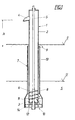
- a melt removal device for feeding casting machines or the like has one in the melt bath S one not shown Melting furnace immersed melt feed pump 1, which consists of a Pump tube 2 with a lower melt inlet 3 and an upper melt outlet 4 and one running inside the pump tube 2, via a Not shown drive motor driven pump shaft 5 with a Screw conveyor above the melt inlet 3 as a pump rotor 6, so that when the pump shaft rotates 5 melt through the melt inlet 3 sucked in and pumped up via the pump tube 2 to the melt outlet 4 becomes.
- Melting furnace immersed melt feed pump 1 which consists of a Pump tube 2 with a lower melt inlet 3 and an upper melt outlet 4 and one running inside the pump tube 2, via a Not shown drive motor driven pump shaft 5 with a Screw conveyor above the melt inlet 3 as a pump rotor 6, so that when the pump shaft rotates 5 melt through the melt inlet 3 sucked in and pumped up via the pump tube 2 to the melt outlet 4 becomes.
- the melt feed pump is to ensure that the melt can be removed without any problems a loading device 7 for keeping the delivery head constant upstream which charging device the pump tube 2 with the melt inlet 3 receiving loading container 8 and one up to the loading container a melt overflow 9 determining the loading height
- Charge pump 10 includes, so that by the charging device 7 for the melt pump 1 a by the height difference between the melt outlet 4 and melt overflow 9 resulting constant delivery head h is ensured, the overflow 9 in the range of the maximum melt level O des Melting bath S lies.
- the loading container 8 from a chamber 11 surrounding the melt inlet 3 with a lower one Intake opening 12 and a towering, forming the melt overflow 9
- Riser pipe 13 Chamber 11 and riser pipe 13 are coaxial with pump pipe 2 and the charge pump 10 also has a coaxial to the pump rotor 6
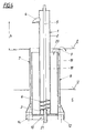
- melt feed pump If the melt feed pump is started up, this takes place simultaneously with the pump rotor 6 also the drive of the charge pump 10, which over their Loading rotor 14 promotes melt from the melt bath S into the chamber 11 and is dimensioned in its performance so that despite the by the melt pump 1 removed melt quantity an excess of melt through the Riser pipe 13 raised to the overflow 9 and for overflow and backflow is brought into the melt bath.
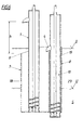
- a backflow valve 15 assigned to the suction opening 12 in the opposite direction to the suction direction occluding valve body 16, which is a part of the stroke adjustable Loading rotor 14 (FIG. 2) or its own valve plate 17 (FIG. 3) can be in the event of an interruption in the charge pump operation, a backflow of the Prevents melt from the riser 13.
- the loading container 8 the charging device 7 two sub-containers, one receiving the pump tube 2, charging part 18 closed on the bottom and a charging pump 10 receiving the lower suction opening 12 having filling part 19, the Filling part and the loading part in flow connection with one another via an overflow edge 20 stand and the filling part 19 forms the melt overflow 9.
- the melt pool S turns 10 into the charge pump Filling part 19 pumped until on the one hand over the overflow edge 20 the loading part 18 filled and on the other hand via the melt overflow 9 into the melt bath flows back.
- This becomes constant over the melt overflow 9 Delivery head h ensured for melt removal and also prevented the loading part 18 a drop in the loading height below that caused by the overflow edge 20 predetermined measure also during a pump standstill.
- FIG. 5 also shows a loading container 8 with a loading part 18 and a filling part 19, loading and filling part are arranged side by side and with one another via an overflow edge 20 to be in flow communication.
- the charging section is melt-filled via the filling section and the filling part 19 determines the constant with its melt overflow 9 Delivery head h for melt removal.
- the charge pump 10 one below the Loading part 14 at the extended end 21 of the pump shaft 5 loading rotor 5 is a to the melt feed pump in the embodiment of FIG 1 parallel charge pump 10 with its own drive shaft 22 and suitable Loading rotor 14 used in the filling part 19, so that by an independent Charge pump control of the loading operation exactly adapted to the removal operation can be.
- FIG. 6 is an embodiment similar to the embodiment of FIG. 5 with loading and filling parts 18, 19 arranged side by side proceed, the possibility being indicated as a charge pump 10 one with the Feed pump 1 to use the same pump 23, the melt outlet 4 in the Charging part 18 opens out.
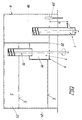
- the charging device 7 can also directly in a melting furnace 24 may be installed, the loading container 8 of the loading device 7 is integrated in the storage space 25 of the melting furnace 24 and with his charging part 18 one separated from the storage space 25, via the filling part 19 forms a removal chamber connected to the storage space 25.
- the charge pump 10 conveys melt the storage space 25 in the filling part 19, from where this melt over the Overflow edge 20 reaches the loading part 18 and for the melt removal by the feed pump 1 at a largely constant melt level is held, which in turn ensures a constant delivery head h.
- a melt level measuring device 26 can the charge pump 10 with regard to its drive depending on the melting level the removal chamber are controlled so that a fine tuning of the Loading operation to the removal operation is possible.
Landscapes
- Engineering & Computer Science (AREA)
- Mechanical Engineering (AREA)
- General Engineering & Computer Science (AREA)
- Structures Of Non-Positive Displacement Pumps (AREA)
Abstract
Description
- Fig. 1 bis 7
- sieben Ausführungsbeispiele einer erfindungsgemäßen Schmelzenentnahmevorrichtung jeweils an Hand eines Axialschnittes.
Claims (13)
- Schmelzenentnahmevorrichtung für Schmelzenöfen zur Beschickung von Gießmaschinen mit einer Schmelzenförderpumpe (1)aus einem einen unteren Schmelzeneinlauf (3) und einen oberen Schmelzenauslauf (4) bildenden Pumpenrohr (2) und einer innerhalb des Pumpenrohres (2) verlaufenden, einen Pumpenrotor (6) tragenden Pumpenwelle (5), dadurch gekennzeichnet, daß der Schmelzenförderpumpe (1) eine Ladeeinrichtung (7) zum Konstanthalten der Förderhöhe (h) vorgeordnet ist, welche Ladeeinrichtung (7) einen das Pumpenrohr (2) mit dem Schmelzeneinlauf (3) aufnehmenden Ladebehälter (8) und eine den Ladebehälter (8) bis zu einem die Ladehöhe bestimmenden Schmelzenüberlauf (9) schmelzenbefüllbare Ladepumpe (10) umfaßt, wobei die Förderleistung der Ladepumpe (10) die der Förderpumpe (1) übersteigt.
- Schmelzenentnahmevorrichtung nach Anspruch 1, dadurch gekennzeichnet, daß der Ladebehälter (8) aus einer den Schmelzeneinlauf (3) umgebenden Kammer (11) mit einer unteren Ansaugöffnung (12) und einem hochragenden, den Schmelzenüberlauf (9) bildenden Steigrohr (13) besteht und die Ladepumpe (10) einen im Ansaugöffnungsbereich (12) sitzenden Laderotor (14) aufweist.
- Schmelzenentnahmevorrichtung nach Anspruch 2, dadurch gekennzeichnet, daß der Ansaugöffnung (12) ein Rückströmventil (15) mit einem die Ansaugöffnung (12) gegensinnig zur Ansaugrichtung verschließenden Ventilkörper (16, 17) zugeordnet ist.
- Schmelzenentnahmevorrichtung nach Anspruch 3, dadurch gekennzeichnet, daß der oberhalb der Ansaugöffnung (12) hubverstellbar angeordnete Laderohr (14) selbst den Ventilkörper (16) bildet.
- Schmelzenentnahmevorrichtung nach einem der Ansprüche 2 bis 4, dadurch gekennzeichnet, daß der Ladebehälter (8) koaxial zum Pumpenrohr (2) angeordnet ist.
- Schmelzenentnahmevorrichtung nach einem der Ansprüche 2 bis 5, dadurch gekennzeichnet, daß die Pumpenwelle (5) nach unten aus dem Pumpenrohr (2) herausgeführt ist und mit ihrem vorragenden Ende als Antriebswelle für den Laderotor (14) dient.
- Schmelzenentnahmevorrichtung nach einem der Ansprüche 2 bis 5, dadurch gekennzeichnet, daß der Laderotor auf einer eigenen, durch die hohle Pumpenwelle geführten Antriebswelle sitzt.
- Schmelzenentnahmevorrichtung nach Anspruch 1, dadurch gekennzeichnet, daß der Ladebehälter (8) zwei Teilbehälter, einen das Pumpenrohr (2) aufnehmenden, bodenseits geschlossenen Ladeteil (18) und einen die Ladepumpe (10) aufnehmenden, die untere Ansaugöffnung (12) aufweisenden Befüllteil (19), umfaßt, wobei Befüllteil und Ladeteil über eine Überströmkante (20) miteinander in Strömungsverbindung stehen und der Befüllteil (19) den Schmelzenüberlauf (9) bildet.
- Schmelzenentnahmevorrichtung nach Anspruch 8, dadurch gekennzeichnet, daß Ladeteil (18) und Befüllteil (19) koaxial zum Pumpenrohr (2) angeordnet sind und der Befüllteil (19) den Ladeteil (18) umgibt, wobei die Ladepumpe (10) einen unterhalb des Ladeteils (18), auf einer aus dem Ladeteil herausgeführten Antriebswelle sitzenden Laderotor (24) aufweist.
- Schmelzenentnahmevorrichtung nach Anspruch 8, dadurch gekennzeichnet, daß Ladeteil (18) und Befüllteil (19) nebeneinander angeordnet sind und die Ladepumpe (10) des Befüllteils (19) eine zur Pumpenwelle (5) parallele Antriebswelle (22) mit einem unteren Laderotor (14) aufweist.
- Schmelzenentnahmevorrichtung nach Anspruch 10, dadurch gekennzeichnet, daß der Befüllteil (19) eine der Schmelzenförderpumpe (1) ähnliche Pumpe (23) als Ladepumpe (10) aufnimmt, deren Schmelzenauslauf (4) vorzugsweise in den Ladeteil (18) ausmündet.
- Schmelzenentnahmevorrichtung nach Anspruch 8, dadurch gekennzeichnet, daß der Ladebehälter (8) in einen Schmelzenofen (24) eingebaut ist, wobei der Ladeteil (18) eine vom Speicherraum (25) des Schmelzenofens (24) abgetrennte, über den Befüllteil (19) an den Speicherraum (25) angeschlossene Entnahmekammer bildet.
- Schmelzenentnahmevorrichtung nach Anspruch 12, dadurch gekennzeichnet, daß im Ladeteil (18) eine Schmelzenniveau-Meßeinrichtung (26) vorgesehen und der Ladepumpenantrieb in Abhängigkeit vom Schmelzenniveau des Ladeteils (19) ansteuerbar ist.
Priority Applications (2)
| Application Number | Priority Date | Filing Date | Title |
|---|---|---|---|
| DE50011444T DE50011444D1 (de) | 2000-03-02 | 2000-03-02 | Schmelzenentnahmevorrichtung für Schmelzenöfen zur Beschickung von Giessmaschinen |
| EP20000890065 EP1130266B1 (de) | 2000-03-02 | 2000-03-02 | Schmelzenentnahmevorrichtung für Schmelzenöfen zur Beschickung von Giessmaschinen |
Applications Claiming Priority (1)
| Application Number | Priority Date | Filing Date | Title |
|---|---|---|---|
| EP20000890065 EP1130266B1 (de) | 2000-03-02 | 2000-03-02 | Schmelzenentnahmevorrichtung für Schmelzenöfen zur Beschickung von Giessmaschinen |
Publications (2)
| Publication Number | Publication Date |
|---|---|
| EP1130266A1 true EP1130266A1 (de) | 2001-09-05 |
| EP1130266B1 EP1130266B1 (de) | 2005-10-26 |
Family
ID=8175912
Family Applications (1)
| Application Number | Title | Priority Date | Filing Date |
|---|---|---|---|
| EP20000890065 Expired - Lifetime EP1130266B1 (de) | 2000-03-02 | 2000-03-02 | Schmelzenentnahmevorrichtung für Schmelzenöfen zur Beschickung von Giessmaschinen |
Country Status (2)
| Country | Link |
|---|---|
| EP (1) | EP1130266B1 (de) |
| DE (1) | DE50011444D1 (de) |
Citations (6)
| Publication number | Priority date | Publication date | Assignee | Title |
|---|---|---|---|---|
| US4030538A (en) * | 1975-07-07 | 1977-06-21 | Groupement pour les Activities Atomiques et Advancees "GAAA" S.A. | Device for adjusting the quantity of molten metal used in pressure casting |
| US4398589A (en) * | 1981-09-25 | 1983-08-16 | General Electric Company | Pumping and metering device for fluid metals using electromagnetic pump |
| US5240063A (en) * | 1989-10-20 | 1993-08-31 | Hopwood Robert T | Casting apparatus for connecting a battery plate to a metal strap |
| US5427501A (en) * | 1994-05-03 | 1995-06-27 | Parker-Hannifin Corporation | Fuel pump impeller with pump down extension |
| DE4420655A1 (de) * | 1994-06-14 | 1995-12-21 | Karl Ley Fa | Fördervorrichtung für NE-Metallschmelzen |
| DE19541093A1 (de) * | 1995-11-03 | 1997-05-07 | Michael Heider | Pumpvorrichtung für einen Schmelzofen zum Fördern von flüssigen Metallegierungen |
-
2000
- 2000-03-02 EP EP20000890065 patent/EP1130266B1/de not_active Expired - Lifetime
- 2000-03-02 DE DE50011444T patent/DE50011444D1/de not_active Expired - Fee Related
Patent Citations (6)
| Publication number | Priority date | Publication date | Assignee | Title |
|---|---|---|---|---|
| US4030538A (en) * | 1975-07-07 | 1977-06-21 | Groupement pour les Activities Atomiques et Advancees "GAAA" S.A. | Device for adjusting the quantity of molten metal used in pressure casting |
| US4398589A (en) * | 1981-09-25 | 1983-08-16 | General Electric Company | Pumping and metering device for fluid metals using electromagnetic pump |
| US5240063A (en) * | 1989-10-20 | 1993-08-31 | Hopwood Robert T | Casting apparatus for connecting a battery plate to a metal strap |
| US5427501A (en) * | 1994-05-03 | 1995-06-27 | Parker-Hannifin Corporation | Fuel pump impeller with pump down extension |
| DE4420655A1 (de) * | 1994-06-14 | 1995-12-21 | Karl Ley Fa | Fördervorrichtung für NE-Metallschmelzen |
| DE19541093A1 (de) * | 1995-11-03 | 1997-05-07 | Michael Heider | Pumpvorrichtung für einen Schmelzofen zum Fördern von flüssigen Metallegierungen |
Also Published As
| Publication number | Publication date |
|---|---|
| EP1130266B1 (de) | 2005-10-26 |
| DE50011444D1 (de) | 2005-12-01 |
Similar Documents
| Publication | Publication Date | Title |
|---|---|---|
| DE2520732C2 (de) | Verfahren und Vorrichtung zur Steuerung der Bewegung einer Saugvorrichtung | |
| EP0711616B1 (de) | Vorrichtung zum Giessen von Metallen | |
| DE60300151T2 (de) | Verfahren und Vorrichtung zum Zuführen von Prozessflüssigkeit zu einer Werkzeugmaschine | |
| DE2417689A1 (de) | Verfahren und anlage zur kontinuierlichen und regelbaren schlammabsaugung aus einem klaerbecken | |
| DE19541093A1 (de) | Pumpvorrichtung für einen Schmelzofen zum Fördern von flüssigen Metallegierungen | |
| DE10310486A1 (de) | Obengeführtes Rückflussleitungssystem | |
| EP1486277B1 (de) | Vorrichtung zum Beschicken von Giesseinrichtungen mit Metallschmelze | |
| AT396680B (de) | Vorrichtung zum entfernen einer auf einer grundwasseroberfläche schwimmenden, flüssigen phase mittels eines in einen brunnenschacht absenkbaren behälters | |
| EP1130266B1 (de) | Schmelzenentnahmevorrichtung für Schmelzenöfen zur Beschickung von Giessmaschinen | |
| DE20022226U1 (de) | Schmelzenentnahmevorrichtung für Schmelzenöfen zur Beschickung von Gießmaschinen | |
| DE112015000451T5 (de) | Selbstreinigender Zentrifugalabscheider | |
| DE69321076T2 (de) | Dosiervorrichtung für flüssiges Magnesium | |
| EP2335897A1 (de) | Vorrichtung zur Aufbereitung einer kühl- und Spülflüssigkeit und Steuerungsverfahren für eine Aufbereitungsvorrichtung | |
| AT407232B (de) | Schmelzenentnahmevorrichtung für schmelzenöfen zur beschickung von giessmaschinen | |
| EP2298972A1 (de) | Spinnereimaschine mit Ölversorgungseinrichtung für wenigstens eine Spinnspindel | |
| DE3050183C2 (de) | Dosiereinrichtung zum Fördern von flüssigem Metall | |
| DE3023261C2 (de) | Mundstück für das Ende einer Förderleitung einer Dosiereinrichtung zum Fördern von flüssigem Metall | |
| DE2548672A1 (de) | Vorrichtung zur erzeugung einer kuenstlichen schwerkraft in fluessigkeiten | |
| US6306338B1 (en) | Melt withdrawal device for melt furnaces for charging casting machines | |
| DE279367C (de) | ||
| DE1245049B (de) | Vorrichtung zur dosierten Abgabe schmelzfluessiger Metalle aus einem Behaelter | |
| AT248041B (de) | Einrichtung zum selbsttätigen Abgießen dosierter Portionen flüssigen Metalls aus einem Vorratsbehälter | |
| DE3012047A1 (de) | Dosiereinrichtung zum foerdern von fluessigem metall | |
| DE2061168A1 (de) | Verfahren zum Steuern einer elektromagnetisch betaetigten Metallgiessvorrichtung | |
| DE3137050C2 (de) | Entladungsbearbeitungsvorrichtung |
Legal Events
| Date | Code | Title | Description |
|---|---|---|---|
| PUAI | Public reference made under article 153(3) epc to a published international application that has entered the european phase |
Free format text: ORIGINAL CODE: 0009012 |
|
| AK | Designated contracting states |
Kind code of ref document: A1 Designated state(s): AT BE CH CY DE DK ES FI FR GB GR IE IT LI LU MC NL PT SE |
|
| AX | Request for extension of the european patent |
Free format text: AL;LT;LV;MK;RO;SI |
|
| 17P | Request for examination filed |
Effective date: 20020305 |
|
| AKX | Designation fees paid |
Free format text: DE ES FR GB IT |
|
| GRAP | Despatch of communication of intention to grant a patent |
Free format text: ORIGINAL CODE: EPIDOSNIGR1 |
|
| GRAS | Grant fee paid |
Free format text: ORIGINAL CODE: EPIDOSNIGR3 |
|
| GRAA | (expected) grant |
Free format text: ORIGINAL CODE: 0009210 |
|
| AK | Designated contracting states |
Kind code of ref document: B1 Designated state(s): DE ES FR GB IT |
|
| PG25 | Lapsed in a contracting state [announced via postgrant information from national office to epo] |
Ref country code: IT Free format text: LAPSE BECAUSE OF FAILURE TO SUBMIT A TRANSLATION OF THE DESCRIPTION OR TO PAY THE FEE WITHIN THE PRESCRIBED TIME-LIMIT;WARNING: LAPSES OF ITALIAN PATENTS WITH EFFECTIVE DATE BEFORE 2007 MAY HAVE OCCURRED AT ANY TIME BEFORE 2007. THE CORRECT EFFECTIVE DATE MAY BE DIFFERENT FROM THE ONE RECORDED. Effective date: 20051026 Ref country code: GB Free format text: LAPSE BECAUSE OF FAILURE TO SUBMIT A TRANSLATION OF THE DESCRIPTION OR TO PAY THE FEE WITHIN THE PRESCRIBED TIME-LIMIT Effective date: 20051026 |
|
| REG | Reference to a national code |
Ref country code: GB Ref legal event code: FG4D Free format text: NOT ENGLISH |
|
| REF | Corresponds to: |
Ref document number: 50011444 Country of ref document: DE Date of ref document: 20051201 Kind code of ref document: P |
|
| PG25 | Lapsed in a contracting state [announced via postgrant information from national office to epo] |
Ref country code: ES Free format text: LAPSE BECAUSE OF FAILURE TO SUBMIT A TRANSLATION OF THE DESCRIPTION OR TO PAY THE FEE WITHIN THE PRESCRIBED TIME-LIMIT Effective date: 20060206 |
|
| PGFP | Annual fee paid to national office [announced via postgrant information from national office to epo] |
Ref country code: DE Payment date: 20060511 Year of fee payment: 7 |
|
| GBV | Gb: ep patent (uk) treated as always having been void in accordance with gb section 77(7)/1977 [no translation filed] |
Effective date: 20051026 |
|
| PLBE | No opposition filed within time limit |
Free format text: ORIGINAL CODE: 0009261 |
|
| STAA | Information on the status of an ep patent application or granted ep patent |
Free format text: STATUS: NO OPPOSITION FILED WITHIN TIME LIMIT |
|
| 26N | No opposition filed |
Effective date: 20060727 |
|
| EN | Fr: translation not filed | ||
| PG25 | Lapsed in a contracting state [announced via postgrant information from national office to epo] |
Ref country code: FR Free format text: LAPSE BECAUSE OF FAILURE TO SUBMIT A TRANSLATION OF THE DESCRIPTION OR TO PAY THE FEE WITHIN THE PRESCRIBED TIME-LIMIT Effective date: 20061215 |
|
| PG25 | Lapsed in a contracting state [announced via postgrant information from national office to epo] |
Ref country code: DE Free format text: LAPSE BECAUSE OF NON-PAYMENT OF DUE FEES Effective date: 20071002 |
|
| PG25 | Lapsed in a contracting state [announced via postgrant information from national office to epo] |
Ref country code: FR Free format text: LAPSE BECAUSE OF FAILURE TO SUBMIT A TRANSLATION OF THE DESCRIPTION OR TO PAY THE FEE WITHIN THE PRESCRIBED TIME-LIMIT Effective date: 20051026 |