EP1130194A2 - Une valve de distribution de fluides - Google Patents
Une valve de distribution de fluides Download PDFInfo
- Publication number
- EP1130194A2 EP1130194A2 EP01500006A EP01500006A EP1130194A2 EP 1130194 A2 EP1130194 A2 EP 1130194A2 EP 01500006 A EP01500006 A EP 01500006A EP 01500006 A EP01500006 A EP 01500006A EP 1130194 A2 EP1130194 A2 EP 1130194A2
- Authority
- EP
- European Patent Office
- Prior art keywords
- bonnet
- fluid
- valve
- rotor
- distributor valve
- Prior art date
- Legal status (The legal status is an assumption and is not a legal conclusion. Google has not performed a legal analysis and makes no representation as to the accuracy of the status listed.)
- Granted
Links
Images
Classifications
-
- E—FIXED CONSTRUCTIONS
- E04—BUILDING
- E04H—BUILDINGS OR LIKE STRUCTURES FOR PARTICULAR PURPOSES; SWIMMING OR SPLASH BATHS OR POOLS; MASTS; FENCING; TENTS OR CANOPIES, IN GENERAL
- E04H4/00—Swimming or splash baths or pools
- E04H4/14—Parts, details or accessories not otherwise provided for
- E04H4/16—Parts, details or accessories not otherwise provided for specially adapted for cleaning
- E04H4/169—Pool nozzles
-
- F—MECHANICAL ENGINEERING; LIGHTING; HEATING; WEAPONS; BLASTING
- F16—ENGINEERING ELEMENTS AND UNITS; GENERAL MEASURES FOR PRODUCING AND MAINTAINING EFFECTIVE FUNCTIONING OF MACHINES OR INSTALLATIONS; THERMAL INSULATION IN GENERAL
- F16K—VALVES; TAPS; COCKS; ACTUATING-FLOATS; DEVICES FOR VENTING OR AERATING
- F16K11/00—Multiple-way valves, e.g. mixing valves; Pipe fittings incorporating such valves
- F16K11/10—Multiple-way valves, e.g. mixing valves; Pipe fittings incorporating such valves with two or more closure members not moving as a unit
- F16K11/14—Multiple-way valves, e.g. mixing valves; Pipe fittings incorporating such valves with two or more closure members not moving as a unit operated by one actuating member, e.g. a handle
- F16K11/16—Multiple-way valves, e.g. mixing valves; Pipe fittings incorporating such valves with two or more closure members not moving as a unit operated by one actuating member, e.g. a handle which only slides, or only turns, or only swings in one plane
- F16K11/163—Multiple-way valves, e.g. mixing valves; Pipe fittings incorporating such valves with two or more closure members not moving as a unit operated by one actuating member, e.g. a handle which only slides, or only turns, or only swings in one plane only turns
-
- Y—GENERAL TAGGING OF NEW TECHNOLOGICAL DEVELOPMENTS; GENERAL TAGGING OF CROSS-SECTIONAL TECHNOLOGIES SPANNING OVER SEVERAL SECTIONS OF THE IPC; TECHNICAL SUBJECTS COVERED BY FORMER USPC CROSS-REFERENCE ART COLLECTIONS [XRACs] AND DIGESTS
- Y10—TECHNICAL SUBJECTS COVERED BY FORMER USPC
- Y10T—TECHNICAL SUBJECTS COVERED BY FORMER US CLASSIFICATION
- Y10T137/00—Fluid handling
- Y10T137/2496—Self-proportioning or correlating systems
- Y10T137/2559—Self-controlled branched flow systems
- Y10T137/265—Plural outflows
- Y10T137/2668—Alternately or successively substituted outflow
- Y10T137/2688—Flow rate responsive
- Y10T137/269—Flow sensing turbine
-
- Y—GENERAL TAGGING OF NEW TECHNOLOGICAL DEVELOPMENTS; GENERAL TAGGING OF CROSS-SECTIONAL TECHNOLOGIES SPANNING OVER SEVERAL SECTIONS OF THE IPC; TECHNICAL SUBJECTS COVERED BY FORMER USPC CROSS-REFERENCE ART COLLECTIONS [XRACs] AND DIGESTS
- Y10—TECHNICAL SUBJECTS COVERED BY FORMER USPC
- Y10T—TECHNICAL SUBJECTS COVERED BY FORMER US CLASSIFICATION
- Y10T137/00—Fluid handling
- Y10T137/8593—Systems
- Y10T137/86389—Programmer or timer
- Y10T137/86405—Repeating cycle
- Y10T137/86413—Self-cycling
-
- Y—GENERAL TAGGING OF NEW TECHNOLOGICAL DEVELOPMENTS; GENERAL TAGGING OF CROSS-SECTIONAL TECHNOLOGIES SPANNING OVER SEVERAL SECTIONS OF THE IPC; TECHNICAL SUBJECTS COVERED BY FORMER USPC CROSS-REFERENCE ART COLLECTIONS [XRACs] AND DIGESTS
- Y10—TECHNICAL SUBJECTS COVERED BY FORMER USPC
- Y10T—TECHNICAL SUBJECTS COVERED BY FORMER US CLASSIFICATION
- Y10T137/00—Fluid handling
- Y10T137/8593—Systems
- Y10T137/86389—Programmer or timer
- Y10T137/86445—Plural, sequential, valve actuations
- Y10T137/86461—Variable cycle
-
- Y—GENERAL TAGGING OF NEW TECHNOLOGICAL DEVELOPMENTS; GENERAL TAGGING OF CROSS-SECTIONAL TECHNOLOGIES SPANNING OVER SEVERAL SECTIONS OF THE IPC; TECHNICAL SUBJECTS COVERED BY FORMER USPC CROSS-REFERENCE ART COLLECTIONS [XRACs] AND DIGESTS
- Y10—TECHNICAL SUBJECTS COVERED BY FORMER USPC
- Y10T—TECHNICAL SUBJECTS COVERED BY FORMER US CLASSIFICATION
- Y10T137/00—Fluid handling
- Y10T137/8593—Systems
- Y10T137/86911—Sequential distributor or collector type
Definitions
- the invention relates to a fluid distributor valve.
- this distributor valve can be used in different facilities and for different purposes it has been preferably provided to be used in conjunction with swimming pool bottom flushing devices, said devices comprising several nozzles installed in the swimming pool bottom and through which a water jet is radially ejected flush with said bottom.
- valves provided to fulfil said function have been commercially available for a number of years, said valves generally comprising a chamber with a water inlet opening and several water outlet openings (one for one or more nozzles), each of said openings comprising a stopper being actuated by means of a reducing gear acting by virtue of the action of the infeed water on a rotor with which said gear is engaged.
- This invention has as its object a valve sensibly improving the known valves, one of said improvements consisting in the presence of one only device with external control means allowing to control the time during which each outlet opening will be held open as well as to arrest the valve in a given position wherein one only outlet opening is held open.
- Another of the advantages consists in closing each of the outlet openings or orifices by means of a respective flap, said flaps allowing to assure that a flap won't be closed till the next one is opened, said flaps having a flat seal assuring a tight closure.
- the body and the bonnet forming the chamber are also advantageously joined together without for such a purpose requiring to use any tools whatsoever and by means of a bayonet lock, this latter being besides provided with a fast-fixed safety catch.
- a bayonet lock Upon removal of the bonnet the whole mechanism becomes visible, this facilitating the access to the interior of the valve in order to carry out its cleaning and maintenance.
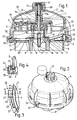
- the valve operation controlling and arresting device consists in a cylinder being integral with a central shaft being vertically shiftable from an external control means, said cylinder being slidable within a diffuser coaxially installed inside the rotor and forming part of an intermediary plate provided in the chamber, in such a way that when being lifted the cylinder does progressively close the openings of the diffuser and at the same time opens the openings provided in the downwardly extending edge of said diffuser and directly communicating with the lower region of the chamber where the water outlet orifices have been provided.
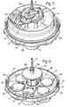
- the fluid distributor valve has a chamber 1 formed by a circular base body 2 provided to be closed by means of a domed bonnet 3, in said chamber being rotatably installed an intermediary plate 4 fitted around a vertical, central shaft 5 around which a rotor 6 is also fitted in a freely rotatable arrangement, said rotor being actuated by virtue of the action of the fluid flowing into the valve through a bottom opening 7 centrally provided in said body 2, this latter having around said opening fluid outlet orifices 8 being closed by stoppers being each formed by a respective circular flap 9, said flaps being hinged at their innermost end by means of a pin 10 fitting into corresponding forked protrusions 11 of the top surface of body 2.
- flaps 9 are sequentially raised as they are prised at their end opposite to that of their hinged connection as a ramp 12 passes underneath said flaps, said ramp being formed on the inside of the bottom edge of the periphery 13 of the intermediary plate 4, this latter having fitted on its top surface a reducing gear 15 whose first gear wheel 15a meshes with pinion 6a provided at the end of a top tubular shaft 6b of rotor 6, whereas the last wheel 15b of this gear meshes with an internal gear rim 3a provided on the inner periphery of bonnet 3.
- This valve comprises a central device by means of which the fluid passage from the bottom opening 7 towards the rotor 6 is controlled and can even be blocked if desired in order to thus adjust the time during which the flaps 9 will be held open, and also in order to keep only one of these flaps open when the valve has been arrested.
- This controlling and arresting device consists in a hollow cylinder 16 being integral with the central shaft 5, this latter being vertically shiftable by means of an external control means 17 to which said shaft is fitted at its upper end 5', whereas at its lower end 5" said shaft is supported and guided in a pocket 18 being axially integral with body 2 in its bottom opening 7.
- Said cylinder 16 is slidably fitted within a diffuser 19 coaxially installed inside rotor 6 and forming part of the intermediary plate 4, in such a way that when being lifted the cylinder 16 does progressively close the peripheral openings 19' of diffuser 19, and at the same time opens the openings 19" provided in the downwardly extending edge of said diffuser and directly communicating with that region of the valve where the outlet orifices 8 have been provided.
- Flaps 9 have at their outermost end an overhanging appendage 20 with a dihedral lower surface, said appendage being urged by said ramp 12, said flaps having attached to their lower edge a flat seal 21 assuring the tight closure of the fluid outlet orifices 8.
- Bonnet 3 is fitted to body 2 by means of a bayonet lock, for such a purpose the periphery of body 2 having the corresponding angular protrusions 22 provided to fit into the recesses 23 of the periphery of bonnet 3 to which a safety catch 24 has been fitted consisting of a strip 25 having a cross-section in the shape of an inverted L and being provided with a bottom rib 26 by way of a stop limiting the vertical shift of said strip, this latter having its inner surface provided with two horizontal grooves selectively engaging a rib provided on the periphery of bonnet 3 in order to thus fix the locked and unlocked positions in the fitting of bonnet 3 to body 2, in said locked position one of said protrusions 22 of the periphery of body 2 abutting against a peg 27 being integral with strip 25 and slidably fitted into a vertical orifice 28 of the very periphery of bonnet 3.
- the central shaft 5 is lifted and lowered by means of turning the control means 17 formed by an internally threaded knob by way of a nut sliding along an externally threaded neck 29 formed on the top end of bonnet 3.
- at 31 is shown a ring provided to be attached to body 2 and acting as an upper stop for the hinged connection of flaps 9 to said body.
Landscapes
- Engineering & Computer Science (AREA)
- Architecture (AREA)
- General Engineering & Computer Science (AREA)
- Civil Engineering (AREA)
- Structural Engineering (AREA)
- Mechanical Engineering (AREA)
- Mechanically-Actuated Valves (AREA)
- Multiple-Way Valves (AREA)
- Lift Valve (AREA)
- Sliding Valves (AREA)
- Physical Water Treatments (AREA)
- Solid-Sorbent Or Filter-Aiding Compositions (AREA)
- Fluid-Driven Valves (AREA)
- Preventing Unauthorised Actuation Of Valves (AREA)
- Physical Or Chemical Processes And Apparatus (AREA)
- Structures Of Non-Positive Displacement Pumps (AREA)
- Hydraulic Turbines (AREA)
Applications Claiming Priority (2)
| Application Number | Priority Date | Filing Date | Title |
|---|---|---|---|
| ES200000421U | 2000-02-21 | ||
| ES200000421U ES1045405Y (es) | 2000-02-21 | 2000-02-21 | Valvula distribuidora de fluidos. |
Publications (3)
| Publication Number | Publication Date |
|---|---|
| EP1130194A2 true EP1130194A2 (fr) | 2001-09-05 |
| EP1130194A3 EP1130194A3 (fr) | 2002-11-20 |
| EP1130194B1 EP1130194B1 (fr) | 2004-06-30 |
Family
ID=8492424
Family Applications (1)
| Application Number | Title | Priority Date | Filing Date |
|---|---|---|---|
| EP01500006A Expired - Lifetime EP1130194B1 (fr) | 2000-02-21 | 2001-01-10 | Une valve de distribution de fluides |
Country Status (6)
| Country | Link |
|---|---|
| US (1) | US6386232B2 (fr) |
| EP (1) | EP1130194B1 (fr) |
| AT (1) | ATE270369T1 (fr) |
| DE (1) | DE60104031T2 (fr) |
| ES (2) | ES1045405Y (fr) |
| TR (1) | TR200402031T4 (fr) |
Cited By (3)
| Publication number | Priority date | Publication date | Assignee | Title |
|---|---|---|---|---|
| EP1344879A3 (fr) * | 2002-03-13 | 2003-12-10 | Sacopa S.A.U. | Dispositif d'ouverture et de fermeture de l'ouverture d'une valve d'alimentation en fluide |
| EP1557508A1 (fr) * | 2004-01-21 | 2005-07-27 | Pentair Water Pool and Spa, Inc. | Vanne de secours pour une pression de sortie variable |
| WO2011119506A3 (fr) * | 2010-03-22 | 2014-06-19 | Blue Square Manufacturing, Llc | Vanne pour système de nettoyage de piscine de niveau |
Families Citing this family (12)
| Publication number | Priority date | Publication date | Assignee | Title |
|---|---|---|---|---|
| US20080169026A1 (en) * | 2007-01-11 | 2008-07-17 | Sanchez Terry J | Fluid diverter and method |
| US9341281B2 (en) | 2007-02-12 | 2016-05-17 | Colt Irrigation Llc | Fluid activated flow control apparatus |
| US8230871B2 (en) | 2007-02-12 | 2012-07-31 | Hurst James W | Fluid activated flow control system |
| US8820355B2 (en) * | 2009-01-30 | 2014-09-02 | Aspen Research, Ltd | Method and apparatus for cleaning pools with reduced energy consumption |
| US8256461B1 (en) * | 2009-01-30 | 2012-09-04 | Aspen Research, Ltd | Distribution valve and cam mechanism |
| US20110071799A1 (en) * | 2009-09-21 | 2011-03-24 | Per Arne Slotte | Grid models |
| US9222274B1 (en) * | 2012-09-05 | 2015-12-29 | Gsg Holdings, Inc. | Angled pool valve module |
| US10571937B1 (en) | 2014-01-23 | 2020-02-25 | Colt Irrigation, LLC | Valve control apparatus |
| US10088849B2 (en) | 2014-01-23 | 2018-10-02 | Colt Irrigation, LLC | Fluid activated flow control apparatus |
| US9599286B2 (en) | 2014-01-23 | 2017-03-21 | Colt Irrigation, LLC | Fluid activated flow control apparatus |
| US10641401B1 (en) * | 2016-02-26 | 2020-05-05 | Pool Patch LLC | Wearless multi-port water distribution valve assembly with bottom inlet |
| CN116220610B (zh) * | 2023-03-02 | 2023-09-19 | 江苏苏盐阀门机械有限公司 | 一种多通路采油井阀门 |
Citations (4)
| Publication number | Priority date | Publication date | Assignee | Title |
|---|---|---|---|---|
| US3779269A (en) * | 1972-01-20 | 1973-12-18 | H Gould | Flow switching valve |
| US4077424A (en) * | 1976-11-18 | 1978-03-07 | Wylain, Inc. | Liquid distributor valve assembly |
| US4570663A (en) * | 1983-04-22 | 1986-02-18 | Shasta Industries, Inc. | Distribution valve with dual cams to prevent uncontrolled excursions of valve balls |
| US4592379A (en) * | 1984-04-27 | 1986-06-03 | George J. Ghiz | Fluid distribution valve |
Family Cites Families (3)
| Publication number | Priority date | Publication date | Assignee | Title |
|---|---|---|---|---|
| US4313455A (en) * | 1979-11-14 | 1982-02-02 | Lester R. Mathews | Fluid routing device |
| US4817656A (en) * | 1988-03-01 | 1989-04-04 | Shasta Industries, Inc. | Multi-port distribution valve with gear driven rotary distribution cylinders |
| US6325087B1 (en) * | 2000-11-07 | 2001-12-04 | Shasta Industries, Inc. | Distribution valve and method |
-
2000
- 2000-02-21 ES ES200000421U patent/ES1045405Y/es not_active Expired - Fee Related
-
2001
- 2001-01-10 DE DE60104031T patent/DE60104031T2/de not_active Expired - Fee Related
- 2001-01-10 ES ES01500006T patent/ES2223757T3/es not_active Expired - Lifetime
- 2001-01-10 EP EP01500006A patent/EP1130194B1/fr not_active Expired - Lifetime
- 2001-01-10 TR TR2004/02031T patent/TR200402031T4/xx unknown
- 2001-01-10 AT AT01500006T patent/ATE270369T1/de not_active IP Right Cessation
- 2001-02-16 US US09/785,734 patent/US6386232B2/en not_active Expired - Fee Related
Patent Citations (4)
| Publication number | Priority date | Publication date | Assignee | Title |
|---|---|---|---|---|
| US3779269A (en) * | 1972-01-20 | 1973-12-18 | H Gould | Flow switching valve |
| US4077424A (en) * | 1976-11-18 | 1978-03-07 | Wylain, Inc. | Liquid distributor valve assembly |
| US4570663A (en) * | 1983-04-22 | 1986-02-18 | Shasta Industries, Inc. | Distribution valve with dual cams to prevent uncontrolled excursions of valve balls |
| US4592379A (en) * | 1984-04-27 | 1986-06-03 | George J. Ghiz | Fluid distribution valve |
Cited By (5)
| Publication number | Priority date | Publication date | Assignee | Title |
|---|---|---|---|---|
| EP1344879A3 (fr) * | 2002-03-13 | 2003-12-10 | Sacopa S.A.U. | Dispositif d'ouverture et de fermeture de l'ouverture d'une valve d'alimentation en fluide |
| EP1557508A1 (fr) * | 2004-01-21 | 2005-07-27 | Pentair Water Pool and Spa, Inc. | Vanne de secours pour une pression de sortie variable |
| US7373948B2 (en) | 2004-01-21 | 2008-05-20 | Pentair Water Pool And Spa, Inc. | Variable output pressure backup valve |
| EP2481870A3 (fr) * | 2004-01-21 | 2014-10-29 | Pentair Water Pool and Spa, Inc. | Vanne de secours pour une pression de sortie variable |
| WO2011119506A3 (fr) * | 2010-03-22 | 2014-06-19 | Blue Square Manufacturing, Llc | Vanne pour système de nettoyage de piscine de niveau |
Also Published As
| Publication number | Publication date |
|---|---|
| ES1045405U (es) | 2000-08-16 |
| US20010015228A1 (en) | 2001-08-23 |
| US6386232B2 (en) | 2002-05-14 |
| DE60104031D1 (de) | 2004-08-05 |
| ES1045405Y (es) | 2001-02-16 |
| ES2223757T3 (es) | 2005-03-01 |
| EP1130194B1 (fr) | 2004-06-30 |
| DE60104031T2 (de) | 2005-08-18 |
| ATE270369T1 (de) | 2004-07-15 |
| TR200402031T4 (tr) | 2004-10-21 |
| EP1130194A3 (fr) | 2002-11-20 |
Similar Documents
| Publication | Publication Date | Title |
|---|---|---|
| US6386232B2 (en) | Fluid distributor valve | |
| US4154679A (en) | Operating mechanism for swimming pool skimmer | |
| DE3690627C2 (fr) | ||
| ES2676882T3 (es) | Grifo de mezcla dotado de un filtro | |
| US20180036660A1 (en) | Pre-filtering device and method thereof | |
| US5349981A (en) | Drain valve for a flush tank | |
| US20080251604A1 (en) | Water Outlet Mouthpiece With Switch Jet Control Insert | |
| US4241759A (en) | Slow closing faucet | |
| CN102482009B (zh) | 分配盖 | |
| JPH0712247A (ja) | 洗浄弁フィルタ及びバイパス・オリフィス | |
| ES2350863T3 (es) | Dispositivo de accionamiento para una grifería de salida y grifería de salida con un dispositivo de accionamiento de este tipo así como un método para el montaje de una grifería de salida de este tipo. | |
| EP0726368B1 (fr) | Clapet de vidange pour citerne | |
| DE19748622A1 (de) | Spülkastenablaufgarnitur | |
| ES2217469T3 (es) | Estructura de descarga de una cisterna. | |
| EP1344879B1 (fr) | Dispositif d'ouverture et de fermeture de l'ouverture d'une valve d'alimentation en fluide | |
| EP2157342B1 (fr) | Dispositif pour l'ouverture et la fermeture de sorties d'une valve de distribution de liquide | |
| DE2658295B2 (de) | Kaffeekanne, insbesondere zur Verwendung in einer elektrischen Kaffeemaschine | |
| US1446710A (en) | Volume-reducing valve cap | |
| US2056103A (en) | Shower bath spray head | |
| KR102183571B1 (ko) | 세면대 팝업 밸브 | |
| US4316485A (en) | Single handle mixing valve with improved seat | |
| JPS592362Y2 (ja) | 過大流量防止装置付ガスコツク | |
| CN109518776B (zh) | 一种新型进水阀 | |
| KR200364715Y1 (ko) | 에어벤트 밸브 | |
| KR200231063Y1 (ko) | 실린더형 디스크 밸브 |
Legal Events
| Date | Code | Title | Description |
|---|---|---|---|
| PUAI | Public reference made under article 153(3) epc to a published international application that has entered the european phase |
Free format text: ORIGINAL CODE: 0009012 |
|
| AK | Designated contracting states |
Kind code of ref document: A2 Designated state(s): AT BE CH CY DE DK ES FI FR GB GR IE IT LI LU MC NL PT SE TR |
|
| AX | Request for extension of the european patent |
Free format text: AL;LT;LV;MK;RO;SI |
|
| PUAL | Search report despatched |
Free format text: ORIGINAL CODE: 0009013 |
|
| AK | Designated contracting states |
Kind code of ref document: A3 Designated state(s): AT BE CH CY DE DK ES FI FR GB GR IE IT LI LU MC NL PT SE TR |
|
| AX | Request for extension of the european patent |
Free format text: AL;LT;LV;MK;RO;SI |
|
| RIC1 | Information provided on ipc code assigned before grant |
Free format text: 7E 04H 4/16 A, 7F 16K 11/16 B |
|
| 17P | Request for examination filed |
Effective date: 20030428 |
|
| AKX | Designation fees paid |
Designated state(s): AT BE CH CY DE DK ES FI FR GB GR IE IT LI LU MC NL PT SE TR |
|
| 17Q | First examination report despatched |
Effective date: 20030717 |
|
| GRAP | Despatch of communication of intention to grant a patent |
Free format text: ORIGINAL CODE: EPIDOSNIGR1 |
|
| GRAS | Grant fee paid |
Free format text: ORIGINAL CODE: EPIDOSNIGR3 |
|
| GRAA | (expected) grant |
Free format text: ORIGINAL CODE: 0009210 |
|
| AK | Designated contracting states |
Kind code of ref document: B1 Designated state(s): AT BE CH CY DE DK ES FI FR GB GR IE IT LI LU MC NL PT SE TR |
|
| PG25 | Lapsed in a contracting state [announced via postgrant information from national office to epo] |
Ref country code: LI Free format text: LAPSE BECAUSE OF FAILURE TO SUBMIT A TRANSLATION OF THE DESCRIPTION OR TO PAY THE FEE WITHIN THE PRESCRIBED TIME-LIMIT Effective date: 20040630 Ref country code: FI Free format text: LAPSE BECAUSE OF FAILURE TO SUBMIT A TRANSLATION OF THE DESCRIPTION OR TO PAY THE FEE WITHIN THE PRESCRIBED TIME-LIMIT Effective date: 20040630 Ref country code: NL Free format text: LAPSE BECAUSE OF FAILURE TO SUBMIT A TRANSLATION OF THE DESCRIPTION OR TO PAY THE FEE WITHIN THE PRESCRIBED TIME-LIMIT Effective date: 20040630 Ref country code: BE Free format text: LAPSE BECAUSE OF FAILURE TO SUBMIT A TRANSLATION OF THE DESCRIPTION OR TO PAY THE FEE WITHIN THE PRESCRIBED TIME-LIMIT Effective date: 20040630 Ref country code: AT Free format text: LAPSE BECAUSE OF FAILURE TO SUBMIT A TRANSLATION OF THE DESCRIPTION OR TO PAY THE FEE WITHIN THE PRESCRIBED TIME-LIMIT Effective date: 20040630 Ref country code: CH Free format text: LAPSE BECAUSE OF FAILURE TO SUBMIT A TRANSLATION OF THE DESCRIPTION OR TO PAY THE FEE WITHIN THE PRESCRIBED TIME-LIMIT Effective date: 20040630 |
|
| REG | Reference to a national code |
Ref country code: GB Ref legal event code: FG4D Ref country code: CH Ref legal event code: EP |
|
| REG | Reference to a national code |
Ref country code: IE Ref legal event code: FG4D |
|
| REF | Corresponds to: |
Ref document number: 60104031 Country of ref document: DE Date of ref document: 20040805 Kind code of ref document: P |
|
| PG25 | Lapsed in a contracting state [announced via postgrant information from national office to epo] |
Ref country code: SE Free format text: LAPSE BECAUSE OF FAILURE TO SUBMIT A TRANSLATION OF THE DESCRIPTION OR TO PAY THE FEE WITHIN THE PRESCRIBED TIME-LIMIT Effective date: 20040930 Ref country code: DK Free format text: LAPSE BECAUSE OF FAILURE TO SUBMIT A TRANSLATION OF THE DESCRIPTION OR TO PAY THE FEE WITHIN THE PRESCRIBED TIME-LIMIT Effective date: 20040930 |
|
| REG | Reference to a national code |
Ref country code: GR Ref legal event code: EP Ref document number: 20040403109 Country of ref document: GR |
|
| NLV1 | Nl: lapsed or annulled due to failure to fulfill the requirements of art. 29p and 29m of the patents act | ||
| PG25 | Lapsed in a contracting state [announced via postgrant information from national office to epo] |
Ref country code: IT Free format text: LAPSE BECAUSE OF NON-PAYMENT OF DUE FEES Effective date: 20050110 Ref country code: CY Free format text: LAPSE BECAUSE OF FAILURE TO SUBMIT A TRANSLATION OF THE DESCRIPTION OR TO PAY THE FEE WITHIN THE PRESCRIBED TIME-LIMIT Effective date: 20050110 Ref country code: IE Free format text: LAPSE BECAUSE OF NON-PAYMENT OF DUE FEES Effective date: 20050110 |
|
| PGFP | Annual fee paid to national office [announced via postgrant information from national office to epo] |
Ref country code: TR Payment date: 20050110 Year of fee payment: 5 |
|
| REG | Reference to a national code |
Ref country code: CH Ref legal event code: PL |
|
| PG25 | Lapsed in a contracting state [announced via postgrant information from national office to epo] |
Ref country code: MC Free format text: LAPSE BECAUSE OF NON-PAYMENT OF DUE FEES Effective date: 20050131 |
|
| REG | Reference to a national code |
Ref country code: ES Ref legal event code: FG2A Ref document number: 2223757 Country of ref document: ES Kind code of ref document: T3 |
|
| ET | Fr: translation filed | ||
| PLBE | No opposition filed within time limit |
Free format text: ORIGINAL CODE: 0009261 |
|
| STAA | Information on the status of an ep patent application or granted ep patent |
Free format text: STATUS: NO OPPOSITION FILED WITHIN TIME LIMIT |
|
| 26N | No opposition filed |
Effective date: 20050331 |
|
| REG | Reference to a national code |
Ref country code: IE Ref legal event code: MM4A |
|
| PGFP | Annual fee paid to national office [announced via postgrant information from national office to epo] |
Ref country code: GB Payment date: 20051228 Year of fee payment: 6 Ref country code: GR Payment date: 20051228 Year of fee payment: 6 |
|
| PGFP | Annual fee paid to national office [announced via postgrant information from national office to epo] |
Ref country code: DE Payment date: 20060329 Year of fee payment: 6 |
|
| PG25 | Lapsed in a contracting state [announced via postgrant information from national office to epo] |
Ref country code: DE Free format text: LAPSE BECAUSE OF NON-PAYMENT OF DUE FEES Effective date: 20070801 |
|
| GBPC | Gb: european patent ceased through non-payment of renewal fee |
Effective date: 20070110 |
|
| PG25 | Lapsed in a contracting state [announced via postgrant information from national office to epo] |
Ref country code: GB Free format text: LAPSE BECAUSE OF NON-PAYMENT OF DUE FEES Effective date: 20070110 |
|
| PG25 | Lapsed in a contracting state [announced via postgrant information from national office to epo] |
Ref country code: PT Free format text: LAPSE BECAUSE OF NON-PAYMENT OF DUE FEES Effective date: 20041130 |
|
| PGFP | Annual fee paid to national office [announced via postgrant information from national office to epo] |
Ref country code: FR Payment date: 20070118 Year of fee payment: 7 |
|
| PG25 | Lapsed in a contracting state [announced via postgrant information from national office to epo] |
Ref country code: GR Free format text: LAPSE BECAUSE OF NON-PAYMENT OF DUE FEES Effective date: 20070802 |
|
| REG | Reference to a national code |
Ref country code: FR Ref legal event code: ST Effective date: 20081029 |
|
| PG25 | Lapsed in a contracting state [announced via postgrant information from national office to epo] |
Ref country code: FR Free format text: LAPSE BECAUSE OF NON-PAYMENT OF DUE FEES Effective date: 20080131 |
|
| PG25 | Lapsed in a contracting state [announced via postgrant information from national office to epo] |
Ref country code: TR Free format text: LAPSE BECAUSE OF FAILURE TO SUBMIT A TRANSLATION OF THE DESCRIPTION OR TO PAY THE FEE WITHIN THE PRESCRIBED TIME-LIMIT Effective date: 20040630 |
|
| PGFP | Annual fee paid to national office [announced via postgrant information from national office to epo] |
Ref country code: IT Payment date: 20070530 Year of fee payment: 7 |
|
| PGRI | Patent reinstated in contracting state [announced from national office to epo] |
Ref country code: IT Effective date: 20091201 |
|
| PGFP | Annual fee paid to national office [announced via postgrant information from national office to epo] |
Ref country code: ES Payment date: 20120210 Year of fee payment: 12 |
|
| PGRI | Patent reinstated in contracting state [announced from national office to epo] |
Ref country code: IT Effective date: 20091201 |
|
| REG | Reference to a national code |
Ref country code: ES Ref legal event code: FD2A Effective date: 20140519 |
|
| PG25 | Lapsed in a contracting state [announced via postgrant information from national office to epo] |
Ref country code: ES Free format text: LAPSE BECAUSE OF NON-PAYMENT OF DUE FEES Effective date: 20130111 |