EP1129999A2 - Method for making multiple overclad optical fiber preforms - Google Patents
Method for making multiple overclad optical fiber preforms Download PDFInfo
- Publication number
- EP1129999A2 EP1129999A2 EP01301433A EP01301433A EP1129999A2 EP 1129999 A2 EP1129999 A2 EP 1129999A2 EP 01301433 A EP01301433 A EP 01301433A EP 01301433 A EP01301433 A EP 01301433A EP 1129999 A2 EP1129999 A2 EP 1129999A2
- Authority
- EP
- European Patent Office
- Prior art keywords
- overclad
- preform
- tube
- overclad tube
- core rod
- Prior art date
- Legal status (The legal status is an assumption and is not a legal conclusion. Google has not performed a legal analysis and makes no representation as to the accuracy of the status listed.)
- Withdrawn
Links
Images


Classifications
-
- C—CHEMISTRY; METALLURGY
- C03—GLASS; MINERAL OR SLAG WOOL
- C03B—MANUFACTURE, SHAPING, OR SUPPLEMENTARY PROCESSES
- C03B37/00—Manufacture or treatment of flakes, fibres, or filaments from softened glass, minerals, or slags
- C03B37/01—Manufacture of glass fibres or filaments
- C03B37/012—Manufacture of preforms for drawing fibres or filaments
- C03B37/01205—Manufacture of preforms for drawing fibres or filaments starting from tubes, rods, fibres or filaments
- C03B37/01225—Means for changing or stabilising the shape, e.g. diameter, of tubes or rods in general, e.g. collapsing
- C03B37/0124—Means for reducing the diameter of rods or tubes by drawing, e.g. for preform draw-down
-
- C—CHEMISTRY; METALLURGY
- C03—GLASS; MINERAL OR SLAG WOOL
- C03B—MANUFACTURE, SHAPING, OR SUPPLEMENTARY PROCESSES
- C03B37/00—Manufacture or treatment of flakes, fibres, or filaments from softened glass, minerals, or slags
- C03B37/01—Manufacture of glass fibres or filaments
- C03B37/012—Manufacture of preforms for drawing fibres or filaments
- C03B37/01205—Manufacture of preforms for drawing fibres or filaments starting from tubes, rods, fibres or filaments
- C03B37/01211—Manufacture of preforms for drawing fibres or filaments starting from tubes, rods, fibres or filaments by inserting one or more rods or tubes into a tube
-
- C—CHEMISTRY; METALLURGY
- C03—GLASS; MINERAL OR SLAG WOOL
- C03B—MANUFACTURE, SHAPING, OR SUPPLEMENTARY PROCESSES
- C03B37/00—Manufacture or treatment of flakes, fibres, or filaments from softened glass, minerals, or slags
- C03B37/01—Manufacture of glass fibres or filaments
- C03B37/012—Manufacture of preforms for drawing fibres or filaments
- C03B37/01205—Manufacture of preforms for drawing fibres or filaments starting from tubes, rods, fibres or filaments
- C03B37/01225—Means for changing or stabilising the shape, e.g. diameter, of tubes or rods in general, e.g. collapsing
- C03B37/01248—Means for changing or stabilising the shape, e.g. diameter, of tubes or rods in general, e.g. collapsing by collapsing without drawing
-
- C—CHEMISTRY; METALLURGY
- C03—GLASS; MINERAL OR SLAG WOOL
- C03B—MANUFACTURE, SHAPING, OR SUPPLEMENTARY PROCESSES
- C03B37/00—Manufacture or treatment of flakes, fibres, or filaments from softened glass, minerals, or slags
- C03B37/01—Manufacture of glass fibres or filaments
- C03B37/02—Manufacture of glass fibres or filaments by drawing or extruding, e.g. direct drawing of molten glass from nozzles; Cooling fins therefor
- C03B37/025—Manufacture of glass fibres or filaments by drawing or extruding, e.g. direct drawing of molten glass from nozzles; Cooling fins therefor from reheated softened tubes, rods, fibres or filaments, e.g. drawing fibres from preforms
- C03B37/027—Fibres composed of different sorts of glass, e.g. glass optical fibres
- C03B37/02754—Solid fibres drawn from hollow preforms
-
- C—CHEMISTRY; METALLURGY
- C03—GLASS; MINERAL OR SLAG WOOL
- C03B—MANUFACTURE, SHAPING, OR SUPPLEMENTARY PROCESSES
- C03B2203/00—Fibre product details, e.g. structure, shape
- C03B2203/10—Internal structure or shape details
- C03B2203/22—Radial profile of refractive index, composition or softening point
- C03B2203/23—Double or multiple optical cladding profiles
-
- Y—GENERAL TAGGING OF NEW TECHNOLOGICAL DEVELOPMENTS; GENERAL TAGGING OF CROSS-SECTIONAL TECHNOLOGIES SPANNING OVER SEVERAL SECTIONS OF THE IPC; TECHNICAL SUBJECTS COVERED BY FORMER USPC CROSS-REFERENCE ART COLLECTIONS [XRACs] AND DIGESTS
- Y02—TECHNOLOGIES OR APPLICATIONS FOR MITIGATION OR ADAPTATION AGAINST CLIMATE CHANGE
- Y02P—CLIMATE CHANGE MITIGATION TECHNOLOGIES IN THE PRODUCTION OR PROCESSING OF GOODS
- Y02P40/00—Technologies relating to the processing of minerals
- Y02P40/50—Glass production, e.g. reusing waste heat during processing or shaping
- Y02P40/57—Improving the yield, e-g- reduction of reject rates
Definitions
- the invention relates to methods and apparatus for overcladding a glass rod. More particularly, the invention relates to Rod-In-Tube (RIT) methods and apparatus for overcladding a glass rod.
- RIT Rod-In-Tube
- Optical fibers typically are fabricated by heating and drawing a portion of an optical preform comprising a refractive core surrounded by a protective glass cladding.
- MCVD modified chemical vapor deposition
- VAD vapor axial deposition
- precursor gases such as SiCl 4 and GeCl 4 pass through a rotating substrate tube of silica glass.
- a torch heats the tube from the outside as the precursor gases pass therethrough, causing deposition of submicron-sized glass particles on the inside surface of the tube. Movement of the torch along the longitudinal axis of the tube in a plurality of passes builds up layer upon layer of glass to provide a preform tube. Once a suitable number of layers have been deposited, the preform tube is heated to cause it to collapse into a solid rod typically referred to as the preform, the preform rod, the core rod or the preform core rod.
- the preform core rod then is inserted into a glass overclad tube, which is collapsed onto the preform core rod using heat and a pressure gradient present about the overclad tube.
- Such process typically is referred to as the Rod-In-Tube (RIT) process.
- RIT Rod-In-Tube
- steps of the RIT process are repeated. More specifically, to produce optical fiber preforms having larger diameters, for example, 63 millimeters (mm) or larger, the RIT process is performed twice.
- a first overclad tube is collapsed onto the preform core rod using a conventional RIT process and then a second overclad tube is collapsed onto the existing overclad preform rod using a second RIT process.
- the resulting double-clad optical fiber preform is desirably larger than preforms made with a more conventional, single RIT overcladding process.
- preforms having larger diameters tend to yield more optical fiber drawn therefrom than smaller preforms. The increased yield thus improves productivity of preform manufacturing processes, as the number of preforms used per length of optical fiber is reduced, as are the associated set-up and installation times.
- the collapse of the overclad tube onto the preform core rod typically is performed while the overclad tube and the preform core rod are mounted in a vertical lathe.
- the collapse of the overclad tube on the preform core rod is performed in a draw tower furnace, which also is used to draw optical fiber from the resulting optical fiber preform.
- Such collapse is accomplished by inserting the preform core rod into an overclad tube and then moving the combined preform core rod and overclad tube coaxially through the draw tower furnace, which causes collapse of the overclad tube onto the preform core rod prior to the drawing of the fiber.
- Such technique often is referred to as Overclad During Draw (ODD).
- Embodiments of the invention include a method for making a multiple overclad optical fiber preform and making optical fiber therefrom.
- the method for making a multiple overclad optical fiber preform includes the steps of positioning a first overclad tube around a preform core rod, positioning at least one second overclad tube around the first overclad tube, and collectively heating the preform core, the first overclad tube and the one or more second overclad tubes under pressure to collapse the overclad tubes onto the preform core rod thus producing a multiple-clad optical fiber preform.
- Heating occurs either in a draw tower furnace, for example, as part of an Overclad During Draw (ODD) process, or, alternatively, by a separate heating source prior to introducing the preform into the draw tower, for example, as in a conventional Rod-In-Tube (RIT) process.
- the preform core rod is positioned into and substantially coaxial with the first overclad tube, for example, by inserting the distal end of the preform core rod into the proximal end of the first overclad tube and sealing the relative positions thereof.
- first overclad tube is positioned into and substantially coaxial with the one or more second overclad tubes, for example, by inserting the distal end of the first overclad tube into the proximal end of the second overclad tubes and sealing their respective positions.
- the method for making optical fiber from the multiple overclad preform further includes the step of drawing optical fiber as portions of the preform are being heated in the draw tower furnace, as per ODD processes.
- the multiple overclad preform is heated by a heating source external to the draw tower, for example, as in conventional RIT processes.
- the resulting multiple overclad preform then is moved to the draw tower and optical fiber subsequently is drawn therefrom.
- FIG. 1a an apparatus 10 (Fig. 1a), comprising a preform core rod 12 and an overclad tube 14, used to make an overclad preform 20 (Fig. 1b) according to a conventional Rod-In-Tube (RIT) process.
- the preform core rod 12 is positioned vertically within the overclad tube 14 prior to the collapse of the overclad tube 14 around the preform core rod 12.
- Fig. 1b illustrates the overclad preform 20 after the overclad tube 14 has been collapsed around the preform core rod 12.
- the preform core rod 12 is made by any suitable process, including conventional processes such as modified chemical vapor deposition (MCVD) or vapor axial deposition (VAD).
- MCVD modified chemical vapor deposition
- VAD vapor axial deposition
- the preform core rod 12 has a proximal end 22 and a distal end 24, and often is made with a handle 26 at the proximal end 22.
- the handle 26 facilitates maneuvering the preform core rod 12, for example, as the distal end 24 of the rod 12 is inserted into the overclad tube 14.
- the overclad tube 14 has a first or proximal end 32 into which the preform core rod 12 is inserted and a second or distal end 34 configured for mounting into a chuck or other appropriate holding device.
- An adjustable support rod 36 is positioned within the second end 34 of the overclad tube 14 to provide support for the preform core rod 12.
- the proximal end 22 of the preform core rod 12 is sealed off, for example, by a seal 42 or other appropriate means.
- a pressure gradient then is established across the region between the preform core rod 12 and the overclad tube 14, for example, by operably coupling a vacuum source 44 to the distal end of the overclad tube 14.
- the overclad tube 14 is heated while the pressure gradient is maintained across the region between the preform core rod 12 and the overclad tube 14, thus collapsing the overclad tube 14 around the preform core rod 12, for example, in accordance with a conventional Rod-In-Tube (RIT) process.
- the resulting overclad preform 20 is shown in Fig. 1b.
- At least one more subsequent overcladding process is performed if the final size of the optical fiber is desired to be larger. That is, once the first overclad tube is collapsed onto the preform core rod using a first conventional RIT process, a second overclad tube is collapsed onto the existing overclad preform 20 using a second conventional RIT process.
- the resulting double-clad or double overclad optical fiber preform is desirably larger than preforms made with a more conventional, single RIT overcladding process.
- overclad optical fiber preforms that typically have an outer diameter, for example, of approximately 50 millimeters (mm), using a single RIT process are made to have an outer diameter, for example, of approximately 80 mm, using a second RIT process.
- RIT processes include collapsing the overclad tube 14 on the preform core rod 12 in the furnace of the draw tower used for drawing optical fiber from the resulting overclad preform 20.
- ODD Overclad During Draw
- the preform core rod 12 is positioned, for example, vertically, within the overclad tube 14.
- a quartz disc 46 or other supporting or spacer means typically occupies the second or distal end 34 of the overclad tube 14.
- the proximal end 22 of the preform core rod 12 is sealed at the first or proximal end 32 of the overclad tube 14, for example, by the seal 42 or other appropriate sealing means.
- proximal end 22 of the preform core rod 12 and the proximal end 32 of the overclad tube 14 then are heated together to form a sealed, unitary structure.
- Fig. 2b shows one arrangement of the resulting overclad tube 14 having the preform core rod 12 sealingly positioned therein.
- the combined overclad tube 14 and preform core rod 12 then is moved through a draw tower furnace (not shown), beginning with the sealed proximal ends 22, 32.
- a draw tower furnace (not shown), beginning with the sealed proximal ends 22, 32.
- the overclad tube 14 gradually but completely collapses onto the preform core rod 12 prior to optical fiber being drawn from the resulting overclad preform.
- the ODD process is advantageous, for example, in that separate heat treatment needed for collapsing the overclad tube on the preform outside of the furnace (for example, on a lathe) is not needed because the draw tower furnace provides such heat. Also not needed is some of the separate set-up and tube preparation processing associated with separate heat treatment steps.
- Embodiments of the invention are based on the advantageous realization that the overcladding process times are improved and other efficiencies are gained by manufacturing dual, double or multiple overclad optical fiber preforms using an inventive overclad during draw (ODD) process.
- ODD overclad during draw
- other advantages include improved overclad layer structure and more efficient use of overclad tube materials.
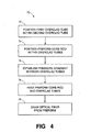
- FIGs. 3a-b shown are an apparatus 50 (Fig. 3a) for making a dual overclad optical fiber preform according to embodiments of the invention and the resulting double overclad tube 60 (Fig. 3b) with the preform core rod 12 sealingly positioned therein. Also, referring to Fig. 4, with continuing reference to Figs. 3a-b, shown is a simplified block diagram of a method 70 for making dual overclad optical fiber preforms and for drawing optical fiber therefrom.
- the inventive apparatus 50 shown in Fig. 3a includes a preform core rod 12, a first overclad tube 14 and a second overclad tube 56.
- the preform core rod 12 has a proximal end 22 with a handle 26 and a distal end 24.
- the first overclad tube 14 has a proximal end 32 and a distal end 34
- the second overclad tube 56 likewise has a proximal end 62 and a distal end 64.
- additional second overclad tubes are included. However, for purposes of discussion herein, only the first and second overclad tubes are shown in the Figs.
- One step 72 of the method 70 is to position the preform core rod 12 and the first overclad tube 14 within the second overclad tube 56, for example, by inserting the distal ends 24, 34 of the preform core rod 12 and the first overclad tube 14, respectively, into the proximal end 62 of the second overclad tube 56.
- the first overclad tube 14 typically will be shorter in length than the second overclad tube 56, although the final overall useful size of the preform does not differ disadvantageously from preforms made according to conventional techniques.
- Another step 74 of the method 70 is to position the preform core rod 12 within the overclad tubes, for example, by inserting the distal end 24 of the preform core rod 12 into the proximal end 32 of the first overclad tube 14.
- the handle 26 facilitates insertion of the preform core rod 12 into the first overclad tube 14.
- the preform core rod 12 and the first overclad tube 14 are dimensioned such that the outer diameter of the preform core rod 12 is within the range from approximately 0.50 millimeters (mm) to approximately 1.75 mm from the inner diameter of the first overclad tube 14.
- the preform core rod 12 and first overclad tube 14 are configured in such a way that, when the preform core rod 12 is positioned within the first overclad tube 14, the two are substantially coaxial with respect to one another.
- a support 46 such as a quartz disc or suitable spacer means supports both the preform core rod 12 and the first overclad tube 14, as shown. Support for shorter preform core rods is achieved, for example, using one or more quartz spacers in addition to the quartz disc 46. Also, it is possible for the first overclad tube 14 to be configured such that the quartz disc 46 is positioned therein for supporting the preform core rod 12 therein. Other supports including support rods are suitable for use in the inventive embodiments shown and described herein.
- the second overclad tube 56 is configured, for example, in such a way that the quartz disc 46 or other spacer means is positioned therein so as to supportably position the preform core rod 12 and the first overclad tube 14 with respect to one another.
- the distal end 64 of the second overclad tube 56 is configured for mounting into a chuck or other appropriate holding device, and thus has a reduced inner diameter, which is dimensioned to position the quartz disc 46 therein.
- the first and second overclad tubes are dimensioned such that the outer diameter of the first overclad tube 14 is within the range from approximately 0.50 mm to approximately 1.75 mm from the inner diameter of the second overclad tube 56.
- the preform core rod 12 and the overclad tubes are configured in such a way that, when positioned as shown, the three are substantially coaxial with respect to one another.
- a second seal or seal ring 58, or other suitable sealing means is used to maintain the relative position of the first overclad tube 14 with respect to the second overclad tube 56, for example, by sealing the proximal end 32 of the first overclad tube 14 to the proximal end 62 of the second overclad tube 56.
- the relative positions of the preform core rod 12, the first overclad tube 14 and the second overclad tube 56 all are maintained with respect to one another and have been sealed off at their proximal ends.
- proximal ends of the preform core rod 12, the first overclad tube 14 and the second overclad tube 56 then are heated or otherwise formed together in a manner that results in a sealed, unitary structure.
- the resulting structure is shown, for example, in Fig. 3b as an apparatus 60.
- Another step 76 in the method 70 is to establish a pressure gradient across the sealed area, for example, using a vacuum source operably connected across the distal ends of the first overclad tube 14 and the second overclad tube 56.
- the established pressure gradient is such that the pressure outside the second overclad tube 56 is substantially greater than the pressure inside the second overclad tube 56, and the pressure outside the first overclad tube 14 is substantially greater than the pressure inside the first overclad tube 14.
- the pressure gradient is within the range from approximately 0.25 to approximately 0.50 atmospheric pressure.
- Another step 78 in the method 70 is to heat the apparatus 60 comprising the preform core rod 12 and the overclad tubes, for example, within the range from approximately 1600-1700° C.
- the heating step 78 applies heat, for example, to successive axial portions of the apparatus 60, that is, along the length of the apparatus 60 from the proximal ends to the distal ends.
- the heating step 78 applies heat simultaneously to most if not all portions of the combined preform and dual overclad tube apparatus 60. Such simultaneous heating generally is indicative of heating in conventional RIT processes.
- the heating step 78 causes the overclad tubes to collapse onto the preform core rod 12 (Fig. 3b generally illustrates the apparatus 60 prior to such collapsing).
- a dual or multiple clad optical fiber preform is formed using a single rather than double RIT process. That is, one heating and collapsing step is used rather than conventional methods that typically require two separate heating and collapsing steps, that is, a first heating and collapsing step and then a subsequent, second heating and collapsing steps.
- the heat source used to heat and collapse the dual overclad apparatus 60 is a draw tower furnace. That is, the inventive apparatus 60 is moved operably through a draw tower furnace, for example, as part of an overclad during draw (ODD) process. In this manner, the first and second overclad tubes 14, 56 collapse on the preform core rod 12 using a single heat source and a single heating step. The resulting double-clad optical fiber preform 60 then is used to draw optical fiber therefrom, for example, in a conventional manner.
- ODD overclad during draw
- optical fiber preforms made according to embodiments of the invention include a number of advantageous features over conventionally made optical fiber preforms.
- embodiments of the invention typically have relatively large preforms, which generally yield more optical fiber per preform than smaller preforms.
- larger preforms reduce the overall number of preforms needed per unit of fiber length produced, which, in turn, reduces the overall amount of preform set-up and processing time.
- embodiments of the invention significantly reduce set-up and processing time through the elimination of the steps of the first overcladding process. That is, whereas conventional processes require, for example, two or more separate overcladding processes, embodiments of the invention provide a dual or multiple overclad optical fiber preform using a single overcladding process. Thus, the set-up, heating, cooling and other associated process steps required for the additional overcladding, and the associated time thereof, are eliminated.
- preforms made according to embodiments of the invention manage to improve on existing benefits of conventional processes of making preforms. For example, compared to conventionally-made preforms, preforms made according to embodiments of the invention tend to have fewer interface breaks and tend to have less curl. Also, compared to conventionally-made preforms, preforms made according to embodiments of the invention tend to have better eccentricity, which refers to the consistency of the diameters of the preform core rod and the overclad tubes moving axially down the optical fiber preform.
- the method 70 includes the step 79 of drawing optical fiber from the multiple overclad optical fiber preform.
- the drawing step 79 is performed, for example, in a conventional manner. That is, the drawing step is performed once the inventive optical fiber preform has been manufactured.
- the drawing step 79 is performed as the overclad optical fiber preform is being formed, that is, as the overclad tubes are being collapsed onto the preform core rod 12 within the draw tower furnace.
Abstract
Description
- The invention relates to methods and apparatus for overcladding a glass rod. More particularly, the invention relates to Rod-In-Tube (RIT) methods and apparatus for overcladding a glass rod.
- Optical fibers typically are fabricated by heating and drawing a portion of an optical preform comprising a refractive core surrounded by a protective glass cladding. Conventionally, several processes exist for fabricating preforms, including a modified chemical vapor deposition (MCVD) process. See, for example, U.S. Pat. No. 4,217,027, which is issued to MacChesney et al. on Aug. 12, 1980 and co-owned with this application. Another conventional process is the vapor axial deposition (VAD) process.
- In the MCVD process, precursor gases such as SiCl4 and GeCl4 pass through a rotating substrate tube of silica glass. A torch heats the tube from the outside as the precursor gases pass therethrough, causing deposition of submicron-sized glass particles on the inside surface of the tube. Movement of the torch along the longitudinal axis of the tube in a plurality of passes builds up layer upon layer of glass to provide a preform tube. Once a suitable number of layers have been deposited, the preform tube is heated to cause it to collapse into a solid rod typically referred to as the preform, the preform rod, the core rod or the preform core rod.
- The preform core rod then is inserted into a glass overclad tube, which is collapsed onto the preform core rod using heat and a pressure gradient present about the overclad tube. Such process typically is referred to as the Rod-In-Tube (RIT) process. See, for example, US 4,820,322, which is co-owned with this application. Depending on the desired final size of the optical preform, steps of the RIT process are repeated. More specifically, to produce optical fiber preforms having larger diameters, for example, 63 millimeters (mm) or larger, the RIT process is performed twice. That is, a first overclad tube is collapsed onto the preform core rod using a conventional RIT process and then a second overclad tube is collapsed onto the existing overclad preform rod using a second RIT process. The resulting double-clad optical fiber preform is desirably larger than preforms made with a more conventional, single RIT overcladding process. Typically, preforms having larger diameters tend to yield more optical fiber drawn therefrom than smaller preforms. The increased yield thus improves productivity of preform manufacturing processes, as the number of preforms used per length of optical fiber is reduced, as are the associated set-up and installation times.
- Other processing variations exist for manufacturing optical fiber preforms. For example, in conventional RIT processes, the collapse of the overclad tube onto the preform core rod typically is performed while the overclad tube and the preform core rod are mounted in a vertical lathe. Alternatively, the collapse of the overclad tube on the preform core rod is performed in a draw tower furnace, which also is used to draw optical fiber from the resulting optical fiber preform. Such collapse is accomplished by inserting the preform core rod into an overclad tube and then moving the combined preform core rod and overclad tube coaxially through the draw tower furnace, which causes collapse of the overclad tube onto the preform core rod prior to the drawing of the fiber. Such technique often is referred to as Overclad During Draw (ODD).
- Although existing RIT and ODD processes and devices save process time (and money), further efficiencies in MCVD optical fiber manufacturing processes are desired. For example, it would be desirable to have available methods and apparatus for manufacturing larger overclad preforms without involving additional RIT process overcladding steps. Similarly, for example, it would be desirable to benefit from the reduced heat treatment associated with conventional ODD processes.
- The invention is as defined by the claims. Embodiments of the invention include a method for making a multiple overclad optical fiber preform and making optical fiber therefrom. The method for making a multiple overclad optical fiber preform includes the steps of positioning a first overclad tube around a preform core rod, positioning at least one second overclad tube around the first overclad tube, and collectively heating the preform core, the first overclad tube and the one or more second overclad tubes under pressure to collapse the overclad tubes onto the preform core rod thus producing a multiple-clad optical fiber preform. Heating occurs either in a draw tower furnace, for example, as part of an Overclad During Draw (ODD) process, or, alternatively, by a separate heating source prior to introducing the preform into the draw tower, for example, as in a conventional Rod-In-Tube (RIT) process. The preform core rod is positioned into and substantially coaxial with the first overclad tube, for example, by inserting the distal end of the preform core rod into the proximal end of the first overclad tube and sealing the relative positions thereof. Similarly, the first overclad tube is positioned into and substantially coaxial with the one or more second overclad tubes, for example, by inserting the distal end of the first overclad tube into the proximal end of the second overclad tubes and sealing their respective positions.
- According to embodiments of the invention, the method for making optical fiber from the multiple overclad preform further includes the step of drawing optical fiber as portions of the preform are being heated in the draw tower furnace, as per ODD processes. Alternatively, the multiple overclad preform is heated by a heating source external to the draw tower, for example, as in conventional RIT processes. The resulting multiple overclad preform then is moved to the draw tower and optical fiber subsequently is drawn therefrom.
- In the drawings:
- Fig. 1a is a cross-sectional view of an overclad tube positioned around a preform core rod prior to collapsing the overclad tube around the preform core rod to make an overclad preform according to a conventional Rod-In-Tube (RIT) process;
- Fig. 1b is a cross-sectional view of an overclad preform made by a conventional Rod-In-Tube (RIT) process;
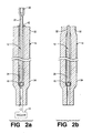
- Fig. 2a is a cross-sectional view of an overclad tube positioned around a preform core rod prior to collapsing the overclad tube around the preform core rod to make an overclad preform according to a conventional overclad during draw (ODD) process;
- Fig. 2b is a cross-sectional view of an overclad tube positioned around a preform core rod prior to collapsing the overclad tube around the preform core rod to make an overclad preform according to a conventional overclad during draw (ODD) process, showing the preform core rod sealed within overclad tube;
- Fig. 3a is a cross-sectional view of inner and outer overclad tubes positioned around a preform core rod prior to collapsing the overclad tubes around the preform core rod to make a multiple overclad preform according to embodiments of the invention;
- Fig. 3b is a cross-sectional view of inner and outer overclad tubes positioned around a preform core rod prior to collapsing the overclad tubes around the preform core rod to make a multiple overclad preform according to embodiments of the invention, showing the preform core rod and the overclad tubes sealed together; and
- Fig. 4 is a simplified block diagram of a method for making multiple overclad optical fiber preforms and making optical fiber therefrom.
-
- In the following description similar components are referred to by the same reference numeral in order to simplify the sequential aspect of the drawings and to enhance the understanding of the invention through the description of the drawings. Also, although specific features, configurations and arrangements are discussed hereinbelow, it should be understood that such is done for illustrative purposes only. A person skilled in the relevant art will recognize that other steps, configurations and arrangements are useful without departing from the spirit and scope of the invention.
- Referring now to Figs. 1a-b, illustrated is an apparatus 10 (Fig. 1a), comprising a
preform core rod 12 and an overcladtube 14, used to make an overclad preform 20 (Fig. 1b) according to a conventional Rod-In-Tube (RIT) process. In Fig. 1a, thepreform core rod 12 is positioned vertically within theoverclad tube 14 prior to the collapse of theoverclad tube 14 around thepreform core rod 12. Fig. 1b illustrates theoverclad preform 20 after theoverclad tube 14 has been collapsed around thepreform core rod 12. - The
preform core rod 12 is made by any suitable process, including conventional processes such as modified chemical vapor deposition (MCVD) or vapor axial deposition (VAD). Thepreform core rod 12 has aproximal end 22 and adistal end 24, and often is made with ahandle 26 at theproximal end 22. Thehandle 26 facilitates maneuvering thepreform core rod 12, for example, as thedistal end 24 of therod 12 is inserted into theoverclad tube 14. - The
overclad tube 14 has a first orproximal end 32 into which thepreform core rod 12 is inserted and a second ordistal end 34 configured for mounting into a chuck or other appropriate holding device. Anadjustable support rod 36 is positioned within thesecond end 34 of theoverclad tube 14 to provide support for thepreform core rod 12. - Once the
preform core rod 12 is positioned as desired within theoverclad tube 14, theproximal end 22 of thepreform core rod 12 is sealed off, for example, by aseal 42 or other appropriate means. A pressure gradient then is established across the region between thepreform core rod 12 and theoverclad tube 14, for example, by operably coupling avacuum source 44 to the distal end of theoverclad tube 14. Theoverclad tube 14 is heated while the pressure gradient is maintained across the region between thepreform core rod 12 and theoverclad tube 14, thus collapsing theoverclad tube 14 around thepreform core rod 12, for example, in accordance with a conventional Rod-In-Tube (RIT) process. The resultingoverclad preform 20 is shown in Fig. 1b. - As discussed previously herein, at least one more subsequent overcladding process is performed if the final size of the optical fiber is desired to be larger. That is, once the first overclad tube is collapsed onto the preform core rod using a first conventional RIT process, a second overclad tube is collapsed onto the existing
overclad preform 20 using a second conventional RIT process. The resulting double-clad or double overclad optical fiber preform is desirably larger than preforms made with a more conventional, single RIT overcladding process. For example, overclad optical fiber preforms that typically have an outer diameter, for example, of approximately 50 millimeters (mm), using a single RIT process are made to have an outer diameter, for example, of approximately 80 mm, using a second RIT process. - Also, as discussed previously herein, other variations of conventional RIT processes include collapsing the
overclad tube 14 on thepreform core rod 12 in the furnace of the draw tower used for drawing optical fiber from the resultingoverclad preform 20. Such process often is referred to as Overclad During Draw (ODD), and is shown generally in Figs. 2a-b and discussed briefly hereinbelow. - According to some ODD processes, the
preform core rod 12 is positioned, for example, vertically, within theoverclad tube 14. Aquartz disc 46 or other supporting or spacer means typically occupies the second ordistal end 34 of theoverclad tube 14. Theproximal end 22 of thepreform core rod 12 is sealed at the first orproximal end 32 of theoverclad tube 14, for example, by theseal 42 or other appropriate sealing means. - The
proximal end 22 of thepreform core rod 12 and theproximal end 32 of theoverclad tube 14 then are heated together to form a sealed, unitary structure. Fig. 2b shows one arrangement of the resultingoverclad tube 14 having thepreform core rod 12 sealingly positioned therein. - The combined
overclad tube 14 andpreform core rod 12 then is moved through a draw tower furnace (not shown), beginning with the sealed proximal ends 22, 32. In this manner, theoverclad tube 14 gradually but completely collapses onto thepreform core rod 12 prior to optical fiber being drawn from the resulting overclad preform. As discussed previously herein, the ODD process is advantageous, for example, in that separate heat treatment needed for collapsing the overclad tube on the preform outside of the furnace (for example, on a lathe) is not needed because the draw tower furnace provides such heat. Also not needed is some of the separate set-up and tube preparation processing associated with separate heat treatment steps. - Embodiments of the invention are based on the advantageous realization that the overcladding process times are improved and other efficiencies are gained by manufacturing dual, double or multiple overclad optical fiber preforms using an inventive overclad during draw (ODD) process. As will be discussed in greater detail hereinbelow, other advantages include improved overclad layer structure and more efficient use of overclad tube materials.
- Referring now to Figs. 3a-b, shown are an apparatus 50 (Fig. 3a) for making a dual overclad optical fiber preform according to embodiments of the invention and the resulting double overclad tube 60 (Fig. 3b) with the
preform core rod 12 sealingly positioned therein. Also, referring to Fig. 4, with continuing reference to Figs. 3a-b, shown is a simplified block diagram of amethod 70 for making dual overclad optical fiber preforms and for drawing optical fiber therefrom. - It should be understood that, although dual overclad embodiments are shown in Figs. 3-4 and described hereinbelow, embodiments of the invention include multiple overclad arrangements. Moreover, it is within the scope of alternative embodiments of the invention to modify the arrangement shown in Figs. 3a-b for multiple overclad arrangements and the method shown in Fig. 4 for multiple overclad manufacturing methods.
- The
inventive apparatus 50 shown in Fig. 3a includes apreform core rod 12, afirst overclad tube 14 and asecond overclad tube 56. Thepreform core rod 12 has aproximal end 22 with ahandle 26 and adistal end 24. Similarly, thefirst overclad tube 14 has aproximal end 32 and adistal end 34, and thesecond overclad tube 56 likewise has aproximal end 62 and adistal end 64. For multiple overclad embodiments of the invention, additional second overclad tubes are included. However, for purposes of discussion herein, only the first and second overclad tubes are shown in the Figs. - One
step 72 of themethod 70 is to position thepreform core rod 12 and thefirst overclad tube 14 within thesecond overclad tube 56, for example, by inserting the distal ends 24, 34 of thepreform core rod 12 and thefirst overclad tube 14, respectively, into theproximal end 62 of thesecond overclad tube 56. Thefirst overclad tube 14 typically will be shorter in length than thesecond overclad tube 56, although the final overall useful size of the preform does not differ disadvantageously from preforms made according to conventional techniques. - Another
step 74 of themethod 70 is to position thepreform core rod 12 within the overclad tubes, for example, by inserting thedistal end 24 of thepreform core rod 12 into theproximal end 32 of thefirst overclad tube 14. Thehandle 26 facilitates insertion of thepreform core rod 12 into thefirst overclad tube 14. Typically, thepreform core rod 12 and thefirst overclad tube 14 are dimensioned such that the outer diameter of thepreform core rod 12 is within the range from approximately 0.50 millimeters (mm) to approximately 1.75 mm from the inner diameter of thefirst overclad tube 14. Also, thepreform core rod 12 andfirst overclad tube 14 are configured in such a way that, when thepreform core rod 12 is positioned within thefirst overclad tube 14, the two are substantially coaxial with respect to one another. - A
support 46 such as a quartz disc or suitable spacer means supports both thepreform core rod 12 and thefirst overclad tube 14, as shown. Support for shorter preform core rods is achieved, for example, using one or more quartz spacers in addition to thequartz disc 46. Also, it is possible for thefirst overclad tube 14 to be configured such that thequartz disc 46 is positioned therein for supporting thepreform core rod 12 therein. Other supports including support rods are suitable for use in the inventive embodiments shown and described herein. - The
second overclad tube 56 is configured, for example, in such a way that thequartz disc 46 or other spacer means is positioned therein so as to supportably position thepreform core rod 12 and thefirst overclad tube 14 with respect to one another. For example, thedistal end 64 of thesecond overclad tube 56 is configured for mounting into a chuck or other appropriate holding device, and thus has a reduced inner diameter, which is dimensioned to position thequartz disc 46 therein. Also, the first and second overclad tubes are dimensioned such that the outer diameter of thefirst overclad tube 14 is within the range from approximately 0.50 mm to approximately 1.75 mm from the inner diameter of thesecond overclad tube 56. - Typically, the
preform core rod 12 and the overclad tubes are configured in such a way that, when positioned as shown, the three are substantially coaxial with respect to one another. A second seal orseal ring 58, or other suitable sealing means, is used to maintain the relative position of thefirst overclad tube 14 with respect to thesecond overclad tube 56, for example, by sealing theproximal end 32 of thefirst overclad tube 14 to theproximal end 62 of thesecond overclad tube 56. Thus, according to embodiments of the invention, the relative positions of thepreform core rod 12, thefirst overclad tube 14 and thesecond overclad tube 56 all are maintained with respect to one another and have been sealed off at their proximal ends. - The proximal ends of the
preform core rod 12, thefirst overclad tube 14 and thesecond overclad tube 56 then are heated or otherwise formed together in a manner that results in a sealed, unitary structure. The resulting structure is shown, for example, in Fig. 3b as anapparatus 60. - Another
step 76 in themethod 70 is to establish a pressure gradient across the sealed area, for example, using a vacuum source operably connected across the distal ends of thefirst overclad tube 14 and thesecond overclad tube 56. The established pressure gradient is such that the pressure outside thesecond overclad tube 56 is substantially greater than the pressure inside thesecond overclad tube 56, and the pressure outside thefirst overclad tube 14 is substantially greater than the pressure inside thefirst overclad tube 14. For example, the pressure gradient is within the range from approximately 0.25 to approximately 0.50 atmospheric pressure. - Another
step 78 in themethod 70 is to heat theapparatus 60 comprising thepreform core rod 12 and the overclad tubes, for example, within the range from approximately 1600-1700° C. According to an embodiment of the invention, theheating step 78 applies heat, for example, to successive axial portions of theapparatus 60, that is, along the length of theapparatus 60 from the proximal ends to the distal ends. Alternatively, theheating step 78 applies heat simultaneously to most if not all portions of the combined preform and dualoverclad tube apparatus 60. Such simultaneous heating generally is indicative of heating in conventional RIT processes. - The
heating step 78 causes the overclad tubes to collapse onto the preform core rod 12 (Fig. 3b generally illustrates theapparatus 60 prior to such collapsing). Thus, according to embodiments of the invention, a dual or multiple clad optical fiber preform is formed using a single rather than double RIT process. That is, one heating and collapsing step is used rather than conventional methods that typically require two separate heating and collapsing steps, that is, a first heating and collapsing step and then a subsequent, second heating and collapsing steps. - Moreover, according to alternative embodiments of the invention, the heat source used to heat and collapse the
dual overclad apparatus 60 is a draw tower furnace. That is, theinventive apparatus 60 is moved operably through a draw tower furnace, for example, as part of an overclad during draw (ODD) process. In this manner, the first andsecond overclad tubes preform core rod 12 using a single heat source and a single heating step. The resulting double-cladoptical fiber preform 60 then is used to draw optical fiber therefrom, for example, in a conventional manner. - Multiple overclad optical fiber preforms made according to embodiments of the invention include a number of advantageous features over conventionally made optical fiber preforms. For example, as mentioned briefly hereinabove, embodiments of the invention typically have relatively large preforms, which generally yield more optical fiber per preform than smaller preforms. Also, larger preforms reduce the overall number of preforms needed per unit of fiber length produced, which, in turn, reduces the overall amount of preform set-up and processing time.
- Moreover, embodiments of the invention significantly reduce set-up and processing time through the elimination of the steps of the first overcladding process. That is, whereas conventional processes require, for example, two or more separate overcladding processes, embodiments of the invention provide a dual or multiple overclad optical fiber preform using a single overcladding process. Thus, the set-up, heating, cooling and other associated process steps required for the additional overcladding, and the associated time thereof, are eliminated.
- Also, in addition to the advantages just discussed, preforms made according to embodiments of the invention manage to improve on existing benefits of conventional processes of making preforms. For example, compared to conventionally-made preforms, preforms made according to embodiments of the invention tend to have fewer interface breaks and tend to have less curl. Also, compared to conventionally-made preforms, preforms made according to embodiments of the invention tend to have better eccentricity, which refers to the consistency of the diameters of the preform core rod and the overclad tubes moving axially down the optical fiber preform.
- As shown in Fig. 4, the
method 70 includes thestep 79 of drawing optical fiber from the multiple overclad optical fiber preform. The drawingstep 79 is performed, for example, in a conventional manner. That is, the drawing step is performed once the inventive optical fiber preform has been manufactured. Alternatively, in an ODD-type process, the drawingstep 79 is performed as the overclad optical fiber preform is being formed, that is, as the overclad tubes are being collapsed onto thepreform core rod 12 within the draw tower furnace. - It will be apparent to those skilled in the art that many changes and substitutions can be made to the embodiments of the methods and apparatus for overcladding optical fiber preform rods herein described without departing from the spirit and scope of the invention as defined by the appended claims and their full scope of equivalents. For example, although embodiments of the invention typically apply a single ODD process to collapse both the first and second overclad tubes together, it should be understood that, alternatively, it is possible to use a conventional RIT process to collapse the first overclad tube and then use an ODD process to collapse the additional overclad tubes around the existing overclad preform rod. That is, the first overcladding is performed outside the fiber drawing heat source using conventional RIT techniques and then the additional overcladding is performed (at the fiber drawing furnace) using ODD techniques. In this manner, a multiple ODD process according to an alternative embodiment of the invention is performed.
Claims (10)
- A method of making a multiple overclad optical fiber preform, comprising the steps of:CHARACTERIZED IN THATproviding a preform core rod (12);positioning a first overclad tube (14) around the preform core rod; andheating the preform core and the overclad tube in such a way that the first overclad tube collapses onto the preform core to form an overclad optical fiber preform,the method further comprises positioning at least one second overclad tube (56) around the first overclad tube (14), andthe heating step further comprises heating the preform core and the overclad tubes in such a way that the first overclad tube collapses onto the preform core and the second overclad tubes collapse on the first overclad tube to form the multiple overclad optical fiber preform.
- The method as recited in claim 1, further comprising the step of creating a pressure gradient across the exterior of the second overclad tube and the interior of the first overclad tube.
- The method as recited in claim 1, wherein the first overclad tube has a proximal end and a distal end, wherein the second overclad tube has a proximal end and a distal end, and wherein the second overclad tube positioning step further comprises inserting the distal end of the first overclad tube into the proximal end of the second overclad tube.
- The method as recited in claim 1, wherein the preform core rod has a proximal end with a handle and a distal end, wherein the first overclad tube has a proximal end and a distal end, and wherein the first overclad tube positioning step further comprises inserting the distal end of the preform rod into the proximal end of the first overclad tube.
- The method as recited in claim 1, further comprising the step of drawing an optical fiber from the overclad optical fiber preform.
- The method as recited in claim 5, wherein the drawing step and the heating step are performed using the same heat source.
- The method as recited in claim 1, wherein the first overclad tube positioning step further comprises positioning the preform core rod within the first overclad tube in such a way that the first overclad tube and the preform core rod are in fixed relation with respect to one another.
- The method as recited in claim 1, wherein the first overclad tube positioning step further comprises positioning the preform core rod within the first overclad tube in such a way that the first overclad tube and the preform core rod are substantially coaxial.
- The method as recited in claim 1, wherein the second overclad tube positioning step further comprises positioning the first overclad tube within the second overclad tube in such a way that the first and second overclad tubes are substantially coaxial.
- A method of making an optical fiber, comprising the steps of:CHARACTERIZED IN THATproviding a preform core rod (12);positioning a first overclad tube (14) around the preform core rod;heating the preform core rod and the first overclad tube wherein the first overclad tube collapses onto the preform core rod to form an overclad optical fiber preform; anddrawing the optical fiber from the overclad optical fiber preform,the method further comprises positioning at least one second overclad tube (56) around the first overclad tube (14), and establishing a pressure gradient across the exterior and the interior of at least the second overclad tube, wherein the pressure outside the second overclad tube is greater than the pressure inside the second overclad tube, andthe heating step further comprises heating the preform core rod, the first overclad tube and the at least one second overclad tube wherein the first overclad tube collapses onto the preform core rod and the second overclad tube collapses on the first overclad tube to form a multiple overclad optical fiber preform.
Applications Claiming Priority (2)
| Application Number | Priority Date | Filing Date | Title |
|---|---|---|---|
| US515227 | 2000-02-29 | ||
| US09/515,227 US6460378B1 (en) | 2000-02-29 | 2000-02-29 | Collapsing a multitube assembly and subsequent optical fiber drawing in the same furnace |
Publications (2)
| Publication Number | Publication Date |
|---|---|
| EP1129999A2 true EP1129999A2 (en) | 2001-09-05 |
| EP1129999A3 EP1129999A3 (en) | 2001-11-21 |
Family
ID=24050471
Family Applications (1)
| Application Number | Title | Priority Date | Filing Date |
|---|---|---|---|
| EP01301433A Withdrawn EP1129999A3 (en) | 2000-02-29 | 2001-02-19 | Method for making multiple overclad optical fiber preforms |
Country Status (3)
| Country | Link |
|---|---|
| US (1) | US6460378B1 (en) |
| EP (1) | EP1129999A3 (en) |
| JP (1) | JP2001287920A (en) |
Cited By (18)
| Publication number | Priority date | Publication date | Assignee | Title |
|---|---|---|---|---|
| DE10214029A1 (en) * | 2002-03-22 | 2003-05-08 | Heraeus Tenevo Ag | Optical fiber production comprises elongating coaxial arrangement consisting of core rod and outer casing from quartz glass cylinder by feeding into heating zone, softening zones and drawing optical fibers from the softened region |
| WO2003080522A1 (en) * | 2002-03-22 | 2003-10-02 | Heraeus Tenevo Ag | Method for producing an optical fiber and optical fiber |
| FR2839714A1 (en) * | 2002-05-15 | 2003-11-21 | Fitel Usa Corp | Production of a preformer for a coated fibre optic by positioning a coated tube around the shaft of a preformed core and applying a rod-in-tube procedure with improved correspondence between them |
| US6701753B2 (en) | 2001-02-11 | 2004-03-09 | Fitel Usa Corp. | Method and apparatus for making improved optical fiber preforms and optical fiber therefrom |
| NL1021992C2 (en) * | 2002-11-26 | 2004-05-27 | Draka Fibre Technology Bv | Rod in tube process for preparing optical fibre preform, by heating rod and mantle separated by cavity containing deuterium |
| EP1426339A1 (en) * | 2002-12-04 | 2004-06-09 | FITEL USA CORPORATION (a Delaware Corporation) | Rod-in-tube optical fibre preform and method of drawing it |
| GB2397300A (en) * | 2003-01-06 | 2004-07-21 | Weatherford Lamb | Making a large diameter optical waveguide preform |
| WO2005009912A1 (en) * | 2003-07-18 | 2005-02-03 | Heraeus Tenevo Gmbh | Method for production of an optical component made from quartz glass and hollow cylinder made from quartz glass for carrying out said method |
| EP1598322A1 (en) * | 2004-05-15 | 2005-11-23 | Samsung Electronics Co., Ltd. | Method and apparatus for overcladding glass rod |
| DE102004054654A1 (en) * | 2004-11-11 | 2006-05-18 | Heraeus Tenevo Gmbh | Preparation of optical component from quartz glass by elongation of coaxial joint of hollow cylinder enables a core bar to be fixed reproducibly at small cost in a hollow cylinder inner bore |
| EP1712934A1 (en) * | 2005-03-23 | 2006-10-18 | Furukawa Electric North America Inc. | Optical fiber preform with overclad tubes |
| US7143611B2 (en) * | 2003-09-19 | 2006-12-05 | Fitel Usa Corp | Rod-In-Tube optical fiber preform assembly and method having reduced movement |
| WO2007009450A1 (en) * | 2005-07-20 | 2007-01-25 | J-Fiber Gmbh | Method for producing glass-fibre preforms with a large core diameter |
| US8015846B2 (en) | 2004-08-14 | 2011-09-13 | Heraeus Quarzglas Gmbh & Co. Kg | Elongation method for producing an optical component of quartz glass and preliminary product suited for performing the method |
| CN102249534A (en) * | 2011-05-31 | 2011-11-23 | 长飞光纤光缆有限公司 | Full diameter optical fiber preform rod induction fiber drawing furnace heating apparatus |
| US8161772B2 (en) * | 2004-06-11 | 2012-04-24 | Heraeus Quarzglas Gmbh & Co. Kg | Method for the production of an optical component made from quartz glass |
| CN107082558A (en) * | 2017-04-27 | 2017-08-22 | 烽火通信科技股份有限公司 | Method for manufacturing the preform of single-mode fiber and manufacturing single-mode fiber |
| CN107098578A (en) * | 2017-04-27 | 2017-08-29 | 烽火通信科技股份有限公司 | Method for manufacturing the preform of sandwich construction optical fiber and manufacturing optical fiber |
Families Citing this family (20)
| Publication number | Priority date | Publication date | Assignee | Title |
|---|---|---|---|---|
| KR100342476B1 (en) * | 1999-12-10 | 2002-06-28 | 윤종용 | High effective over-cladding burner and large diameter optical fiber preform over-cladding apparatus using the same |
| KR100496448B1 (en) * | 2002-06-15 | 2005-06-20 | 엘에스전선 주식회사 | method of prevention of water generation in the jacketing tube during RIT and apparatus thereof |
| US6810691B2 (en) * | 2002-06-28 | 2004-11-02 | Corning Incorporated | Method for making glass tubing with multiple bores |
| US20040221617A1 (en) * | 2003-05-05 | 2004-11-11 | Fleming James William | Methods for modifying ovality of optical fiber preforms |
| DE102004014345B4 (en) * | 2004-03-22 | 2007-09-20 | Heraeus Tenevo Gmbh | Method for producing an optical component |
| US8789393B2 (en) * | 2004-11-29 | 2014-07-29 | The Furukawa Electric Co., Ltd. | Optical fiber preform, method of manufacturing optical fiber preform, and method of manufacturing optical fiber |
| CN100395203C (en) * | 2005-08-17 | 2008-06-18 | 长飞光纤光缆有限公司 | Method for preparing preformod of optical fiber with low water peak in large size |
| US20070284097A1 (en) | 2006-06-08 | 2007-12-13 | Halliburton Energy Services, Inc. | Consumable downhole tools |
| US20080257549A1 (en) | 2006-06-08 | 2008-10-23 | Halliburton Energy Services, Inc. | Consumable Downhole Tools |
| US20080202764A1 (en) | 2007-02-22 | 2008-08-28 | Halliburton Energy Services, Inc. | Consumable downhole tools |
| US7836728B2 (en) * | 2007-05-09 | 2010-11-23 | Ofs Fitel, Llc | Increasing the cladding-to-core ratio (D/d) of low D/d ratio core rods in optical fiber performs |
| US8327926B2 (en) | 2008-03-26 | 2012-12-11 | Robertson Intellectual Properties, LLC | Method for removing a consumable downhole tool |
| US8235102B1 (en) | 2008-03-26 | 2012-08-07 | Robertson Intellectual Properties, LLC | Consumable downhole tool |
| US20140186645A1 (en) * | 2013-01-02 | 2014-07-03 | Ofs Fitel, Llc | Manufacture of bend insensitive multimode optical fiber |
| JP5921518B2 (en) | 2013-11-18 | 2016-05-24 | 株式会社フジクラ | Multi-core fiber and method for producing the multi-core fiber |
| JP6447279B2 (en) * | 2015-03-18 | 2019-01-09 | 住友電気工業株式会社 | Optical fiber manufacturing method |
| KR102335065B1 (en) * | 2015-06-02 | 2021-12-06 | 헤래우스 쿼츠 노쓰 아메리카 엘엘씨 | Method for inserting a core rod into an outer cladding tube with a spacer |
| NL2015161B1 (en) * | 2015-07-13 | 2017-02-01 | Draka Comteq Bv | A method for preparing a primary preform by etching and collapsing a deposited tube. |
| JP7068945B2 (en) * | 2017-08-09 | 2022-05-17 | 株式会社フジクラ | Manufacturing method of optical fiber base material, manufacturing method of optical fiber base material, optical fiber |
| CN114409242B (en) * | 2021-12-01 | 2023-08-18 | 浙江富通光纤技术有限公司 | Process for manufacturing optical fiber preform and optical fiber |
Citations (3)
| Publication number | Priority date | Publication date | Assignee | Title |
|---|---|---|---|---|
| US4820322A (en) * | 1986-04-28 | 1989-04-11 | American Telephone And Telegraph Company At&T Bell Laboratories | Method of and apparatus for overcladding a glass rod |
| DE4005729A1 (en) * | 1990-02-23 | 1991-08-29 | Kabelmetal Electro Gmbh | Optical waveguide mfr. - by using glass tubes over rod blank with evacuation of hollow spaces between them |
| EP0698582A2 (en) * | 1994-08-26 | 1996-02-28 | Sumitomo Electric Industries, Ltd. | Method of fabricating dispersion compensation fiber |
Family Cites Families (15)
| Publication number | Priority date | Publication date | Assignee | Title |
|---|---|---|---|---|
| US4217027A (en) | 1974-02-22 | 1980-08-12 | Bell Telephone Laboratories, Incorporated | Optical fiber fabrication and resulting product |
| JPS5181143A (en) | 1975-01-11 | 1976-07-15 | Sumitomo Electric Industries | HIKARIDENSOYOFUAIBANOSEIZOHOHO |
| IT1119362B (en) * | 1979-09-10 | 1986-03-10 | Cselt Centro Studi Lab Telecom | PROCEDURE AND EQUIPMENT FOR THE PRODUCTION OF PREFORMS FOR OPTICAL FIBERS |
| CA1136911A (en) * | 1979-10-25 | 1982-12-07 | Takao Edahiro | Optical transmission fiber and process for producing the same |
| JPS5792536A (en) * | 1980-11-29 | 1982-06-09 | Dainichi Nippon Cables Ltd | Preparation of parent material of optical glass fiber |
| US4596589A (en) * | 1984-02-09 | 1986-06-24 | Perry Gregory A | Method for producing a single mode fiber preform |
| US4547644A (en) | 1984-02-24 | 1985-10-15 | At&T Technologies, Inc. | Apparatus for heating a preform from which lightguide fiber is drawn |
| JPS61132535A (en) * | 1984-11-28 | 1986-06-20 | Furukawa Electric Co Ltd:The | Production of quartz-based optical fiber |
| US4882209A (en) * | 1986-09-11 | 1989-11-21 | Asahi Glass Company, Ltd. | Glass capillary tube and method for its production |
| JPS63147837A (en) * | 1986-12-11 | 1988-06-20 | Seiko Epson Corp | Production of glass body for optical transmission |
| US4775401A (en) | 1987-06-18 | 1988-10-04 | American Telephone And Telegraph Company, At&T Bell Laboratories | Method of producing an optical fiber |
| GB2208114A (en) * | 1987-07-01 | 1989-03-01 | Pirelli General Plc | Optical fibre preforms |
| JPH0196038A (en) * | 1987-10-08 | 1989-04-14 | Seiko Epson Corp | Production of distributed refractive index lens |
| DE4028275A1 (en) * | 1990-09-06 | 1992-03-12 | Kabelmetal Electro Gmbh | METHOD FOR THE PRODUCTION OF FIBERGLASS FIBER OPTICS WITH INCREASED STRENGTH |
| KR0162604B1 (en) * | 1994-10-07 | 1999-04-15 | 김광호 | Optical fiber preform making method |
-
2000
- 2000-02-29 US US09/515,227 patent/US6460378B1/en not_active Expired - Lifetime
-
2001
- 2001-02-19 EP EP01301433A patent/EP1129999A3/en not_active Withdrawn
- 2001-02-28 JP JP2001053269A patent/JP2001287920A/en active Pending
Patent Citations (3)
| Publication number | Priority date | Publication date | Assignee | Title |
|---|---|---|---|---|
| US4820322A (en) * | 1986-04-28 | 1989-04-11 | American Telephone And Telegraph Company At&T Bell Laboratories | Method of and apparatus for overcladding a glass rod |
| DE4005729A1 (en) * | 1990-02-23 | 1991-08-29 | Kabelmetal Electro Gmbh | Optical waveguide mfr. - by using glass tubes over rod blank with evacuation of hollow spaces between them |
| EP0698582A2 (en) * | 1994-08-26 | 1996-02-28 | Sumitomo Electric Industries, Ltd. | Method of fabricating dispersion compensation fiber |
Non-Patent Citations (5)
| Title |
|---|
| DATABASE WPI Section Ch, Week 197635 Derwent Publications Ltd., London, GB; Class F01, AN 1976-65845x XP002178363 -& JP 51 081143 A (SUMITOMO ELECTRIC IND CO LTD), 15 July 1976 (1976-07-15) * |
| PATENT ABSTRACTS OF JAPAN vol. 10, no. 321, 31 October 1986 (1986-10-31) & JP 61 132535 A (FURUKAWA ELECTRIC CO LTD), 20 June 1986 (1986-06-20) * |
| PATENT ABSTRACTS OF JAPAN vol. 12, no. 410, 28 October 1988 (1988-10-28) & JP 63 147837 A (SEIKO EPSON CORP), 20 June 1988 (1988-06-20) * |
| PATENT ABSTRACTS OF JAPAN vol. 13, no. 308, 14 July 1989 (1989-07-14) & JP 01 096038 A (SEIKO EPSON CORP), 14 April 1989 (1989-04-14) * |
| PATENT ABSTRACTS OF JAPAN vol. 6, no. 177, 11 September 1982 (1982-09-11) & JP 57 092536 A (DAINICHI NIPPON CABLES CO LTD), 9 June 1982 (1982-06-09) * |
Cited By (32)
| Publication number | Priority date | Publication date | Assignee | Title |
|---|---|---|---|---|
| US6701753B2 (en) | 2001-02-11 | 2004-03-09 | Fitel Usa Corp. | Method and apparatus for making improved optical fiber preforms and optical fiber therefrom |
| US7028508B2 (en) | 2002-03-22 | 2006-04-18 | Heraeus Tenevo Gmbh | Method for producing an optical fiber and optical fiber |
| DE10214029A1 (en) * | 2002-03-22 | 2003-05-08 | Heraeus Tenevo Ag | Optical fiber production comprises elongating coaxial arrangement consisting of core rod and outer casing from quartz glass cylinder by feeding into heating zone, softening zones and drawing optical fibers from the softened region |
| DE10214029C2 (en) * | 2002-03-22 | 2003-09-18 | Heraeus Tenevo Ag | Method for producing an optical fiber and optical fiber produced by the method |
| WO2003080522A1 (en) * | 2002-03-22 | 2003-10-02 | Heraeus Tenevo Ag | Method for producing an optical fiber and optical fiber |
| FR2839714A1 (en) * | 2002-05-15 | 2003-11-21 | Fitel Usa Corp | Production of a preformer for a coated fibre optic by positioning a coated tube around the shaft of a preformed core and applying a rod-in-tube procedure with improved correspondence between them |
| NL1021992C2 (en) * | 2002-11-26 | 2004-05-27 | Draka Fibre Technology Bv | Rod in tube process for preparing optical fibre preform, by heating rod and mantle separated by cavity containing deuterium |
| EP1426339A1 (en) * | 2002-12-04 | 2004-06-09 | FITEL USA CORPORATION (a Delaware Corporation) | Rod-in-tube optical fibre preform and method of drawing it |
| CN100497224C (en) * | 2002-12-04 | 2009-06-10 | 菲特尔美国公司 | Rod-in-tube optical fiber preform and method |
| GB2397300A (en) * | 2003-01-06 | 2004-07-21 | Weatherford Lamb | Making a large diameter optical waveguide preform |
| GB2397300B (en) * | 2003-01-06 | 2006-05-17 | Weatherford Lamb | Method of fusing and stretching a large diameter optical waveguide |
| US7854146B2 (en) | 2003-07-18 | 2010-12-21 | Heraeus Quarzglas Gmbh & Co. Kg | Method for production of an optical component from quartz glass |
| DE10333059A1 (en) * | 2003-07-18 | 2005-02-17 | Heraeus Tenevo Ag | Method for producing an optical component made of quartz glass and hollow cylinder made of quartz glass for carrying out the method |
| WO2005009912A1 (en) * | 2003-07-18 | 2005-02-03 | Heraeus Tenevo Gmbh | Method for production of an optical component made from quartz glass and hollow cylinder made from quartz glass for carrying out said method |
| DE112004001053B4 (en) * | 2003-07-18 | 2007-07-19 | Heraeus Tenevo Gmbh | Method for producing an optical component made of quartz glass |
| US7681416B2 (en) | 2003-07-18 | 2010-03-23 | Heraeus Quarzglas Gmbh & Co. Kg | Method for production of an optical component made from quartz glass |
| WO2005009913A1 (en) * | 2003-07-18 | 2005-02-03 | Heraeus Tenevo Gmbh | Method for production of an optical component from quartz glass |
| DE112004001055B4 (en) * | 2003-07-18 | 2007-12-20 | Heraeus Tenevo Gmbh | Method for producing an optical component made of quartz glass and hollow cylinder made of quartz glass for carrying out the method |
| US7143611B2 (en) * | 2003-09-19 | 2006-12-05 | Fitel Usa Corp | Rod-In-Tube optical fiber preform assembly and method having reduced movement |
| EP1598322A1 (en) * | 2004-05-15 | 2005-11-23 | Samsung Electronics Co., Ltd. | Method and apparatus for overcladding glass rod |
| US8161772B2 (en) * | 2004-06-11 | 2012-04-24 | Heraeus Quarzglas Gmbh & Co. Kg | Method for the production of an optical component made from quartz glass |
| US8015846B2 (en) | 2004-08-14 | 2011-09-13 | Heraeus Quarzglas Gmbh & Co. Kg | Elongation method for producing an optical component of quartz glass and preliminary product suited for performing the method |
| DE102004054654A1 (en) * | 2004-11-11 | 2006-05-18 | Heraeus Tenevo Gmbh | Preparation of optical component from quartz glass by elongation of coaxial joint of hollow cylinder enables a core bar to be fixed reproducibly at small cost in a hollow cylinder inner bore |
| DE102004054654B4 (en) * | 2004-11-11 | 2007-08-02 | Heraeus Tenevo Gmbh | Method for producing an optical component made of quartz glass |
| EP1712934A1 (en) * | 2005-03-23 | 2006-10-18 | Furukawa Electric North America Inc. | Optical fiber preform with overclad tubes |
| WO2007009450A1 (en) * | 2005-07-20 | 2007-01-25 | J-Fiber Gmbh | Method for producing glass-fibre preforms with a large core diameter |
| CN102249534A (en) * | 2011-05-31 | 2011-11-23 | 长飞光纤光缆有限公司 | Full diameter optical fiber preform rod induction fiber drawing furnace heating apparatus |
| US8950218B2 (en) | 2011-05-31 | 2015-02-10 | Yangze Optical Fibre And Cable Company Ltd. | Heating apparatus of induction furnace used for stretching large-diameter preformed rods of optical fibers |
| CN107082558A (en) * | 2017-04-27 | 2017-08-22 | 烽火通信科技股份有限公司 | Method for manufacturing the preform of single-mode fiber and manufacturing single-mode fiber |
| CN107098578A (en) * | 2017-04-27 | 2017-08-29 | 烽火通信科技股份有限公司 | Method for manufacturing the preform of sandwich construction optical fiber and manufacturing optical fiber |
| CN107098578B (en) * | 2017-04-27 | 2019-06-25 | 烽火通信科技股份有限公司 | Method for manufacturing the preform of multilayered structure optical fiber and manufacturing optical fiber |
| CN107082558B (en) * | 2017-04-27 | 2019-12-03 | 烽火通信科技股份有限公司 | A method of single mode optical fiber is manufactured using preform |
Also Published As
| Publication number | Publication date |
|---|---|
| JP2001287920A (en) | 2001-10-16 |
| US6460378B1 (en) | 2002-10-08 |
| EP1129999A3 (en) | 2001-11-21 |
Similar Documents
| Publication | Publication Date | Title |
|---|---|---|
| US6460378B1 (en) | Collapsing a multitube assembly and subsequent optical fiber drawing in the same furnace | |
| US8132429B2 (en) | Method for fabricating an optical fiber, preform for fabricating an optical fiber, optical fiber and apparatus | |
| EP0656325B1 (en) | Method for making optical fiber preforms | |
| US6584808B1 (en) | Method of manufacturing an optical fiber preform by collapsing a tube onto a rod | |
| US6883351B2 (en) | Method for fabricating a low polarization mode dispersion optical fiber | |
| US20040050110A1 (en) | Methods for fabricating optical fibers and optical fiber preforms | |
| US8196437B2 (en) | Increasing the cladding-to-core ratio (D/d) of low D/d core rods in optical fiber preforms | |
| US20020108403A1 (en) | Method and apparatus for making improved optical fiber preforms and optical fiber therefrom | |
| CN109942182B (en) | Optical fiber preform manufacturing method based on sleeve method | |
| EP1182173A1 (en) | Preform for optical fibres and methods for making the preform and optical fibres | |
| US6446468B1 (en) | Process for fabricating optical fiber involving overcladding during sintering | |
| US20040123630A1 (en) | Preform fabrication process | |
| US20090260400A1 (en) | Method for Producing a Tubular Semifinished Product From Fluorine-Doped Quartz Glass | |
| US5429653A (en) | Method of partially introverting a multiple layer tube to form an optical fiber preform | |
| US20020178761A1 (en) | Method of low PMD optical fiber manufacture | |
| JPS5992940A (en) | Production of optical fiber having pore | |
| US8464557B2 (en) | Method of producing optical fiber preform and optical fiber | |
| US20040099013A1 (en) | Optical fibers and methods of fabrication | |
| WO2002008133A2 (en) | Process of manufacturing glass optical fibre preforms | |
| JP3838850B2 (en) | Manufacturing method for optical fiber preform | |
| JPH0930823A (en) | Optical fiber preform, optical fiber and its production | |
| CN115784599A (en) | Low-crosstalk image transmission optical fiber and preparation method thereof | |
| EP1544173A1 (en) | Glass preform for an optical fibre and method and apparatus for its manufacture | |
| JPS63170235A (en) | Production of base material for drawing optical fiber | |
| JP2003165733A (en) | Method for producing glass tube and method for producing base material for optical fiber glass |
Legal Events
| Date | Code | Title | Description |
|---|---|---|---|
| PUAI | Public reference made under article 153(3) epc to a published international application that has entered the european phase |
Free format text: ORIGINAL CODE: 0009012 |
|
| AK | Designated contracting states |
Kind code of ref document: A2 Designated state(s): DE FR GB Kind code of ref document: A2 Designated state(s): AT BE CH CY DE DK ES FI FR GB GR IE IT LI LU MC NL PT SE TR |
|
| AX | Request for extension of the european patent |
Free format text: AL;LT;LV;MK;RO;SI |
|
| PUAL | Search report despatched |
Free format text: ORIGINAL CODE: 0009013 |
|
| AK | Designated contracting states |
Kind code of ref document: A3 Designated state(s): AT BE CH CY DE DK ES FI FR GB GR IE IT LI LU MC NL PT SE TR |
|
| AX | Request for extension of the european patent |
Free format text: AL;LT;LV;MK;RO;SI |
|
| AKX | Designation fees paid | ||
| 17P | Request for examination filed |
Effective date: 20020409 |
|
| RBV | Designated contracting states (corrected) |
Designated state(s): DE FR GB |
|
| REG | Reference to a national code |
Ref country code: DE Ref legal event code: 8566 |
|
| 17Q | First examination report despatched |
Effective date: 20050329 |
|
| STAA | Information on the status of an ep patent application or granted ep patent |
Free format text: STATUS: THE APPLICATION HAS BEEN WITHDRAWN |
|
| 18W | Application withdrawn |
Effective date: 20051209 |