EP1712934A1 - Optical fiber preform with overclad tubes - Google Patents
Optical fiber preform with overclad tubes Download PDFInfo
- Publication number
- EP1712934A1 EP1712934A1 EP05015251A EP05015251A EP1712934A1 EP 1712934 A1 EP1712934 A1 EP 1712934A1 EP 05015251 A EP05015251 A EP 05015251A EP 05015251 A EP05015251 A EP 05015251A EP 1712934 A1 EP1712934 A1 EP 1712934A1
- Authority
- EP
- European Patent Office
- Prior art keywords
- tube
- overclad
- overclad tube
- core rod
- preform
- Prior art date
- Legal status (The legal status is an assumption and is not a legal conclusion. Google has not performed a legal analysis and makes no representation as to the accuracy of the status listed.)
- Ceased
Links
Images


Classifications
-
- G—PHYSICS
- G02—OPTICS
- G02B—OPTICAL ELEMENTS, SYSTEMS OR APPARATUS
- G02B6/00—Light guides; Structural details of arrangements comprising light guides and other optical elements, e.g. couplings
-
- C—CHEMISTRY; METALLURGY
- C03—GLASS; MINERAL OR SLAG WOOL
- C03B—MANUFACTURE, SHAPING, OR SUPPLEMENTARY PROCESSES
- C03B37/00—Manufacture or treatment of flakes, fibres, or filaments from softened glass, minerals, or slags
- C03B37/01—Manufacture of glass fibres or filaments
- C03B37/012—Manufacture of preforms for drawing fibres or filaments
- C03B37/01205—Manufacture of preforms for drawing fibres or filaments starting from tubes, rods, fibres or filaments
- C03B37/01211—Manufacture of preforms for drawing fibres or filaments starting from tubes, rods, fibres or filaments by inserting one or more rods or tubes into a tube
-
- G—PHYSICS
- G02—OPTICS
- G02B—OPTICAL ELEMENTS, SYSTEMS OR APPARATUS
- G02B6/00—Light guides; Structural details of arrangements comprising light guides and other optical elements, e.g. couplings
- G02B6/02—Optical fibres with cladding with or without a coating
-
- C—CHEMISTRY; METALLURGY
- C03—GLASS; MINERAL OR SLAG WOOL
- C03B—MANUFACTURE, SHAPING, OR SUPPLEMENTARY PROCESSES
- C03B2201/00—Type of glass produced
- C03B2201/02—Pure silica glass, e.g. pure fused quartz
- C03B2201/03—Impurity concentration specified
-
- C—CHEMISTRY; METALLURGY
- C03—GLASS; MINERAL OR SLAG WOOL
- C03B—MANUFACTURE, SHAPING, OR SUPPLEMENTARY PROCESSES
- C03B2201/00—Type of glass produced
- C03B2201/02—Pure silica glass, e.g. pure fused quartz
- C03B2201/03—Impurity concentration specified
- C03B2201/04—Hydroxyl ion (OH)
-
- Y—GENERAL TAGGING OF NEW TECHNOLOGICAL DEVELOPMENTS; GENERAL TAGGING OF CROSS-SECTIONAL TECHNOLOGIES SPANNING OVER SEVERAL SECTIONS OF THE IPC; TECHNICAL SUBJECTS COVERED BY FORMER USPC CROSS-REFERENCE ART COLLECTIONS [XRACs] AND DIGESTS
- Y10—TECHNICAL SUBJECTS COVERED BY FORMER USPC
- Y10T—TECHNICAL SUBJECTS COVERED BY FORMER US CLASSIFICATION
- Y10T428/00—Stock material or miscellaneous articles
- Y10T428/29—Coated or structually defined flake, particle, cell, strand, strand portion, rod, filament, macroscopic fiber or mass thereof
- Y10T428/2913—Rod, strand, filament or fiber
Definitions
- This invention relates to optical fiber preforms, and particularly to preforms that are prepared with multiple overclad tubes.
- Optical fibers for data and information transmission are typically produced by lowering one end of a glass fiber preform into the mouth of a vertical fiber draw furnace, and heating the preform as it descends through a hot zone inside the furnace. A drop of soft glass forms at the heated end of the preform, and an optical fiber is drawn from the soft drop.
- the preform may be assembled using a so-called rod-in-tube (RIT) technique.
- a solid glass rod is supported axially inside a cylindrical glass overclad tube.
- the rod may be comprised only of core material, or possess a circumferential outer layer of cladding material.
- the overclad tube thus acts as a source of outer cladding on fibers that are drawn from the assembled rod and tube.
- the glass rod is referred to hereafter simply as a "core" rod, even though the rod typically possesses an outer layer of cladding material.
- a core rod is placed inside a first overclad tube, and a second overclad tube is arranged over the first overclad tube.
- the core rod and the two overclad tubes are heated under such conditions as to cause a partial collapse of the tubes at one end of the rod, thus forming a unitary multiple overclad preform.
- the one end of the preform is later set up for insertion into a vertical fiber draw furnace.
- An ODD fiber having a desired cladding to core mass ratio is then drawn inside the furnace as the tubes collapse further and consolidate with the core rod.
- the use of larger preform sizes both in length and diameter, can yield cost benefits.
- the effective length of the core rod determines the useful length of the preform. But manufacturing long rods of core material, e.g., more than two meters in length, is difficult due to defects such as the formation of bubbles or deviations in optical properties beyond specified limits. Typically, only relatively short remnants will remain after defective portions of a single long core rod are cut away.
- the interface between the outer circumference of the core rod and the inner circumference of the first overclad tube is critical, and must meet stringent material property requirements.
- concentration of hydroxyl (OH) ions or "water” greatly affects signal attenuation through so-called zero or low water peak (1383 nm) optical fiber.
- an overclad optical fiber preform includes a first glass overclad tube having a tube axis, and a number of core rod segments arranged axially end to end inside the first overclad tube.
- the tube has a first concentration of a given impurity at an interface with the core rod segments, the impurity contributing to signal attenuation in a fiber to be drawn from the preform.
- a second glass overclad tube is disposed coaxially about the first overclad tube, and has a second concentration of the given impurity which is larger than the first concentration of the impurity.
- a method of assembling an optical fiber preform includes inserting a plurality of core rod segments axially end to end inside a first glass overclad tube having an axis, and a first concentration of a given impurity at an interface with the core rod segments, the impurity contributing to signal attenuation in a fiber to be drawn from the preform.
- the first overclad tube and the core rod segments are inserted inside a second glass overclad tube having a second concentration of the given impurity which is larger than the first concentration of the impurity.
- FIG. 1 shows an optical fiber preform 10 according to the invention.
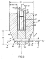
- FIG. 2 is an enlarged cross section of a lower portion of the preform 10 in FIG. 1.
- the preform 10 includes a number of cylindrical core rod segments 18 that are stacked axially end to end inside a first glass overclad tube 20.
- the rod segments 18 may originate from a single long cladded core rod produced by a known modified chemical vapor deposition (MCVD) process, or by an equivalent process such as, without limitation, vapor axial deposition (VAD) or outside vapor deposition (OVD).
- MCVD modified chemical vapor deposition
- VAD vapor axial deposition
- OTD outside vapor deposition
- each of the rod segments 18 may comprise uncladded fiber core material only.
- the axial end faces of the segments 18 are preferably cut flat using, e.g., a diamond saw.
- the first overclad tube 20 is aligned axially inside of a second overclad tube 21.
- the second overclad tube 21 may be obtained in the form of a commercially available silica glass cylinder.
- the circumference of a distal or lower end 16 of the tube 21 as viewed in the drawing is preferably formed to a frustoconical shape with a radially inward taper T (FIG. 2) of, e.g., approximately 24 degrees.
- a hollow cylindrical handle 23 (see FIG. 1) is formed at the top of the tube 21, and a short glass spacer 25 is seated at the bottom of an axial bore 27 in the handle 23.
- the spacer 25 is inserted axially from the bottom end of the second overclad tube 21, to a position where the spacer is blocked from further movement into the bore 27 of the tube handle 23 by, e.g., an annular protrusion or radial step 31 formed at the bottom of the handle bore 27.
- the spacer 25 therefore also serves to stop the first overclad tube 20 from movement into the handle bore 27.
- the glass forming the second overclad tube 21 may contain a higher concentration of a given impurity than the concentration of the same impurity in the first overclad tube 20, without causing any significant increase in signal attenuation through a fiber drawn from the assembled preform 10.
- the ambient surroundings introduce approximately 2 parts per million (ppm) of OH at the interface between the outer circumference of a core rod and the inner circumference of a first overclad tube.
- This OH concentration, together with residual OH present in the core rod and typical Rayleigh scattering losses, can be shown to account for about 0.28 dB of attenuation per kilometer (km) of the drawn fiber at a wavelength of 1383 nm.
- the OH adds about 0.002 dB/km attenuation.
- the second overclad tube is formed from glass having an OH concentration as high as 5.0 ppm, only about 0.00015 dB/km of fiber attenuation has been found to be attributable to the OH in the second overclad tube.
- the first overclad tube 20 is preferably formed of high quality glass, but with a relatively thin tube wall (e.g., between about 4 and 6 mm) so as to minimize costs.
- the second overclad tube 21 may have a substantially greater wall thickness (e.g., about 28 mm) to achieve a desired cladding to core mass ratio for the drawn fiber, and yet be formed from glass costing appreciably less than the glass of the first overclad tube 20.
- FIG. 3 shows the lower portion of the preform 10 as seen when rotated 90 degrees about its long axis A with respect to the view in FIG. 2.
- the lower end 16 of the entire fiber preform 10 can be positioned as a stable mechanical assembly for insertion into a mouth 12 of a vertical fiber draw furnace 14 at the beginning of a fiber draw process.
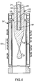
- the taper angle T approximates a neck down inclination 13, shown in FIG. 4, which is assumed by the lower end of the preform 10 when the end softens in a hot zone 15 of the fiber draw furnace 14, thus forming a soft glass drop 17.
- a proper choice for the taper angle T can maximize the usable axial length of the preform 10 for fiber draw, and may also minimize the size of the drop 17 so as to facilitate the initiation of fiber draw from the preform.
- a cylindrical plug 22 is supported inside the open distal end of the second glass overclad tube 21 as shown in FIGS. 1 to 3.
- the plug 22 is formed, e.g., from commercially available natural or synthetic fused silica, or equivalent material. Openings 24, 26 (FIG. 2) are drilled or otherwise formed through the conically shaped wall of the tube 21 at diametrically opposed locations at the lower end of the tube, and along an axis O perpendicular to the tube axis A.
- the plug 22 is fixed with respect to the tube 21 by a pin 28 which is inserted through one of the openings 24, 26, and passes through a transverse bore 30 in the plug to engage the opposite one of the openings 26, 24 in the tube wall.
- the pin 28 is formed from, e.g., commercially available synthetic fused silica or equivalent material.
- the spacer 25 is inserted axially through the lower or distal end of the second overclad tube 21, followed by the first overclad tube 20 including the core rod segments 18, and then the plug 22.
- the spacer 25, core rod segments 18 and plug 22 are initially loaded axially into an elongated tubular holder, wherein plastics balls or spacers are disposed (a) between confronting axial end faces of the segments, (b) between the spacer 25 and an uppermost rod segment, and (c) between the plug 22 and a lowermost rod segment.
- This procedure allows the spacer 25, the core rod segments 18, and the plug 22 to be washed clean by flowing, e.g., HF acid between open front and rear axial ends of the tubular holder followed by a rinse using deionized water.
- the plastics spacers act as a cushion between the glass parts 25, 18, 22, and thus prevent the parts from scratching during the cleaning process.
- the spacer 25 may be displaced from the front end of the holder and inserted in the open distal end of the second overclad tube 21.
- the first overclad tube 20 is then aligned with the holder, and the core rod segments 18 are urged successively into the tube 20 by, for example, a push rod inserted through the rear end of the holder in such a manner that the plastics spacers are allowed to fall away or are otherwise removed as successive ones of the segments 18 are inserted axially end to end inside the first overclad tube 20.
- the tube 20 is inserted axially into the second overclad tube 21 until the proximal or top end of the tube 20 confronts the spacer 25 and urges the spacer toward the protrusion 31 in the handle bore 27.
- the plug 22 is then placed in the distal end of the tube 21 so that opposite ends of the plug bore 30 register with the openings 24, 26 in the tapered tube wall, and the pin 28 is inserted through the plug bore and the wall openings to fix the plug at the distal end of the tube 21.
- the rod segments 18 and the first overclad tube 20 are dimensioned so that a radial clearance gap G1 of, for example, approximately 1 mm +/- 0.5 mm exists between the inner periphery of the tube 20 and the outer periphery of the inserted rod segments 18. Depending on the circumstances, a larger gap may be deployed.
- the assembled optical fiber preform 10 When the assembled optical fiber preform 10 is vertically oriented as shown in FIG. 3 for set up prior to entering the furnace 14, a lowermost rod segment 18 is blocked by the plug 22 from dropping out of the open bottom end 32 (see FIG. 2) of the tube 20.
- the lower end of the preform 10 After passing through the mouth 12 of the draw furnace and descending through the furnace hot zone 15 as shown in FIG. 4, the lower end of the preform 10 is heated to a temperature (typically at least 2100 degrees C.) at which glass softens, and the plug 22 and the pin 28 in FIG. 3 melt and fuse with one another.
- the lowermost core rod segment 18 and a portion of the first overclad tube 20 also soften above the plug 22.
- the overclad tube 21 then collapses onto the tube 20, and the tube 20 collapses onto the softened rod segment to produce the drop 17.
- the collapsing steps may be assisted by communicating a partial vacuum of, for example, about -26 inches H g to the clearance gap G1 between the rod segments 18 and the first overclad tube 20 at an upper end of the preform 10, in a manner typically employed when carrying out conventional RIT processes.
- the vacuum is also preferably communicated to another radial gap G2 formed between the first and the second tubes 20, 21, by way of, e.g., grooves or passages formed in the spacer 25. See FIGS. 6 and 7.
- the preform 10 may be assembled with relative ease and without the need for a separate heating step to join parts of the preform to one another prior to fiber draw. By eliminating such prior step(s), manufacturing costs are significantly reduced and the yield obtained from the preform 10 increases. Moreover, various preform sizes and fiber types (e.g., single or multi-mode) can be realized by the present invention.
- the preform 10 may be placed in a furnace and heated only until the first and the second overclad tubes 20, 21 collapse about the core rod segments 18. The preform may then be removed from the furnace for later use in a production fiber draw furnace.
- Typical dimensions, taper angles and OH concentrations for embodiments of the preform 10 having outer diameters D3 ranging from 90 mm to 150 mm, are listed in the following Tables I to III with reference to FIG. 2.
- FIG. 5 shows steps of a method of assembling an optical fiber preform, and of setting up the preform for fiber draw, according to the invention.
- step 50 the spacer 25 is inserted through the distal end of the second overclad tube 21 and placed at a stop position next to the protrusion 31.
- step 51 the first overclad tube 20 is inserted in the second overclad tube 21, and the core rod segments 18 are fed successively into the open distal end of the tube 20.
- step 52 the plug 22 is inserted and fixed by the pin 28 at the distal end of the second overclad tube 21, thus urging the proximal end of the first overclad tube 20 against the spacer 25 and preventing the rod segments from falling out of the distal end 32 of the first overclad tube 20.
- step 54 the lower end 16 of the assembled preform 10 is inserted into a furnace, e.g., the draw furnace 14 in FIGS. 3 and 4.
- the lower end 16 of the preform 10 descends into the furnace hot zone and is heated, in step 56, until the plug 22 fuses with the surrounding portion of the second overclad tube 21.
- the tubes 20, 21 collapse about a softened, lowermost core rod segment 18, thereby producing the drop 17 (FIG. 4) for initiating a draw of an optical fiber having desired properties.
- gap G1 the partial vacuum communicated to the radial gap G1 between the rod segments 18 and the first overclad tube 20 is also communicated also through the spacer 25 to the radial gap G2 between the second overclad tube 21 and the first overclad tube 20. This facilitates the collapse of the tube 21 onto the tube 20 when the preform 10 is heated in a furnace.
- gap G2 is preferably about 1 +/- 0.5 mm in size.
- Blocking means at the top of the first overclad tube 20 such as the spacer 25 in contact with the uppermost core rod segment 18, acts to fix the positions of all of the segments 18 with respect to the overclad tubes during fiber draw.
- the segments 18 are restrained from movement either downward or upward with respect to the overclad tubes 20, 21, and a constant feed rate through the hot zone 15 of the furnace 14 is achieved for all components of the assembled preform 10.
- the core rod segments may originate from a single long core rod, wherein the segments are cut away from the rod using, e.g., a diamond saw to ensure that flat end faces of adjacent segments are stacked tightly flush with one another inside the innermost tube, and that the useful length of the stacked segments approaches that of the overclad tubes themselves.
- Three or more overclad tubes may also be used to form an optical fiber preform in accordance with the present invention.
- the first overclad tube 20 may itself be in the form of a number of tube sections that are supported axially end to end inside the second overclad tube 21.
- a preform having an OD of 90 mm may comprise a thin first overclad tube having a wall thickness of about 5 mm and a hydroxyl (OH) impurity concentration of not more than about 0.3 ppm to control the quality of the core rod-to-tube interface.
- a second overclad tube having a wall thickness of about 28 mm and a hydroxyl impurity concentration of 1.0 or more ppm may then be used to obtain less expensive fiber cladding material without affecting fiber quality.
- the core rod segments 18 may be cut to fill the entire length of the first overclad tube 20. Tightly flush joints between adjacent segments will not negatively impact the draw process (e.g., no fiber break), but will impart a distinct identifiable "signature" in the form of variations in line speed and fiber cladding diameter. The identified joint regions can then be removed in a post draw operation, using techniques and procedures currently known in the art. Since there is no prior welding of the segments, there is no added hydroxyl concentration.
- the use of multiple overclad tubes allows for a high quality (i.e., low impurity content) glass to form the interface between the core rod segments and the first overclad tube, without requiring the outer overclad tube or tubes to meet more stringent purity requirements.
- a high quality glass i.e., low impurity content
- Longer length performs and larger preform diameters can thus be achieved, thereby improving process efficiencies and lowering manufacturing costs while ensuring high fiber quality.
Abstract
Description
- This invention relates to optical fiber preforms, and particularly to preforms that are prepared with multiple overclad tubes.
- Optical fibers for data and information transmission are typically produced by lowering one end of a glass fiber preform into the mouth of a vertical fiber draw furnace, and heating the preform as it descends through a hot zone inside the furnace. A drop of soft glass forms at the heated end of the preform, and an optical fiber is drawn from the soft drop. The preform may be assembled using a so-called rod-in-tube (RIT) technique.
- In a RIT preform, a solid glass rod is supported axially inside a cylindrical glass overclad tube. The rod may be comprised only of core material, or possess a circumferential outer layer of cladding material. The overclad tube thus acts as a source of outer cladding on fibers that are drawn from the assembled rod and tube. The glass rod is referred to hereafter simply as a "core" rod, even though the rod typically possesses an outer layer of cladding material.
- During fiber draw, the tube is heated until it softens and collapses about the rod, and the tube glass consolidates with the outer glass layer on the rod. An optical fiber with a relatively thick outer cladding layer may then be drawn from the consolidated rod and tube. This drawing process is sometimes referred to as overclad during draw or simply ODD. See also
U.S. Patent No. 6,460,378 (Oct. 8, 2002 ) entitled "Collapsing a Multitube Assembly and Subsequent Optical Fiber Drawing in the Same Furnace", and commonly ownedU.S. Patent Application No. 10/309,852 filed Dec. 4, 2002 - According to one embodiment disclosed in the '378 patent, a core rod is placed inside a first overclad tube, and a second overclad tube is arranged over the first overclad tube. The core rod and the two overclad tubes are heated under such conditions as to cause a partial collapse of the tubes at one end of the rod, thus forming a unitary multiple overclad preform. The one end of the preform is later set up for insertion into a vertical fiber draw furnace. An ODD fiber having a desired cladding to core mass ratio is then drawn inside the furnace as the tubes collapse further and consolidate with the core rod.
- Because lengths of suitable core rods are typically much shorter than the uncut lengths of commercially available overclad tubes, it has been common practice to stack a sacrificial glass spacer rod above the core rod to obtain a "total" inner core length that matches the length of the overclad tube. Once all the material of the core rod is drawn into the core of an optical fiber, however, the remaining portion of the preform must be wasted. Accordingly, this procedure does not lend itself to a low cost and robust manufacturing process.
- It is also known to weld a number of core rod segments axially in line end to end, to form a continuous long core rod. See,
U.S. Patents No. 4,195,980 (Apr. 1, 1980 ), andNo. 4,407,667 (Oct. 4, 1983 ). This is a costly extra processing step, however, and negatively affects fiber quality in regions around the weld, i.e., added hydroxyl (OH) concentrations are produced by the welding heat source. See also,U.S. Patent No. 6,434,975 (Aug. 20, 2002 ) disclosing a preform for producing a dispersion managed (DM) optical fiber, wherein the preform is assembled by selectively inserting a number of core rod tablets into a cladding glass tube, with adjacent tablets having different optical characteristics. - The use of larger preform sizes both in length and diameter, can yield cost benefits. As mentioned, the effective length of the core rod determines the useful length of the preform. But manufacturing long rods of core material, e.g., more than two meters in length, is difficult due to defects such as the formation of bubbles or deviations in optical properties beyond specified limits. Typically, only relatively short remnants will remain after defective portions of a single long core rod are cut away.
- When preparing large size preforms of the overclad tube variety, satisfactory interfacial glass quality must be achieved. The interface between the outer circumference of the core rod and the inner circumference of the first overclad tube is critical, and must meet stringent material property requirements. For example, the concentration of hydroxyl (OH) ions or "water" greatly affects signal attenuation through so-called zero or low water peak (1383 nm) optical fiber. This requires that the first overclad tube be formed from an expensive high purity glass, as well as a large quantity of such glass if only one overclad tube is used for the preform. Other elements or ions that can act as impurities at the interface and, thus contribute to light signal attenuation through the drawn fiber include, without limitation, Chlorine (CI), Al, Fe, Ca, Mg, K, Na, Li, Ni, Cr, Cu, Ti, V and Zn. See, R. H. Doremus, Glass Science (1973) at page 321, which is incorporated by reference.
- According to the invention, an overclad optical fiber preform includes a first glass overclad tube having a tube axis, and a number of core rod segments arranged axially end to end inside the first overclad tube. The tube has a first concentration of a given impurity at an interface with the core rod segments, the impurity contributing to signal attenuation in a fiber to be drawn from the preform. A second glass overclad tube is disposed coaxially about the first overclad tube, and has a second concentration of the given impurity which is larger than the first concentration of the impurity.
- According to another aspect of the invention, a method of assembling an optical fiber preform includes inserting a plurality of core rod segments axially end to end inside a first glass overclad tube having an axis, and a first concentration of a given impurity at an interface with the core rod segments, the impurity contributing to signal attenuation in a fiber to be drawn from the preform. The first overclad tube and the core rod segments are inserted inside a second glass overclad tube having a second concentration of the given impurity which is larger than the first concentration of the impurity.
- For a better understanding of the invention, reference is made to the following description taken in conjunction with the accompanying drawing and the appended claims.
- In the drawing:
- FIG. 1 is cross-sectional view, in elevation, of an optical fiber preform according to the invention;
- FIG. 2 is a detailed cross-sectional view of a lower portion of the preform in FIG. 1;
- FIG. 3 shows the lower portion of the preform when rotated 90 degrees about its axis with respect to the view in FIG. 2, prior to insertion in a vertical draw furnace;
- FIG. 4 is a cross-sectional view of the lower portion of the preform after descending into a hot zone of the furnace in FIG. 3, showing the formation of a soft drop for fiber draw;
- FIG. 5 is a functional block diagram showing steps of assembling the preform, and of drawing an optical fiber from the preform, according to the invention;
- FIG. 6 is an enlarged view of a spacer that forms a part of the preform, in elevation; and
- FIG. 7 is a top view of the spacer in FIG. 6.
- FIG. 1 shows an
optical fiber preform 10 according to the invention. FIG. 2 is an enlarged cross section of a lower portion of thepreform 10 in FIG. 1. Basically, thepreform 10 includes a number of cylindricalcore rod segments 18 that are stacked axially end to end inside a first glass overcladtube 20. Therod segments 18 may originate from a single long cladded core rod produced by a known modified chemical vapor deposition (MCVD) process, or by an equivalent process such as, without limitation, vapor axial deposition (VAD) or outside vapor deposition (OVD). Alternatively, each of therod segments 18 may comprise uncladded fiber core material only. The axial end faces of thesegments 18 are preferably cut flat using, e.g., a diamond saw. - The first overclad
tube 20 is aligned axially inside of a second overcladtube 21. The second overcladtube 21 may be obtained in the form of a commercially available silica glass cylinder. The circumference of a distal orlower end 16 of thetube 21 as viewed in the drawing is preferably formed to a frustoconical shape with a radially inward taper T (FIG. 2) of, e.g., approximately 24 degrees. A hollow cylindrical handle 23 (see FIG. 1) is formed at the top of thetube 21, and ashort glass spacer 25 is seated at the bottom of anaxial bore 27 in thehandle 23. Thespacer 25, shown in enlarged views in FIGS. 6 and 7, is constructed and arranged to cap atop end 29 of thefirst overclad tube 20 and block upward movement of thecore rod segments 18 inside the tube. Preferably, thespacer 25 is inserted axially from the bottom end of thesecond overclad tube 21, to a position where the spacer is blocked from further movement into thebore 27 of the tube handle 23 by, e.g., an annular protrusion orradial step 31 formed at the bottom of the handle bore 27. Thespacer 25 therefore also serves to stop thefirst overclad tube 20 from movement into the handle bore 27. - It has been discovered that the glass forming the
second overclad tube 21 may contain a higher concentration of a given impurity than the concentration of the same impurity in thefirst overclad tube 20, without causing any significant increase in signal attenuation through a fiber drawn from the assembledpreform 10. For example, the ambient surroundings introduce approximately 2 parts per million (ppm) of OH at the interface between the outer circumference of a core rod and the inner circumference of a first overclad tube. This OH concentration, together with residual OH present in the core rod and typical Rayleigh scattering losses, can be shown to account for about 0.28 dB of attenuation per kilometer (km) of the drawn fiber at a wavelength of 1383 nm. By using a high purity glass with a low OH concentration of, e.g., about 0.2 ppm for the glass of the first overclad tube, the OH adds about 0.002 dB/km attenuation. But if the second overclad tube is formed from glass having an OH concentration as high as 5.0 ppm, only about 0.00015 dB/km of fiber attenuation has been found to be attributable to the OH in the second overclad tube. - Accordingly, the
first overclad tube 20 is preferably formed of high quality glass, but with a relatively thin tube wall (e.g., between about 4 and 6 mm) so as to minimize costs. Thesecond overclad tube 21 may have a substantially greater wall thickness (e.g., about 28 mm) to achieve a desired cladding to core mass ratio for the drawn fiber, and yet be formed from glass costing appreciably less than the glass of thefirst overclad tube 20. - The upper half of FIG. 3 shows the lower portion of the
preform 10 as seen when rotated 90 degrees about its long axis A with respect to the view in FIG. 2. As represented in FIG. 3, thelower end 16 of theentire fiber preform 10 can be positioned as a stable mechanical assembly for insertion into amouth 12 of a verticalfiber draw furnace 14 at the beginning of a fiber draw process. - The taper angle T approximates a neck down
inclination 13, shown in FIG. 4, which is assumed by the lower end of thepreform 10 when the end softens in ahot zone 15 of thefiber draw furnace 14, thus forming asoft glass drop 17. A proper choice for the taper angle T can maximize the usable axial length of thepreform 10 for fiber draw, and may also minimize the size of thedrop 17 so as to facilitate the initiation of fiber draw from the preform. - In the disclosed embodiment, a
cylindrical plug 22 is supported inside the open distal end of the secondglass overclad tube 21 as shown in FIGS. 1 to 3. Theplug 22 is formed, e.g., from commercially available natural or synthetic fused silica, or equivalent material.Openings 24, 26 (FIG. 2) are drilled or otherwise formed through the conically shaped wall of thetube 21 at diametrically opposed locations at the lower end of the tube, and along an axis O perpendicular to the tube axis A. Theplug 22 is fixed with respect to thetube 21 by apin 28 which is inserted through one of theopenings transverse bore 30 in the plug to engage the opposite one of theopenings pin 28 is formed from, e.g., commercially available synthetic fused silica or equivalent material. - To assemble the
preform 10, thespacer 25 is inserted axially through the lower or distal end of thesecond overclad tube 21, followed by thefirst overclad tube 20 including thecore rod segments 18, and then theplug 22. In a preferred assembly procedure, thespacer 25,core rod segments 18 and plug 22 are initially loaded axially into an elongated tubular holder, wherein plastics balls or spacers are disposed (a) between confronting axial end faces of the segments, (b) between thespacer 25 and an uppermost rod segment, and (c) between theplug 22 and a lowermost rod segment. This procedure allows thespacer 25, thecore rod segments 18, and theplug 22 to be washed clean by flowing, e.g., HF acid between open front and rear axial ends of the tubular holder followed by a rinse using deionized water. The plastics spacers act as a cushion between theglass parts - When cleaning is completed, the
spacer 25 may be displaced from the front end of the holder and inserted in the open distal end of thesecond overclad tube 21. Thefirst overclad tube 20 is then aligned with the holder, and thecore rod segments 18 are urged successively into thetube 20 by, for example, a push rod inserted through the rear end of the holder in such a manner that the plastics spacers are allowed to fall away or are otherwise removed as successive ones of thesegments 18 are inserted axially end to end inside thefirst overclad tube 20. - Once all
core rod segments 18 are inserted in thefirst overclad tube 20, thetube 20 is inserted axially into thesecond overclad tube 21 until the proximal or top end of thetube 20 confronts thespacer 25 and urges the spacer toward theprotrusion 31 in the handle bore 27. Theplug 22 is then placed in the distal end of thetube 21 so that opposite ends of the plug bore 30 register with theopenings pin 28 is inserted through the plug bore and the wall openings to fix the plug at the distal end of thetube 21. Preferably, therod segments 18 and thefirst overclad tube 20 are dimensioned so that a radial clearance gap G1 of, for example, approximately 1 mm +/- 0.5 mm exists between the inner periphery of thetube 20 and the outer periphery of the insertedrod segments 18. Depending on the circumstances, a larger gap may be deployed. - When the assembled
optical fiber preform 10 is vertically oriented as shown in FIG. 3 for set up prior to entering thefurnace 14, alowermost rod segment 18 is blocked by theplug 22 from dropping out of the open bottom end 32 (see FIG. 2) of thetube 20. After passing through themouth 12 of the draw furnace and descending through the furnacehot zone 15 as shown in FIG. 4, the lower end of thepreform 10 is heated to a temperature (typically at least 2100 degrees C.) at which glass softens, and theplug 22 and thepin 28 in FIG. 3 melt and fuse with one another. The lowermostcore rod segment 18 and a portion of thefirst overclad tube 20 also soften above theplug 22. Theoverclad tube 21 then collapses onto thetube 20, and thetube 20 collapses onto the softened rod segment to produce thedrop 17. The collapsing steps may be assisted by communicating a partial vacuum of, for example, about -26 inches Hg to the clearance gap G1 between therod segments 18 and thefirst overclad tube 20 at an upper end of thepreform 10, in a manner typically employed when carrying out conventional RIT processes. The vacuum is also preferably communicated to another radial gap G2 formed between the first and thesecond tubes spacer 25. See FIGS. 6 and 7. Once thedrop 17 is produced, a continuous optical fiber may be drawn in thefurnace 14 in a conventional manner. - In accordance with the invention, the
preform 10 may be assembled with relative ease and without the need for a separate heating step to join parts of the preform to one another prior to fiber draw. By eliminating such prior step(s), manufacturing costs are significantly reduced and the yield obtained from thepreform 10 increases. Moreover, various preform sizes and fiber types (e.g., single or multi-mode) can be realized by the present invention. - Once assembled, the
preform 10 may be placed in a furnace and heated only until the first and thesecond overclad tubes core rod segments 18. The preform may then be removed from the furnace for later use in a production fiber draw furnace. - Typical dimensions, taper angles and OH concentrations for embodiments of the
preform 10 having outer diameters D3 ranging from 90 mm to 150 mm, are listed in the following Tables I to III with reference to FIG. 2.Table I D1 (O.D. of rod segments 18) 21 mm to 32 mm D2 (O.D. of first overclad tube 20) 32 mm to 54 mm D3 (O.D. of second overclad tube 21) 90 mm to 150 mm W1 (wall thickness of tube 20) 5 mm to 10.5 mm W2 (wall thickness of tube 21) 28.5 mm to 47.5 mm G1 (gap) 1 +/- 0.5 mm (typ.) G2 (gap) 1 +/- 0.5 mm (typ.) S1 (axial length of exposed end of plug 22) 5 mm to 10 mm S2 (axial length of plug 22) (axial length of tapered portion + S1) P1 (diameter of pin 28) 9.75 mm to 15.75 mm P2 (axial spacing between bottom of pin bore 30 and distal end of tube 20) 15 mm to 20 mm Table II Taper Angle T 24 to 27 degrees (approx) Table III OH concentration in first tube 20≤0.3 ppm OH concentration in second tube 21≥1.0 ppm - FIG. 5 shows steps of a method of assembling an optical fiber preform, and of setting up the preform for fiber draw, according to the invention.
- In
step 50, thespacer 25 is inserted through the distal end of thesecond overclad tube 21 and placed at a stop position next to theprotrusion 31. Instep 51, thefirst overclad tube 20 is inserted in thesecond overclad tube 21, and thecore rod segments 18 are fed successively into the open distal end of thetube 20. Instep 52, theplug 22 is inserted and fixed by thepin 28 at the distal end of thesecond overclad tube 21, thus urging the proximal end of thefirst overclad tube 20 against thespacer 25 and preventing the rod segments from falling out of thedistal end 32 of thefirst overclad tube 20. Instep 54, thelower end 16 of the assembledpreform 10 is inserted into a furnace, e.g., thedraw furnace 14 in FIGS. 3 and 4. - The
lower end 16 of thepreform 10 descends into the furnace hot zone and is heated, instep 56, until theplug 22 fuses with the surrounding portion of thesecond overclad tube 21. In step 58, thetubes core rod segment 18, thereby producing the drop 17 (FIG. 4) for initiating a draw of an optical fiber having desired properties. - As mentioned, the partial vacuum communicated to the radial gap G1 between the
rod segments 18 and thefirst overclad tube 20, is also communicated also through thespacer 25 to the radial gap G2 between thesecond overclad tube 21 and thefirst overclad tube 20. This facilitates the collapse of thetube 21 onto thetube 20 when thepreform 10 is heated in a furnace. Like the gap G1, gap G2 is preferably about 1 +/- 0.5 mm in size. - Because it is important that all of the
core rod segments 18 and the associatedoverclad tubes rod segments 18 with respect to the overclad tubes. Blocking means at the top of thefirst overclad tube 20 such as thespacer 25 in contact with the uppermostcore rod segment 18, acts to fix the positions of all of thesegments 18 with respect to the overclad tubes during fiber draw. In the disclosed embodiment, thesegments 18 are restrained from movement either downward or upward with respect to theoverclad tubes hot zone 15 of thefurnace 14 is achieved for all components of the assembledpreform 10. - An optical fiber preform comprised of multiple stacked core rod segments and at least two continuous overclad glass tubes having different physical properties, has been disclosed herein. The core rod segments may originate from a single long core rod, wherein the segments are cut away from the rod using, e.g., a diamond saw to ensure that flat end faces of adjacent segments are stacked tightly flush with one another inside the innermost tube, and that the useful length of the stacked segments approaches that of the overclad tubes themselves. Three or more overclad tubes may also be used to form an optical fiber preform in accordance with the present invention. The
first overclad tube 20 may itself be in the form of a number of tube sections that are supported axially end to end inside thesecond overclad tube 21. - For example, a preform having an OD of 90 mm may comprise a thin first overclad tube having a wall thickness of about 5 mm and a hydroxyl (OH) impurity concentration of not more than about 0.3 ppm to control the quality of the core rod-to-tube interface. A second overclad tube having a wall thickness of about 28 mm and a hydroxyl impurity concentration of 1.0 or more ppm may then be used to obtain less expensive fiber cladding material without affecting fiber quality.
- The
core rod segments 18 may be cut to fill the entire length of thefirst overclad tube 20. Tightly flush joints between adjacent segments will not negatively impact the draw process (e.g., no fiber break), but will impart a distinct identifiable "signature" in the form of variations in line speed and fiber cladding diameter. The identified joint regions can then be removed in a post draw operation, using techniques and procedures currently known in the art. Since there is no prior welding of the segments, there is no added hydroxyl concentration. - In summary, the use of multiple overclad tubes allows for a high quality (i.e., low impurity content) glass to form the interface between the core rod segments and the first overclad tube, without requiring the outer overclad tube or tubes to meet more stringent purity requirements. Longer length performs and larger preform diameters can thus be achieved, thereby improving process efficiencies and lowering manufacturing costs while ensuring high fiber quality.
- While the foregoing represents a preferred embodiment of the invention, it will be understood by persons skilled in the art that various modifications and changes can be made without departing from the spirit and scope of the invention. For example, the present invention may be applied in the multitube assembly of the earlier mentioned
US Patent 6,460,378 , or in other assemblies that do not incorporate a plug similar to theplug 22 in the presently disclosed embodiment. Accordingly, the present invention includes all such modifications and changes as come within the scope of the following appended claims.
Claims (12)
- An overclad optical fiber preform, comprising:a first glass overclad tube having a tube axis, and a plurality of core rod segments arranged axially end to end inside of the first overclad tube;the first overclad tube has a first concentration of a given impurity at an interface with the core rod segments, a first wall thickness, and the impurity contributes to signal attenuation in a fiber to be drawn from the preform; anda second glass overclad tube disposed coaxially about the first overclad tube;wherein the second overclad tube has a second concentration of the given impurity which is greater than the first concentration of the impurity in the first overclad tube, and a second wall thickness.
- An optical fiber preform according to claim 1, wherein the second wall thickness is greater than the first wall thickness.
- A preform according to claim 1, wherein the given impurity is one of the group comprising OH, Cl, Al, Fe, Ca, Mg, K, Na, Li, Ni, Cr, Cu, Ti, V and Zn.
- A preform according to claim 1, wherein the given impurity is OH and the first concentration of OH is not more than 0.3 parts per million (ppm).
- A preform according to claim 1, including a spacer disposed at a proximal end of the second overclad tube for restraining movement of the first overclad tube and the core rod segments in the direction of said proximal end.
- A preform according to claim 5, wherein the spacer has passages for communicating a vacuum to corresponding radial gaps formed between (i) the core rod segments and the first overclad tube, and (ii) the first overclad tube and the second overclad tube.
- A method of assembling an optical fiber preform, comprising:first inserting a plurality of core rod segments axially end to end inside of a first glass overclad tube having an axis and a first concentration of a given impurity at an interface with the core rod segments, wherein the given impurity contributes to signal attenuation in a fiber to be drawn from the preform; andsecond inserting the first overclad tube including the core rod segments inside of a second glass overclad tube having a second concentration of the given impurity, wherein the second concentration is greater than the first concentration of the impurity in the first overclad tube.
- The method of claim 7, including loading the core rod segments into an elongated holder prior to the first inserting step while keeping confronting axial end faces of the segments separated from one another, and cleaning the segments by communicating a fluid cleaning agent into the holder.
- The method of claim 7, including:placing the assembled preform into a furnace;heating the preform in the furnace until the first and the second glass overclad tubes collapse about the core rod segments; andremoving the preform from the furnace for later use in a fiber production furnace.
- The method of claim 7, comprising:positioning the distal end of the second overclad tube for entry into a draw furnace;lowering the second overclad tube including the first overclad tube and the core rod segments into the draw furnace;collapsing the first and the second overclad tubes about the core rod segments as the tubes pass through a hot zone inside the draw furnace, thus producing a drop; anddrawing an optical fiber from said drop.
- The method of claim 10, including communicating a vacuum into (i) a first radial gap between the core rod segments and the first overclad tube, and (ii) a second radial gap between the first overclad tube and the second overclad tube, thus facilitating the collapsing step.
- The method of claim 10, including restraining movement of the first overclad tube and the core rod segments with respect to the second overclad tube during the lowering and the collapsing steps.
Priority Applications (1)
| Application Number | Priority Date | Filing Date | Title |
|---|---|---|---|
| EP10177193A EP2261180A1 (en) | 2005-03-23 | 2005-07-13 | Optical fiber preform with overclad tubes |
Applications Claiming Priority (1)
| Application Number | Priority Date | Filing Date | Title |
|---|---|---|---|
| US11/088,076 US7641969B2 (en) | 2005-03-23 | 2005-03-23 | Optical fiber preform with overclad tubes |
Publications (1)
| Publication Number | Publication Date |
|---|---|
| EP1712934A1 true EP1712934A1 (en) | 2006-10-18 |
Family
ID=35285456
Family Applications (2)
| Application Number | Title | Priority Date | Filing Date |
|---|---|---|---|
| EP10177193A Ceased EP2261180A1 (en) | 2005-03-23 | 2005-07-13 | Optical fiber preform with overclad tubes |
| EP05015251A Ceased EP1712934A1 (en) | 2005-03-23 | 2005-07-13 | Optical fiber preform with overclad tubes |
Family Applications Before (1)
| Application Number | Title | Priority Date | Filing Date |
|---|---|---|---|
| EP10177193A Ceased EP2261180A1 (en) | 2005-03-23 | 2005-07-13 | Optical fiber preform with overclad tubes |
Country Status (5)
| Country | Link |
|---|---|
| US (1) | US7641969B2 (en) |
| EP (2) | EP2261180A1 (en) |
| JP (1) | JP5111771B2 (en) |
| KR (1) | KR101201686B1 (en) |
| CN (2) | CN1837868A (en) |
Cited By (9)
| Publication number | Priority date | Publication date | Assignee | Title |
|---|---|---|---|---|
| WO2011110617A1 (en) | 2010-03-10 | 2011-09-15 | Heraeus Quarzglas Gmbh & Co. Kg | Method and tubular semi-finished product for producing an optical fiber |
| WO2018138736A3 (en) * | 2017-01-27 | 2018-09-20 | Sterlite Technologies Limited | Optical fiber draw assembly and fabricated optical fiber thereof |
| WO2018229151A1 (en) * | 2017-06-14 | 2018-12-20 | Heraeus Quarzglas Gmbh & Co. Kg | Preparation of a quartz glass body |
| US10618833B2 (en) | 2015-12-18 | 2020-04-14 | Heraeus Quarzglas Gmbh & Co. Kg | Preparation of a synthetic quartz glass grain |
| US10676388B2 (en) | 2015-12-18 | 2020-06-09 | Heraeus Quarzglas Gmbh & Co. Kg | Glass fibers and pre-forms made of homogeneous quartz glass |
| US10730780B2 (en) | 2015-12-18 | 2020-08-04 | Heraeus Quarzglas Gmbh & Co. Kg | Preparation of a quartz glass body in a multi-chamber oven |
| US11236002B2 (en) | 2015-12-18 | 2022-02-01 | Heraeus Quarzglas Gmbh & Co. Kg | Preparation of an opaque quartz glass body |
| US11299417B2 (en) | 2015-12-18 | 2022-04-12 | Heraeus Quarzglas Gmbh & Co. Kg | Preparation of a quartz glass body in a melting crucible of refractory metal |
| US11952303B2 (en) | 2015-12-18 | 2024-04-09 | Heraeus Quarzglas Gmbh & Co. Kg | Increase in silicon content in the preparation of quartz glass |
Families Citing this family (18)
| Publication number | Priority date | Publication date | Assignee | Title |
|---|---|---|---|---|
| DE102004014345B4 (en) * | 2004-03-22 | 2007-09-20 | Heraeus Tenevo Gmbh | Method for producing an optical component |
| DE102004028258B4 (en) * | 2004-06-11 | 2008-11-06 | Heraeus Quarzglas Gmbh & Co. Kg | Method for producing an optical component made of quartz glass |
| US7722777B2 (en) * | 2006-10-17 | 2010-05-25 | Ofs Fitel, Llc | Method of preparing core rods for optical fiber preforms |
| US7836728B2 (en) * | 2007-05-09 | 2010-11-23 | Ofs Fitel, Llc | Increasing the cladding-to-core ratio (D/d) of low D/d ratio core rods in optical fiber performs |
| WO2010021825A1 (en) * | 2008-08-22 | 2010-02-25 | Pioneer Hi-Bred International, Inc. | Method and system for data driven management of individual seeds |
| NL2002422C2 (en) * | 2009-01-16 | 2010-07-19 | Draka Comteq Bv | Method and system to manufacture an optical fibre preform. |
| JP5783712B2 (en) * | 2010-08-19 | 2015-09-24 | 株式会社フジクラ | Optical fiber preform manufacturing method and optical fiber manufacturing method |
| JP5578024B2 (en) * | 2010-10-27 | 2014-08-27 | 住友電気工業株式会社 | Manufacturing method of glass base material |
| US20140186645A1 (en) * | 2013-01-02 | 2014-07-03 | Ofs Fitel, Llc | Manufacture of bend insensitive multimode optical fiber |
| JP2014219474A (en) * | 2013-05-02 | 2014-11-20 | 日立金属株式会社 | Optical fiber |
| CN108698888A (en) | 2015-12-18 | 2018-10-23 | 贺利氏石英玻璃有限两合公司 | Preparation in quartz glass preparation as the silica dioxide granule through carbon doping of intermediary |
| US11492282B2 (en) | 2015-12-18 | 2022-11-08 | Heraeus Quarzglas Gmbh & Co. Kg | Preparation of quartz glass bodies with dew point monitoring in the melting oven |
| KR20180094087A (en) | 2015-12-18 | 2018-08-22 | 헤래우스 크바르츠글라스 게엠베하 & 컴파니 케이지 | Preparation of Silica Glass Products from Silica Granules |
| CN108698883A (en) | 2015-12-18 | 2018-10-23 | 贺利氏石英玻璃有限两合公司 | The mist projection granulating of silica in quartz glass preparation |
| EP3766851A1 (en) * | 2019-07-17 | 2021-01-20 | Heraeus Quarzglas GmbH & Co. KG | Method for producing a hollow core fibre and for producing a preform for a hollow core fibre |
| CN111362571A (en) * | 2019-12-30 | 2020-07-03 | 中天科技精密材料有限公司 | Optical fiber, optical fiber preform and method of manufacturing |
| CN113754269B (en) * | 2021-09-01 | 2023-07-21 | 浙江富通光纤技术有限公司 | Processing technology of prefabricated rod |
| CN115403263B (en) * | 2022-09-30 | 2023-08-18 | 浙江富通光纤技术有限公司 | Optical fiber preform processing method and processing equipment thereof |
Citations (10)
| Publication number | Priority date | Publication date | Assignee | Title |
|---|---|---|---|---|
| JPS5767040A (en) * | 1980-10-06 | 1982-04-23 | Nippon Telegr & Teleph Corp <Ntt> | Manufacture of long-sized preform rod |
| JPS5874534A (en) * | 1981-10-27 | 1983-05-06 | Hitachi Cable Ltd | Manufacture of constant polarization type optical fiber |
| JPS5884137A (en) * | 1981-11-10 | 1983-05-20 | Nec Corp | Manufacture of optical fiber retaining polarized light |
| EP1129999A2 (en) * | 2000-02-29 | 2001-09-05 | Lucent Technologies Inc. | Method for making multiple overclad optical fiber preforms |
| EP1182173A1 (en) * | 2000-08-08 | 2002-02-27 | Lucent Technologies Inc. | Preform for optical fibres and methods for making the preform and optical fibres |
| JP2004043198A (en) * | 2002-07-08 | 2004-02-12 | Furukawa Electric Co Ltd:The | Method of cleaning optical fiber preform |
| EP1426339A1 (en) * | 2002-12-04 | 2004-06-09 | FITEL USA CORPORATION (a Delaware Corporation) | Rod-in-tube optical fibre preform and method of drawing it |
| WO2004101456A1 (en) | 2003-05-19 | 2004-11-25 | Sumitomo Electric Industries, Ltd | Optical fiber and method of producing the same |
| US20050064188A1 (en) * | 2003-09-19 | 2005-03-24 | Fletcher Joseph P. | Rod-In-Tube optical fiber preform assembly and method having reduced movement |
| WO2005095294A2 (en) * | 2004-03-22 | 2005-10-13 | Heraeus Tenevo Gmbh | Method for the production of an optical component |
Family Cites Families (9)
| Publication number | Priority date | Publication date | Assignee | Title |
|---|---|---|---|---|
| GB1551657A (en) | 1977-05-17 | 1979-08-30 | Standard Telephones Cables Ltd | Manufacture of optical fibres |
| FR2487811B1 (en) | 1980-07-31 | 1985-07-26 | France Etat | PROCESS AND PLANT FOR CONTINUOUSLY MANUFACTURING OPTICAL FIBERS |
| US4775401A (en) * | 1987-06-18 | 1988-10-04 | American Telephone And Telegraph Company, At&T Bell Laboratories | Method of producing an optical fiber |
| US5917109A (en) * | 1994-12-20 | 1999-06-29 | Corning Incorporated | Method of making optical fiber having depressed index core region |
| US5894537A (en) * | 1996-01-11 | 1999-04-13 | Corning Incorporated | Dispersion managed optical waveguide |
| JP3343079B2 (en) | 1998-08-10 | 2002-11-11 | 信越化学工業株式会社 | Optical fiber core member, optical fiber preform, and method of manufacturing the same |
| DE10025176A1 (en) * | 2000-05-24 | 2001-12-06 | Heraeus Quarzglas | Process for the production of an optical fiber and preform for an optical fiber |
| US20040065119A1 (en) * | 2002-10-02 | 2004-04-08 | Fitel U.S.A. Corporation | Apparatus and method for reducing end effect of an optical fiber preform |
| US20050092030A1 (en) * | 2003-10-31 | 2005-05-05 | Jitendra Balakrishnan | Method and apparatus for depositing glass soot |
-
2005
- 2005-03-23 US US11/088,076 patent/US7641969B2/en active Active
- 2005-07-13 EP EP10177193A patent/EP2261180A1/en not_active Ceased
- 2005-07-13 EP EP05015251A patent/EP1712934A1/en not_active Ceased
- 2005-08-23 CN CNA2005100915707A patent/CN1837868A/en active Pending
- 2005-08-23 CN CN2010105103133A patent/CN101973700B/en active Active
- 2005-11-03 KR KR1020050104816A patent/KR101201686B1/en active IP Right Grant
-
2006
- 2006-03-23 JP JP2006080167A patent/JP5111771B2/en active Active
Patent Citations (14)
| Publication number | Priority date | Publication date | Assignee | Title |
|---|---|---|---|---|
| JPS5767040A (en) * | 1980-10-06 | 1982-04-23 | Nippon Telegr & Teleph Corp <Ntt> | Manufacture of long-sized preform rod |
| JPS5874534A (en) * | 1981-10-27 | 1983-05-06 | Hitachi Cable Ltd | Manufacture of constant polarization type optical fiber |
| JPS5884137A (en) * | 1981-11-10 | 1983-05-20 | Nec Corp | Manufacture of optical fiber retaining polarized light |
| EP1129999A2 (en) * | 2000-02-29 | 2001-09-05 | Lucent Technologies Inc. | Method for making multiple overclad optical fiber preforms |
| US6460378B1 (en) | 2000-02-29 | 2002-10-08 | Xiaoyuan Dong | Collapsing a multitube assembly and subsequent optical fiber drawing in the same furnace |
| EP1182173A1 (en) * | 2000-08-08 | 2002-02-27 | Lucent Technologies Inc. | Preform for optical fibres and methods for making the preform and optical fibres |
| JP2004043198A (en) * | 2002-07-08 | 2004-02-12 | Furukawa Electric Co Ltd:The | Method of cleaning optical fiber preform |
| EP1426339A1 (en) * | 2002-12-04 | 2004-06-09 | FITEL USA CORPORATION (a Delaware Corporation) | Rod-in-tube optical fibre preform and method of drawing it |
| US20040107735A1 (en) * | 2002-12-04 | 2004-06-10 | Fitel Usa Corp. | Rod-in-tube optical fiber preform and method |
| WO2004101456A1 (en) | 2003-05-19 | 2004-11-25 | Sumitomo Electric Industries, Ltd | Optical fiber and method of producing the same |
| EP1632460A1 (en) * | 2003-05-19 | 2006-03-08 | Sumitomo Electric Industries, Ltd. | Optical fiber and method of producing the same |
| US20050064188A1 (en) * | 2003-09-19 | 2005-03-24 | Fletcher Joseph P. | Rod-In-Tube optical fiber preform assembly and method having reduced movement |
| WO2005095294A2 (en) * | 2004-03-22 | 2005-10-13 | Heraeus Tenevo Gmbh | Method for the production of an optical component |
| US20070209400A1 (en) | 2004-03-22 | 2007-09-13 | Heraeus Tenevo Gmbh | Method For Producing An Optical Component |
Non-Patent Citations (6)
| Title |
|---|
| GEITTNER P ET AL: "HYBRID TECHNOLOGY FOR LARGE SM FIBER PREFORMS", 1 October 1988, JOURNAL OF LIGHTWAVE TECHNOLOGY, IEEE SERVICE CENTER, NEW YORK, NY, US, PAGE(S) 1451 - 1454, ISSN: 0733-8724, XP000008125 * |
| GEITTNER P ET AL: "HYBRID TECHNOLOGY FOR LARGE SM FIBER PREFORMS", JOURNAL OF LIGHTWAVE TECHNOLOGY, IEEE SERVICE CENTER, NEW YORK, NY, US, vol. 6, no. 10, 1 October 1988 (1988-10-01), pages 1451 - 1454, XP000008125, ISSN: 0733-8724 * |
| GEITTNER P. ET AL: "HYBRID TECHNOLOGY FOR LARGE SM FIBER PREFORMS", JOURNAL OF LIGHTWAVE TECHNOLOGY, vol. 6, no. 10, 1 October 1988 (1988-10-01), pages 1451 - 1454, XP000008125 |
| PATENT ABSTRACTS OF JAPAN vol. 006, no. 143 (C - 117) 3 August 1982 (1982-08-03) * |
| PATENT ABSTRACTS OF JAPAN vol. 007, no. 167 (C - 177) 22 July 1983 (1983-07-22) * |
| PATENT ABSTRACTS OF JAPAN vol. 007, no. 181 (C - 180) 10 August 1983 (1983-08-10) * |
Cited By (12)
| Publication number | Priority date | Publication date | Assignee | Title |
|---|---|---|---|---|
| WO2011110617A1 (en) | 2010-03-10 | 2011-09-15 | Heraeus Quarzglas Gmbh & Co. Kg | Method and tubular semi-finished product for producing an optical fiber |
| US9085481B2 (en) | 2010-03-10 | 2015-07-21 | Heraeus Quarzglas Gmbh & Co. Kg | Method and tubular semifinished product for producing an optical fiber |
| US10118854B2 (en) | 2010-03-10 | 2018-11-06 | Heraeus Quarzglas Gmbh & Co. Kg | Tubular semifinished product for producing an optical fiber |
| US10618833B2 (en) | 2015-12-18 | 2020-04-14 | Heraeus Quarzglas Gmbh & Co. Kg | Preparation of a synthetic quartz glass grain |
| US10676388B2 (en) | 2015-12-18 | 2020-06-09 | Heraeus Quarzglas Gmbh & Co. Kg | Glass fibers and pre-forms made of homogeneous quartz glass |
| US10730780B2 (en) | 2015-12-18 | 2020-08-04 | Heraeus Quarzglas Gmbh & Co. Kg | Preparation of a quartz glass body in a multi-chamber oven |
| US11236002B2 (en) | 2015-12-18 | 2022-02-01 | Heraeus Quarzglas Gmbh & Co. Kg | Preparation of an opaque quartz glass body |
| US11299417B2 (en) | 2015-12-18 | 2022-04-12 | Heraeus Quarzglas Gmbh & Co. Kg | Preparation of a quartz glass body in a melting crucible of refractory metal |
| US11708290B2 (en) | 2015-12-18 | 2023-07-25 | Heraeus Quarzglas Gmbh & Co. Kg | Preparation of a quartz glass body in a multi-chamber oven |
| US11952303B2 (en) | 2015-12-18 | 2024-04-09 | Heraeus Quarzglas Gmbh & Co. Kg | Increase in silicon content in the preparation of quartz glass |
| WO2018138736A3 (en) * | 2017-01-27 | 2018-09-20 | Sterlite Technologies Limited | Optical fiber draw assembly and fabricated optical fiber thereof |
| WO2018229151A1 (en) * | 2017-06-14 | 2018-12-20 | Heraeus Quarzglas Gmbh & Co. Kg | Preparation of a quartz glass body |
Also Published As
| Publication number | Publication date |
|---|---|
| US7641969B2 (en) | 2010-01-05 |
| US20060216527A1 (en) | 2006-09-28 |
| KR101201686B1 (en) | 2012-11-15 |
| JP5111771B2 (en) | 2013-01-09 |
| EP2261180A1 (en) | 2010-12-15 |
| KR20060102474A (en) | 2006-09-27 |
| CN1837868A (en) | 2006-09-27 |
| CN101973700A (en) | 2011-02-16 |
| JP2006265095A (en) | 2006-10-05 |
| CN101973700B (en) | 2013-06-19 |
Similar Documents
| Publication | Publication Date | Title |
|---|---|---|
| US7641969B2 (en) | Optical fiber preform with overclad tubes | |
| JP4098709B2 (en) | Rod-in-tube optical fiber preform and drawing method thereof | |
| US7854146B2 (en) | Method for production of an optical component from quartz glass | |
| US6460378B1 (en) | Collapsing a multitube assembly and subsequent optical fiber drawing in the same furnace | |
| FI77217C (en) | Process for producing a polarization preserving optical fiber | |
| JP5038435B2 (en) | Synthetic quartz glass hollow cylinder manufacturing method and thick hollow cylinder by the manufacturing method | |
| US8015846B2 (en) | Elongation method for producing an optical component of quartz glass and preliminary product suited for performing the method | |
| US20100104869A1 (en) | Photonic Crystal Fibers and Methods for Manufacturing the Same | |
| EP3180293B1 (en) | Method for forming a quartz glass optical component and system | |
| US20070209400A1 (en) | Method For Producing An Optical Component | |
| EP1182173A1 (en) | Preform for optical fibres and methods for making the preform and optical fibres | |
| EP2545009B1 (en) | Process and tubular preform for manufacturing an optical fibre | |
| US20150017440A1 (en) | Quartz glass tube as a semi-finished product for an optical component and method for producing said quartz glass tube | |
| JPH1081535A (en) | Production of optical fiber | |
| US10464837B2 (en) | Method for inserting a core rod into an outer cladding tube with spacer | |
| JPS6168336A (en) | Production of parent material for single polarization optical fiber | |
| JPWO2021009227A5 (en) | ||
| JP2004091304A (en) | Aligning method for optical fiber preform | |
| JPH01148725A (en) | Production of optical fiber preform | |
| JP2004143016A (en) | Method for manufacturing optical fiber preform |
Legal Events
| Date | Code | Title | Description |
|---|---|---|---|
| PUAI | Public reference made under article 153(3) epc to a published international application that has entered the european phase |
Free format text: ORIGINAL CODE: 0009012 |
|
| 17P | Request for examination filed |
Effective date: 20050713 |
|
| AK | Designated contracting states |
Kind code of ref document: A1 Designated state(s): AT BE BG CH CY CZ DE DK EE ES FI FR GB GR HU IE IS IT LI LT LU LV MC NL PL PT RO SE SI SK TR |
|
| AX | Request for extension of the european patent |
Extension state: AL BA HR MK YU |
|
| AKX | Designation fees paid |
Designated state(s): DE FR |
|
| TPAC | Observations filed by third parties |
Free format text: ORIGINAL CODE: EPIDOSNTIPA |
|
| STAA | Information on the status of an ep patent application or granted ep patent |
Free format text: STATUS: THE APPLICATION HAS BEEN REFUSED |
|
| 18R | Application refused |
Effective date: 20110130 |