EP1129740B1 - Infusion rate adjusting device for drug solution injector - Google Patents
Infusion rate adjusting device for drug solution injector Download PDFInfo
- Publication number
- EP1129740B1 EP1129740B1 EP01104416A EP01104416A EP1129740B1 EP 1129740 B1 EP1129740 B1 EP 1129740B1 EP 01104416 A EP01104416 A EP 01104416A EP 01104416 A EP01104416 A EP 01104416A EP 1129740 B1 EP1129740 B1 EP 1129740B1
- Authority
- EP
- European Patent Office
- Prior art keywords
- infusion rate
- check valve
- adjusting device
- flow control
- drug solution
- Prior art date
- Legal status (The legal status is an assumption and is not a legal conclusion. Google has not performed a legal analysis and makes no representation as to the accuracy of the status listed.)
- Expired - Lifetime
Links
- 238000001802 infusion Methods 0.000 title claims description 59
- 239000003814 drug Substances 0.000 title claims description 49
- 229940079593 drug Drugs 0.000 title claims description 49
- 239000000243 solution Substances 0.000 claims description 32
- 238000011144 upstream manufacturing Methods 0.000 claims description 8
- 238000002347 injection Methods 0.000 claims description 5
- 239000007924 injection Substances 0.000 claims description 5
- 241000272525 Anas platyrhynchos Species 0.000 claims description 4
- 238000010586 diagram Methods 0.000 description 3
- 239000013013 elastic material Substances 0.000 description 2
- 238000004519 manufacturing process Methods 0.000 description 2
- 239000000730 antalgic agent Substances 0.000 description 1
- 239000003242 anti bacterial agent Substances 0.000 description 1
- 229940088710 antibiotic agent Drugs 0.000 description 1
- 230000000903 blocking effect Effects 0.000 description 1
- 230000000295 complement effect Effects 0.000 description 1
- 230000006835 compression Effects 0.000 description 1
- 238000007906 compression Methods 0.000 description 1
- 230000003247 decreasing effect Effects 0.000 description 1
- 239000012530 fluid Substances 0.000 description 1
- 239000003193 general anesthetic agent Substances 0.000 description 1
Images

Classifications
-
- A—HUMAN NECESSITIES
- A61—MEDICAL OR VETERINARY SCIENCE; HYGIENE
- A61M—DEVICES FOR INTRODUCING MEDIA INTO, OR ONTO, THE BODY; DEVICES FOR TRANSDUCING BODY MEDIA OR FOR TAKING MEDIA FROM THE BODY; DEVICES FOR PRODUCING OR ENDING SLEEP OR STUPOR
- A61M5/00—Devices for bringing media into the body in a subcutaneous, intra-vascular or intramuscular way; Accessories therefor, e.g. filling or cleaning devices, arm-rests
- A61M5/14—Infusion devices, e.g. infusing by gravity; Blood infusion; Accessories therefor
- A61M5/168—Means for controlling media flow to the body or for metering media to the body, e.g. drip meters, counters ; Monitoring media flow to the body
- A61M5/16877—Adjusting flow; Devices for setting a flow rate
-
- A—HUMAN NECESSITIES
- A61—MEDICAL OR VETERINARY SCIENCE; HYGIENE
- A61M—DEVICES FOR INTRODUCING MEDIA INTO, OR ONTO, THE BODY; DEVICES FOR TRANSDUCING BODY MEDIA OR FOR TAKING MEDIA FROM THE BODY; DEVICES FOR PRODUCING OR ENDING SLEEP OR STUPOR
- A61M39/00—Tubes, tube connectors, tube couplings, valves, access sites or the like, specially adapted for medical use
- A61M39/22—Valves or arrangement of valves
- A61M39/24—Check- or non-return valves
- A61M2039/2473—Valve comprising a non-deformable, movable element, e.g. ball-valve, valve with movable stopper or reciprocating element
- A61M2039/2486—Guided stem, e.g. reciprocating stopper
-
- A—HUMAN NECESSITIES
- A61—MEDICAL OR VETERINARY SCIENCE; HYGIENE
- A61M—DEVICES FOR INTRODUCING MEDIA INTO, OR ONTO, THE BODY; DEVICES FOR TRANSDUCING BODY MEDIA OR FOR TAKING MEDIA FROM THE BODY; DEVICES FOR PRODUCING OR ENDING SLEEP OR STUPOR
- A61M39/00—Tubes, tube connectors, tube couplings, valves, access sites or the like, specially adapted for medical use
- A61M39/22—Valves or arrangement of valves
- A61M39/24—Check- or non-return valves
- A61M2039/2493—Check valve with complex design, e.g. several inlets and outlets and several check valves in one body
Definitions
- the present invention relates to an infusion rate adjusting device for drug solution injectors used for injecting a very small quantity of a drug solution such as, for example, an anesthetic agent, or an analgetic agent or antibiotic agent contained in a reservoir, into a patient's body under the action of an external force such as a contractile force of elastic materials with rubberlike elasticity, expansion force of springs, or a pushing force due to a negative pressure chamber.
- a drug solution such as, for example, an anesthetic agent, or an analgetic agent or antibiotic agent contained in a reservoir
- the drug solution injectors have been used for injecting a very small amount of a drug solution contained in a vial into a patient's body by applying a contractile force of an elastic material having rubber-like elasticity on a reservoir for drug solution.
- a fine tube has been used to infuse the drug solution into the body and the infusion rate of the drug solution is adjusted by a resistance of passage which varies with an internal diameter and length of the fine tube. This makes it possible to adjust the infusion rate to a desired value by adjustment of the internal diameter or length of the fine tube. For this reason, the drug solution injectors are marketed in combination of one fine tube per a reservoir.
- JP-A- H9-280399 and JP-A- H10-28741 disclose a flow rate control device of the kind wherein plural fine tubes of different resistances of passages are respectively connected to a valve, and the flow rate of the drug solution is adjusted by changing over the valve.
- JP-A-H10-113386 discloses a flow rate control device of the kind wherein plural fine tubes are arranged in parallel and the flow rate of the drug solution is adjusted by opening or closing the fine tube with a clamp.
- the above flow rate control devices have complex passages for the drug solution and are relatively difficult to operate setting of the inflow rate for the fine tube.
- the drug injectors of the kind wherein the force applied to the reservoir is reduced by the resistance of passage in the fine tube make it possible to perform relatively fine adjustment at the accuracy of ⁇ 10 %.
- the accuracy of the infusion rate is affected by tolerance of the internal diameter of the fine tube.
- the drug injectors using fine tubes of high precision result in high manufacturing cost.
- the DE-U-295 19 322 describes a check valve for fluids having small pressure differences.
- the present invention has the advantage providing an infusion rate adjusting device for drug solution injectors, which is simple in operation to set an infusion rate of the drug solution and which is considerably reduced in the manufacturing cost.
- the present invention has been achieved on the basis of the idea that the above advantage is be achieved by arranging plural check valves of different opening pressures in a passage of a drug solution in series or in parallel so that the operator can select one of the check valves corresponding to a desired flow rate of the drug solution during infusion.
- an infusion rate adjusting device for drug solution injectors which comprises a tubular flow control unit including plural check valves of different opening pressures arranged in a passage of a drug solution in series or parallel, and means for selecting one of said check valves to adjust an infusion rate of the drug solution.
- the flow control unit includes plural check valves of a duck bill type, which are arranged in series and in descending order of opening pressures from the upstream side to the downstream side.
- check valve selecting means including a tubular rod capable of being inserted into said check valve through a lumen of the flow control unit from the upstream side thereof to adjust the injection rate of the drug solution.
- the infusion rate of the drug solution is determined by the check valve which is not yet opened by the rod and is present in the upstream side of the lumen.
- the check valve selecting means including the rod is provided with a female engaging member having female engaging means and rotatably fitted on the rod, said female engaging means is adapted to be engaged with the male engaging means provided on the proximal end of the flow control unit so that the rod is linearly moved within the lumen of the flow control unit by rotating the female engaging member.
- the flow control unit includes plural check valves of an umbrella type having different opening pressures arranged in series within a lumen of the tubular member.
- each of the check valves has a drug passage formed on its axis and, when the drug passage of one of the check valves is closed by said check valve selecting means, the check valve with the closed drug passage serves as the check valve which determines the injection rate.
- check valve selecting means serving as the passage closing means is provided in the sidewall of the flow control unit.
- each infusion rate adjusting device of the present invention generally comprises a tubular flow control unit 1, 10 provided with plural check valves of different opening pressures, and a check valve selecting means or unit 2, 20 for selecting one of the check valves that determines an infusion rate of the drug solution.
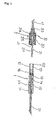
- Fig. 1 there is shown one embodiment of the infusion rate adjusting device of the present invention, which comprises a flow control unit 1 provided with plural numbers of check valves 13, 14, 15 of a duck bill type, said check valves 13, 14, 15 being arranged in series and in descending order of the opening pressures from an upstream side to a downstream side; and a check valve selecting means unit 2 including a tubular rod 21 capable of being passed through the check valves 13, 14, 15 to select one check valve 13 or 14 or 15 that determines a infusion rate.
- the infusion rate is determined by the check valve 13 or 14 or 15 that has not been penetrated by the rod 21 and located in the uppermost streamside of the passage.
- the flow control unit 1 includes a tubular body composed of a distal member 11 and a proximal member 12.
- the distal member 11 has a stepped lumen and is provided with plural numbers of check valves 13, 14, 15 of a duck bill type having different opening pressures.
- the check valves 13, 14, 15 are arranged within a large-sized lumen 111 of the distal member 11 in series and in the descending order of the opening pressures from an upstream side (i.e., a proximal side) to a downstream side (a distal side) of the lumen or passage of the distal member 11.
- the distal member 11 is provided at the distal end thereof with a connecting tube 31 that is to be connected to a connector 3, by fitting its one end in a small-sized lumen.
- the proximal member 12 has a lumen 121 formed into a complementary configuration with respect to an engaging portion 22 of the rod 21 of the check valve selecting means 2.
- The.proximal member 12 is provided at the proximal end thereof with a male engaging means or external thread 122 to fix the check valve selecting means 2 to the flow control unit 1 by engagement with a female engaging member 22 of the check valve selecting means 2 as mentioned below.
- the proximal member 12 is provided at the distal end thereof with an O-ring 16 to form a liquid-tight seal between the lumen 121 of the proximal member 12 and an outer wall of the rod 21 inserted therein.
- the O-ring 16 is located at a position close to the check valve 13 of the uppermost stream side that has the largest opening pressure, when the proximal member 12 is incorporated into the flow control unit 1.
- the check valve selecting means 2 has a distal end and a proximal end and is composed of a tubular rod 21 capable of being passed through the check valves 13, 14, 15; and a female engaging member 22 having female engaging means or internal thread 23 and rotatably fitted on the rod 21 at the proximal end thereof.
- the check valve selecting means 2 is connected at the proximal end thereof to a connecting tube 41 by inserting one end thereof into the lumen of the rod 21.
- the other end of the connecting tube 41 is connected to the flow control device 4 illustrated in Fig. 5.
- the drug solution flowing out of the flow control device 4 flows into the lumen 215 of the rod 21 through the connecting tube 41.
- the rod 21 is a slender hollow member composed of a relatively small-diameter portion 211 to be inserted into the flow control unit 1, and a relatively large-diameter portion 212 on which the female engaging member 22 is rotatably fitted.
- the female engaging member 22 is a hollow cylindrical member provided with an internal thread serving as the female engaging means 23.
- the female engaging member 22 is rotatable around the rod 21 and movable between an annular flange 213 provided on the proximal end of the rod 21 and an annular rib 214 provided on the relatively large-diameter portion 212 of the rod 21 at a position spaced from the annular flange 213 toward the distal side of the rod 21.
- the infusion rate adjusting device C is located at the downstream side from the flow control device 4 and adjusts the flow rate of the drug solution which had been discharged from the reservoir 7 and controlled by the flow control device 4 to the desired flow rate.
- numeral 3 is a connector
- 31, 41, 51 and 71 each indicates a connecting tube
- 5 indicates a filter
- 6 is a clamp.
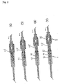
- the infusion rate is adjusted by the infusion rate-adjusting device C of Fig. 1 in the following manner mentioned hereinafter with reference to Fig. 2.
- FIG. 2 illustrates the infusion rate adjusting device C under the condition where none of the check valves 13, 14 and 15 is penetrated by the rod 21 of the check valve selecting means 2.
- the infusion rate is determined by the check valve 13 with the highest opening pressure, which is located at the uppermost stream of the lumen of the flow control unit 1.
- FIG. (B) illustrates the infusion rate-adjusting device C under the condition where only the check valve 13 has been penetrated by the rod 21 of the check valve selecting means 2. Thus, the infusion rate is determined or adjusted by the check valve 14 with the middle opening pressure.
- (C) illustrates the infusion rate adjusting device C under the condition where the check valves 13 and 14 have been penetrated by the rod 21 of the check valve selecting means 2. Thus, the infusion rate is determined or adjusted by the lowermost stream check valve 15.
- (D) illustrates the infusion rate adjusting device C under the condition where all the check valves 13, 14 and 15 have been penetrated by the rod 21 of the check valve selecting means 2. Thus, adjustment of the infusion rate is never carried out.
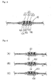
- FIG. 3 there is illustrated another embodiment of the present invention, which will be explained below with reference to Figs. 3 and 4.
- the flow control unit 10 is provided with plural check valves 102, 103 and 104 of an umbrella type having an opening pressure different from one another and arranged in series in the order of decreasing opening pressures.
- Each of the check valves 101, 102 and 103 has a drug passage 104, 105, 106 on the axis thereof.
- passage-blocking means 201, 202, 203 for blocking the drug passage 104, 105, 106 of the check valves 101, 102, 103 are used as the check valve selecting means 20.
- the check valve 101, 102 or 103 with the blocked drug passage 104, 105 or 106 serves as the check valve.
- the infusion rate is adjusted in the following manner mentioned below with reference to Fig. 4.
- FIG. 4 illustrates the infusion rate-adjusting device under the condition where the drug passage 104 of the check valve 101 is blocked by the passage-blocking means 201.
- the infusion rate is determined or adjusted by the opening pressure of the check valve 101.
- (B) illustrates the infusion rate-adjusting device under the condition where the drug passage 105 of the check valve 102 is blocked by the passage-blocking means 202.
- the infusion rate is determined or adjusted by the opening pressure of the check valve 102.
- (C) illustrates the infusion rate-adjusting device under the condition where the drug passage 106 of the check valve 103 is blocked by the passage-blocking means 203.
- the infusion rate is determined or adjusted by the opening pressure of the check valve 103.
- infusion rate adjusting devices each having a structure shown in Fig. 1 and including check valves 13, 14 and 15 with opening pressures of 10kPa, 5kPa, 2.5kPa respectively. Also, there were prepared infusion rate adjusting devices each having a structure shown in Fig. 1 and including check valves 13, 14 and 15 with opening pressures of 30 kPa, 25 kPa, 12.5 kPa respectively.
- Example 1 Opening pressure of valve reduction in flow rate Opening pressure of valve reduction in flow rate valve 13 10 kPa 16% 30 kPa 50% valve 14 5 kPa 8.3% 25 kPa 43% valve 15 2.5 kPa 4.2% 12.5 kPa 21%
- the present invention makes it easy to perform operation for setting the infusion rate of the drug solution injectors by use of the infusion rate adjusting device of the present invention.
- the present invention makes it possible to provide the infusion rate-adjusting device for drug solution injectors with ease.
Landscapes
- Health & Medical Sciences (AREA)
- Heart & Thoracic Surgery (AREA)
- Hematology (AREA)
- Life Sciences & Earth Sciences (AREA)
- Engineering & Computer Science (AREA)
- Anesthesiology (AREA)
- Biomedical Technology (AREA)
- Veterinary Medicine (AREA)
- Public Health (AREA)
- General Health & Medical Sciences (AREA)
- Animal Behavior & Ethology (AREA)
- Vascular Medicine (AREA)
- Physics & Mathematics (AREA)
- Fluid Mechanics (AREA)
- Pulmonology (AREA)
- Infusion, Injection, And Reservoir Apparatuses (AREA)
- Flow Control (AREA)
- Check Valves (AREA)
Applications Claiming Priority (2)
| Application Number | Priority Date | Filing Date | Title |
|---|---|---|---|
| JP2000053236A JP4010005B2 (ja) | 2000-02-29 | 2000-02-29 | 薬液注入器の注入速度調整装置 |
| JP2000053236 | 2000-02-29 |
Publications (3)
| Publication Number | Publication Date |
|---|---|
| EP1129740A2 EP1129740A2 (en) | 2001-09-05 |
| EP1129740A3 EP1129740A3 (en) | 2002-06-12 |
| EP1129740B1 true EP1129740B1 (en) | 2004-06-09 |
Family
ID=18574651
Family Applications (1)
| Application Number | Title | Priority Date | Filing Date |
|---|---|---|---|
| EP01104416A Expired - Lifetime EP1129740B1 (en) | 2000-02-29 | 2001-02-26 | Infusion rate adjusting device for drug solution injector |
Country Status (4)
| Country | Link |
|---|---|
| US (1) | US6554805B2 (enExample) |
| EP (1) | EP1129740B1 (enExample) |
| JP (1) | JP4010005B2 (enExample) |
| DE (1) | DE60103674T2 (enExample) |
Cited By (1)
| Publication number | Priority date | Publication date | Assignee | Title |
|---|---|---|---|---|
| EP3669909B1 (en) * | 2015-12-10 | 2023-08-23 | Nipro Corporation | Medical liquid administration device |
Families Citing this family (50)
| Publication number | Priority date | Publication date | Assignee | Title |
|---|---|---|---|---|
| US6679865B2 (en) * | 2001-12-07 | 2004-01-20 | Nedrip Ltd. | Fluid flow meter for gravity fed intravenous fluid delivery systems |
| US10022078B2 (en) | 2004-07-13 | 2018-07-17 | Dexcom, Inc. | Analyte sensor |
| US20080119703A1 (en) | 2006-10-04 | 2008-05-22 | Mark Brister | Analyte sensor |
| US8886273B2 (en) | 2003-08-01 | 2014-11-11 | Dexcom, Inc. | Analyte sensor |
| US8626257B2 (en) | 2003-08-01 | 2014-01-07 | Dexcom, Inc. | Analyte sensor |
| US20190357827A1 (en) | 2003-08-01 | 2019-11-28 | Dexcom, Inc. | Analyte sensor |
| US7591801B2 (en) | 2004-02-26 | 2009-09-22 | Dexcom, Inc. | Integrated delivery device for continuous glucose sensor |
| US9135402B2 (en) | 2007-12-17 | 2015-09-15 | Dexcom, Inc. | Systems and methods for processing sensor data |
| US7920906B2 (en) | 2005-03-10 | 2011-04-05 | Dexcom, Inc. | System and methods for processing analyte sensor data for sensor calibration |
| US9247900B2 (en) | 2004-07-13 | 2016-02-02 | Dexcom, Inc. | Analyte sensor |
| US8425417B2 (en) | 2003-12-05 | 2013-04-23 | Dexcom, Inc. | Integrated device for continuous in vivo analyte detection and simultaneous control of an infusion device |
| US8287453B2 (en) | 2003-12-05 | 2012-10-16 | Dexcom, Inc. | Analyte sensor |
| US8423114B2 (en) | 2006-10-04 | 2013-04-16 | Dexcom, Inc. | Dual electrode system for a continuous analyte sensor |
| US8364231B2 (en) | 2006-10-04 | 2013-01-29 | Dexcom, Inc. | Analyte sensor |
| US11633133B2 (en) | 2003-12-05 | 2023-04-25 | Dexcom, Inc. | Dual electrode system for a continuous analyte sensor |
| US8364230B2 (en) | 2006-10-04 | 2013-01-29 | Dexcom, Inc. | Analyte sensor |
| US8425416B2 (en) | 2006-10-04 | 2013-04-23 | Dexcom, Inc. | Analyte sensor |
| US8808228B2 (en) | 2004-02-26 | 2014-08-19 | Dexcom, Inc. | Integrated medicament delivery device for use with continuous analyte sensor |
| US7347853B2 (en) * | 2004-05-12 | 2008-03-25 | C. R. Bard, Inc. | Catheter with removable extension |
| US8177760B2 (en) | 2004-05-12 | 2012-05-15 | C. R. Bard, Inc. | Valved connector |
| US7857760B2 (en) | 2004-07-13 | 2010-12-28 | Dexcom, Inc. | Analyte sensor |
| US9414777B2 (en) | 2004-07-13 | 2016-08-16 | Dexcom, Inc. | Transcutaneous analyte sensor |
| US7783333B2 (en) | 2004-07-13 | 2010-08-24 | Dexcom, Inc. | Transcutaneous medical device with variable stiffness |
| US7766886B2 (en) * | 2005-07-30 | 2010-08-03 | The Regents Of The University Of California | Drainage devices and methods |
| US20070078442A1 (en) * | 2005-08-24 | 2007-04-05 | Mayse Martin L | Tapered attachment for pleural catheter |
| BRPI0619742A2 (pt) * | 2005-12-12 | 2011-10-11 | Acu Rate Pty Ltd | conjuntos de controle de fluxo e de aplicação intravenosa |
| US8186384B2 (en) | 2006-01-17 | 2012-05-29 | Jms Co., Ltd. | Flow control apparatus and medical injection circuit using the same |
| US8447376B2 (en) | 2006-10-04 | 2013-05-21 | Dexcom, Inc. | Analyte sensor |
| US8275438B2 (en) | 2006-10-04 | 2012-09-25 | Dexcom, Inc. | Analyte sensor |
| US8478377B2 (en) | 2006-10-04 | 2013-07-02 | Dexcom, Inc. | Analyte sensor |
| US8562528B2 (en) | 2006-10-04 | 2013-10-22 | Dexcom, Inc. | Analyte sensor |
| US8449464B2 (en) | 2006-10-04 | 2013-05-28 | Dexcom, Inc. | Analyte sensor |
| US8298142B2 (en) | 2006-10-04 | 2012-10-30 | Dexcom, Inc. | Analyte sensor |
| US20080306434A1 (en) | 2007-06-08 | 2008-12-11 | Dexcom, Inc. | Integrated medicament delivery device for use with continuous analyte sensor |
| EP4468309A3 (en) | 2007-10-09 | 2024-12-11 | DexCom, Inc. | Integrated insulin delivery system with continuous glucose sensor |
| US8417312B2 (en) | 2007-10-25 | 2013-04-09 | Dexcom, Inc. | Systems and methods for processing sensor data |
| US9839395B2 (en) | 2007-12-17 | 2017-12-12 | Dexcom, Inc. | Systems and methods for processing sensor data |
| US8396528B2 (en) | 2008-03-25 | 2013-03-12 | Dexcom, Inc. | Analyte sensor |
| CN102164627A (zh) * | 2008-07-25 | 2011-08-24 | 株式会社根本杏林堂 | 医学连接器装置 |
| US9149220B2 (en) | 2011-04-15 | 2015-10-06 | Dexcom, Inc. | Advanced analyte sensor calibration and error detection |
| US8574203B2 (en) | 2009-02-11 | 2013-11-05 | Becton, Dickinson And Company | Systems and methods for providing a flushable catheter assembly |
| US9155876B2 (en) | 2011-10-06 | 2015-10-13 | Becton, Dickinson And Company | Port valve of a blood control catheter |
| US9126012B2 (en) * | 2011-10-06 | 2015-09-08 | Becton, Dickinson And Company | Intravenous catheter with duckbill valve |
| US9155863B2 (en) | 2011-10-06 | 2015-10-13 | Becton, Dickinson And Company | Multiple use stretching and non-penetrating blood control valves |
| US9358364B2 (en) | 2011-10-06 | 2016-06-07 | Becton, Dickinson And Company | Activator attachment for blood control catheters |
| US9750925B2 (en) | 2014-01-21 | 2017-09-05 | Becton, Dickinson And Company | Ported catheter adapter having combined port and blood control valve with venting |
| US11007359B2 (en) * | 2017-02-16 | 2021-05-18 | Canadian Hospital Specialties Limited | Connector for catheter |
| US11331022B2 (en) | 2017-10-24 | 2022-05-17 | Dexcom, Inc. | Pre-connected analyte sensors |
| JP2021500162A (ja) | 2017-10-24 | 2021-01-07 | デックスコム・インコーポレーテッド | 事前接続された分析物センサ |
| US12246157B2 (en) * | 2019-01-14 | 2025-03-11 | Becton, Dickinson And Company | Needleless access connector facilitating instrument delivery to a catheter assembly |
Family Cites Families (12)
| Publication number | Priority date | Publication date | Assignee | Title |
|---|---|---|---|---|
| US3941149A (en) * | 1974-11-11 | 1976-03-02 | Baxter Laboratories, Inc. | Valve |
| US4246932A (en) * | 1979-10-18 | 1981-01-27 | Burron Medical, Inc. | Multiple additive valve assembly |
| US4729401A (en) * | 1987-01-29 | 1988-03-08 | Burron Medical Inc. | Aspiration assembly having dual co-axial check valves |
| US4756982A (en) * | 1987-11-09 | 1988-07-12 | General Motors Corporation | Dual seal battery vent valve |
| US4919167A (en) * | 1989-03-17 | 1990-04-24 | Manska Wayne E | Check valve |
| US5310094A (en) * | 1991-11-15 | 1994-05-10 | Jsp Partners, L.P. | Preservative free sterile fluid dispensing system |
| US5618268A (en) * | 1995-06-06 | 1997-04-08 | B. Braun Medical Inc. | Medical infusion devices and medicine delivery systems employing the same |
| DE29519322U1 (de) * | 1995-12-06 | 1996-02-15 | Jokisch, Thomas Michael, 45661 Recklinghausen | Rückschlagventil für Fluide mit geringen Druckunterschieden, insbesondere für die Medizintechnik und Aquaristik |
| JP3203636B2 (ja) | 1996-04-10 | 2001-08-27 | ニプロ株式会社 | 流量制御装置 |
| JP3266901B2 (ja) | 1996-07-17 | 2002-03-18 | ニプロ株式会社 | 多段式流量切換装置 |
| JP3269073B2 (ja) | 1996-10-15 | 2002-03-25 | ニプロ株式会社 | 多段式流量切り替え装置 |
| FR2776742B1 (fr) * | 1998-03-30 | 2000-06-02 | Medex Sa | Perfectionnement pour valve a seuil |
-
2000
- 2000-02-29 JP JP2000053236A patent/JP4010005B2/ja not_active Expired - Fee Related
-
2001
- 2001-02-26 EP EP01104416A patent/EP1129740B1/en not_active Expired - Lifetime
- 2001-02-26 DE DE60103674T patent/DE60103674T2/de not_active Expired - Lifetime
- 2001-02-28 US US09/794,136 patent/US6554805B2/en not_active Expired - Fee Related
Cited By (1)
| Publication number | Priority date | Publication date | Assignee | Title |
|---|---|---|---|---|
| EP3669909B1 (en) * | 2015-12-10 | 2023-08-23 | Nipro Corporation | Medical liquid administration device |
Also Published As
| Publication number | Publication date |
|---|---|
| US20010021829A1 (en) | 2001-09-13 |
| JP4010005B2 (ja) | 2007-11-21 |
| EP1129740A2 (en) | 2001-09-05 |
| DE60103674T2 (de) | 2004-10-21 |
| JP2001238950A (ja) | 2001-09-04 |
| US6554805B2 (en) | 2003-04-29 |
| DE60103674D1 (de) | 2004-07-15 |
| EP1129740A3 (en) | 2002-06-12 |
Similar Documents
| Publication | Publication Date | Title |
|---|---|---|
| EP1129740B1 (en) | Infusion rate adjusting device for drug solution injector | |
| US5190525A (en) | Drug infusion manifold | |
| EP1660173B1 (en) | A haemostasis device | |
| US6221065B1 (en) | Self-priming needle-free “Y”-adapter | |
| US7267669B2 (en) | Two site infusion apparatus | |
| US5356379A (en) | Disposable ambulatory infusion pump assembly | |
| US6638258B2 (en) | Automatic manifold for vascular catheter | |
| EP0497576B1 (en) | Combination valve | |
| DE69736754T2 (de) | Extrakorporales Schlitzventil und Steuerung für das Öffnen und Schliessen des Schlitzes | |
| EP3019214B1 (en) | Check valve system | |
| US12390582B2 (en) | Priming system for infusion devices | |
| US5224934A (en) | Patient controlled bolus dosage infuser | |
| US20090088724A1 (en) | Multiple Stage Fluid Delivery Device and Method of Use | |
| EP0211937A1 (en) | Apparatus for regulating the flow of fluid in medical apparatus | |
| WO2006118748A1 (en) | Outdwelling medical slit valves and related methods | |
| US20080067465A1 (en) | Liquid coinfusion unit | |
| US5217432A (en) | Automated drug infusion manifold | |
| DE4436540A1 (de) | Infusionssystem zur kontinuierlichen Abgabe eines flüssigen Medikaments unter Druck | |
| KR101687199B1 (ko) | 약액 주입기용 약액 공급밸브 | |
| US20080215014A1 (en) | Manually activated flow/no flow medical slit valves and related methods | |
| AU2020207989B2 (en) | Drug solution injection controller | |
| EP3424555B1 (en) | Valve device and use of such valve device as a back check valve in an intravenous system | |
| CN119499531A (zh) | 医用流体连接器 | |
| JP2007330800A (ja) | 薬液注入器の注入速度調整装置 | |
| IE20040569A1 (en) | A haemostasis device |
Legal Events
| Date | Code | Title | Description |
|---|---|---|---|
| PUAI | Public reference made under article 153(3) epc to a published international application that has entered the european phase |
Free format text: ORIGINAL CODE: 0009012 |
|
| AK | Designated contracting states |
Kind code of ref document: A2 Designated state(s): AT BE CH CY DE DK ES FI FR GB GR IE IT LI LU MC NL PT SE TR |
|
| AX | Request for extension of the european patent |
Free format text: AL;LT;LV;MK;RO;SI |
|
| PUAL | Search report despatched |
Free format text: ORIGINAL CODE: 0009013 |
|
| AK | Designated contracting states |
Kind code of ref document: A3 Designated state(s): AT BE CH CY DE DK ES FI FR GB GR IE IT LI LU MC NL PT SE TR |
|
| AX | Request for extension of the european patent |
Free format text: AL;LT;LV;MK;RO;SI |
|
| RIC1 | Information provided on ipc code assigned before grant |
Free format text: 7A 61M 5/168 A, 7A 61M 39/24 B, 7F 16K 15/14 B |
|
| 17P | Request for examination filed |
Effective date: 20020911 |
|
| 17Q | First examination report despatched |
Effective date: 20021203 |
|
| AKX | Designation fees paid |
Designated state(s): DE FR GB IT |
|
| GRAP | Despatch of communication of intention to grant a patent |
Free format text: ORIGINAL CODE: EPIDOSNIGR1 |
|
| GRAS | Grant fee paid |
Free format text: ORIGINAL CODE: EPIDOSNIGR3 |
|
| GRAA | (expected) grant |
Free format text: ORIGINAL CODE: 0009210 |
|
| AK | Designated contracting states |
Kind code of ref document: B1 Designated state(s): DE FR GB IT |
|
| REG | Reference to a national code |
Ref country code: GB Ref legal event code: FG4D |
|
| REF | Corresponds to: |
Ref document number: 60103674 Country of ref document: DE Date of ref document: 20040715 Kind code of ref document: P |
|
| REG | Reference to a national code |
Ref country code: IE Ref legal event code: FG4D |
|
| ET | Fr: translation filed | ||
| PLBE | No opposition filed within time limit |
Free format text: ORIGINAL CODE: 0009261 |
|
| STAA | Information on the status of an ep patent application or granted ep patent |
Free format text: STATUS: NO OPPOSITION FILED WITHIN TIME LIMIT |
|
| 26N | No opposition filed |
Effective date: 20050310 |
|
| PGFP | Annual fee paid to national office [announced via postgrant information from national office to epo] |
Ref country code: FR Payment date: 20120221 Year of fee payment: 12 |
|
| PGFP | Annual fee paid to national office [announced via postgrant information from national office to epo] |
Ref country code: DE Payment date: 20120222 Year of fee payment: 12 |
|
| PGFP | Annual fee paid to national office [announced via postgrant information from national office to epo] |
Ref country code: GB Payment date: 20120222 Year of fee payment: 12 Ref country code: IT Payment date: 20120218 Year of fee payment: 12 |
|
| GBPC | Gb: european patent ceased through non-payment of renewal fee |
Effective date: 20130226 |
|
| REG | Reference to a national code |
Ref country code: FR Ref legal event code: ST Effective date: 20131031 |
|
| REG | Reference to a national code |
Ref country code: DE Ref legal event code: R119 Ref document number: 60103674 Country of ref document: DE Effective date: 20130903 |
|
| PG25 | Lapsed in a contracting state [announced via postgrant information from national office to epo] |
Ref country code: IT Free format text: LAPSE BECAUSE OF NON-PAYMENT OF DUE FEES Effective date: 20130226 |
|
| PG25 | Lapsed in a contracting state [announced via postgrant information from national office to epo] |
Ref country code: DE Free format text: LAPSE BECAUSE OF NON-PAYMENT OF DUE FEES Effective date: 20130903 Ref country code: FR Free format text: LAPSE BECAUSE OF NON-PAYMENT OF DUE FEES Effective date: 20130228 Ref country code: GB Free format text: LAPSE BECAUSE OF NON-PAYMENT OF DUE FEES Effective date: 20130226 |