EP1128921B1 - Messeinrichtung für die rollenabstände bei einer stranggussanlage - Google Patents
Messeinrichtung für die rollenabstände bei einer stranggussanlage Download PDFInfo
- Publication number
- EP1128921B1 EP1128921B1 EP99956161A EP99956161A EP1128921B1 EP 1128921 B1 EP1128921 B1 EP 1128921B1 EP 99956161 A EP99956161 A EP 99956161A EP 99956161 A EP99956161 A EP 99956161A EP 1128921 B1 EP1128921 B1 EP 1128921B1
- Authority
- EP
- European Patent Office
- Prior art keywords
- dummy bar
- bar chain
- rolls
- links
- positions
- Prior art date
- Legal status (The legal status is an assumption and is not a legal conclusion. Google has not performed a legal analysis and makes no representation as to the accuracy of the status listed.)
- Expired - Lifetime
Links
Images

Classifications
-
- B—PERFORMING OPERATIONS; TRANSPORTING
- B22—CASTING; POWDER METALLURGY
- B22D—CASTING OF METALS; CASTING OF OTHER SUBSTANCES BY THE SAME PROCESSES OR DEVICES
- B22D11/00—Continuous casting of metals, i.e. casting in indefinite lengths
- B22D11/12—Accessories for subsequent treating or working cast stock in situ
- B22D11/128—Accessories for subsequent treating or working cast stock in situ for removing
- B22D11/1287—Rolls; Lubricating, cooling or heating rolls while in use
-
- B—PERFORMING OPERATIONS; TRANSPORTING
- B22—CASTING; POWDER METALLURGY
- B22D—CASTING OF METALS; CASTING OF OTHER SUBSTANCES BY THE SAME PROCESSES OR DEVICES
- B22D11/00—Continuous casting of metals, i.e. casting in indefinite lengths
- B22D11/08—Accessories for starting the casting procedure
-
- B—PERFORMING OPERATIONS; TRANSPORTING
- B22—CASTING; POWDER METALLURGY
- B22D—CASTING OF METALS; CASTING OF OTHER SUBSTANCES BY THE SAME PROCESSES OR DEVICES
- B22D11/00—Continuous casting of metals, i.e. casting in indefinite lengths
- B22D11/08—Accessories for starting the casting procedure
- B22D11/081—Starter bars
- B22D11/083—Starter bar head; Means for connecting or detaching starter bars and ingots
-
- B—PERFORMING OPERATIONS; TRANSPORTING
- B22—CASTING; POWDER METALLURGY
- B22D—CASTING OF METALS; CASTING OF OTHER SUBSTANCES BY THE SAME PROCESSES OR DEVICES
- B22D11/00—Continuous casting of metals, i.e. casting in indefinite lengths
- B22D11/12—Accessories for subsequent treating or working cast stock in situ
- B22D11/128—Accessories for subsequent treating or working cast stock in situ for removing
-
- B—PERFORMING OPERATIONS; TRANSPORTING
- B22—CASTING; POWDER METALLURGY
- B22D—CASTING OF METALS; CASTING OF OTHER SUBSTANCES BY THE SAME PROCESSES OR DEVICES
- B22D11/00—Continuous casting of metals, i.e. casting in indefinite lengths
- B22D11/16—Controlling or regulating processes or operations
Definitions
- This invention relates to continuous casting apparatus and more especially to apparatus for monitoring and sensing the positions of rolls which provide a path of travel for a continuously cast strand of metal as it solidifies.
- Conventional continuous casting machines comprise a water-cooled open-ended mould from which a partially solidified metal strand is withdrawn and moved along a curvilinear path defined between a plurality of spaced driven and/or idle rolls which engage opposite surfaces of the strand.
- the path of travel is generally vertical as the strand leaves the mould and generally horizontal as the solidified strand leaves the casting machine.
- the strand is moved along the path defined between the rolls by a flexible dummy bar chain which is secured to the strand.
- This chain is typically several metres long, is made of mild steel and weighs around 10 tonnes.
- Dummy bar chains having integral sensors for monitoring the condition and spacings between pairs of rolls are known.
- Known monitors include units comprising sensors and instrumentation electronics which form integral parts of one or more links of the chain.
- chain links are replaced by customised links which contain the required sensors and associated instrumentation.
- US-A-3937271 discloses apparatus for monitoring the positions of rolls of continuous casting machines which comprises a dummy bar chain having a block of integral position sensors.
- EP-B-0014862 discloses similar monitoring apparatus which comprises an integrated measuring device including sensors and a computer means with a store. Neither of these documents discloses roll position monitoring apparatus which comprises a dummy bar chain to which the monitoring apparatus is detachably secured. In both documents, the monitoring apparatus is exposed to hazards caused by the harsh environments of continuous casting even when no measurements of roll positions are required. In the present invention, the monitoring apparatus is removed from the dummy bar chain on occasions when measurements are not required.
- the environment within a continuous casting machine is particularly harsh. During casting relatively high temperatures are reached and water sprays are used to cool the strand. The resulting steam combines with the air, water mist sprays and running water to create an environment not conductive to longevity.
- the present invention sets out to provide apparatus for monitoring and sensing the positions, conditions and alignment of rolls and related equipment of continuous casting machines which do not suffer from, or at least alleviate, many of the disadvantages discussed above.
- apparatus for monitoring the positions of rolls of a continuous casting machine comprising a dummy bar chain to which is detachably secured monitoring apparatus which includes one or more sensors and associated electronic circuitry to monitor and sense the positions of rolls of a continuous casting machine, the apparatus being characterised in that the monitoring apparatus is attached to the dummy bar chain when the positions of the rolls are to be monitored and is detached therefrom when these positions are not to be monitored, the apparatus comprising a beam from the upper surface of which the sensors protrude and to the undersurface of which is secured a housing for the electronic circuitry, the beam being dimensioned to locate within indents formed in the upper surface of the links of the dummy bar chain with the housing positioned between opposed inner faces of these links.
- the dummy bar chain preferably includes a pair of side-by-side links shaped to receive the monitoring apparatus with the apparatus generally aligned both longitudinally and laterally with the dummy bar chain.
- Means may be provided for limited vertical movement of the monitoring apparatus relative to the dummy bar chain when the former is secured to the latter.
- This means may comprise one or more pivotably mounted links.
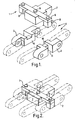
- the apparatus illustrated in Figure 1 of the drawings comprises monitoring apparatus 1 in accordance with the invention positioned above support links 2, 3 of a dummy bar chain 4.
- the monitoring apparatus 1 is a double or articulated unit which can readily be assembled onto or removed from the support links 2, 3 of the dummy bar chain.
- Monitoring apparatus 1 carries all necessary electronics and sensors to perform the required measurements.
- the apparatus 1 includes a beam 5 from the upper surface of which protrude sensors 6 (which may be spring loaded) and from the under surface of which is secured a housing 7 containing the required electronics. Monitors 8 are suspended from the beam ends and are selectively detachable therefrom.
- the chain links 2, 3 are shaped and dimensioned to receive the monitoring apparatus.
- the electronics housing 7 locates between the opposed inner faces 9 of the chain links 2, 3 and the beam is positioned within indents 10 formed in the supper surface of each support link.
- the monitors 8 extend into side channels 11 of the support links.
- Figure 2 illustrates the apparatus when assembled on the dummy bar chain. It will be seen that, when assembled, the support links define a carriage for the monitoring apparatus.
- the monitoring apparatus is able to float vertically to a limited extent relative to the support links of the dummy bar chain whereby either the upper or lower margin of the apparatus stands proud of the support links.
- the ability to float is in a single axis and ensures inter alia smooth transition to and from the dummy bar carriage. It also ensures that the monitoring apparatus is held onto the outer face of the casting rolls under inspection regardless of the amount of tension within the dummy bar chain. Springs may be provided for this purpose.
- the monitoring apparatus 1 may be connected to the chain links by one or more pivotably mounted links 14. These links operate to connect the monitoring apparatus to the support links which enable floating of the apparatus relative to the dummy bar chain.
- a multiplicity of measuring heads may be carried by the monitoring apparatus.
- These heads may include roll rotation units 15, bend sensors 16 and inclinometers 17.
- Measurements taken by the monitoring apparatus include the gaps between roll pairs of a continuous casting machine, tangential measurements of neighbouring rolls to provide measurements of roll alignment, roll rotation measurements, analyses of the water spray pattern within a casting machine and measurements of eccentricity of the centre of a roll when the roll is supported at and rotated about its bearings.
- Spring anvils 18 may also be provided to ensure contact of the measuring devices with the respective rolls.
- the loading/unloading procedure of the monitoring apparatus to/from the dummy bar chain has been designed to be a quick and simple procedure.
Landscapes
- Engineering & Computer Science (AREA)
- Mechanical Engineering (AREA)
- Continuous Casting (AREA)
- Encapsulation Of And Coatings For Semiconductor Or Solid State Devices (AREA)
Claims (5)
- Vorrichtung zur Überwachung der Positionen von Rollen einer Stranggußmaschine, welche Vorrichtung eine Hilfsstrangkette (4) aufweist, an der abnehmbar eine Überwachungsvorrichtung (1) festlegbar ist, die einen oder mehrere Sensoren (6) aufweist und der eine elektronische Schaltung zugeordnet ist, um die Positionen der Rollen einer Stranggußmaschine zu überwachen und abzutasten, dadurch gekennzeichnet, daß die Überwachungsvorrichtung (1) an der Hilfsstrangkette (4) befestigt ist, wenn die Positionen der Rollen überwacht werden sollen und die von der Hilfsstrangkette abgenommen wird, wenn diese Positionen nicht überwacht werden sollen, und daß die Vorrichtung einen Träger (5) aufweist, aus dessen oberer Oberfläche Sensoren (6) vorstehen und dessen Unterseite mit einem Gehäuse (7) für die elektronische Schaltung verbunden ist, und daß der Träger (5) so dimensioniert ist, daß er in Vertiefungen (10) einpaßt, die in der oberen Oberfläche der Kettenglieder (2, 3) der Hilfsstrangkette (4) angeordnet sind, wobei das Gehäuse (7) zwischen den gegenüberliegenden inneren Oberflächen dieser Glieder (2, 3) zu liegen kommt.
- Vorrichtung nach Anspruch 1, bei welcher Mittel vorgesehen sind, um eine begrenzte Vertikalbewegung der Überwachungsvorrichtung relativ zu der Hilfsstrangkette durchzuführen, wenn die Überwachungsvorrichtung an der Hilfsstrangkette befestigt ist.
- Vorrichtung nach Anspruch 2, bei welcher die die Bewegung begrenzenden Mittel aus einem schwenkbar gelagerten Lenker (14) oder mehreren schwenkbar gelagerten Lenkern (14) bestehen.
- Vorrichtung nach einem der vorhergehenden Ansprüche, bei welcher die Überwachungsvorrichtung eine schwenkbar angelenkte Einheit ist, die auf den Traggliedern der Hilfsstrangkette aufgesetzt bzw. entnommen werden kann.
- Vorrichtung nach Anspruch 4, bei welcher die vorstehenden Sensoren federbelastet sind.
Applications Claiming Priority (3)
| Application Number | Priority Date | Filing Date | Title |
|---|---|---|---|
| GB9824531 | 1998-11-10 | ||
| GBGB9824531.9A GB9824531D0 (en) | 1998-11-10 | 1998-11-10 | Continuous casting apparatus |
| PCT/GB1999/003698 WO2000027566A1 (en) | 1998-11-10 | 1999-11-10 | Measuring means for roller gaps in continuous casting apparatus |
Publications (2)
| Publication Number | Publication Date |
|---|---|
| EP1128921A1 EP1128921A1 (de) | 2001-09-05 |
| EP1128921B1 true EP1128921B1 (de) | 2003-03-19 |
Family
ID=10842115
Family Applications (1)
| Application Number | Title | Priority Date | Filing Date |
|---|---|---|---|
| EP99956161A Expired - Lifetime EP1128921B1 (de) | 1998-11-10 | 1999-11-10 | Messeinrichtung für die rollenabstände bei einer stranggussanlage |
Country Status (6)
| Country | Link |
|---|---|
| EP (1) | EP1128921B1 (de) |
| AT (1) | ATE234699T1 (de) |
| AU (1) | AU1281300A (de) |
| DE (1) | DE69906118T2 (de) |
| GB (1) | GB9824531D0 (de) |
| WO (1) | WO2000027566A1 (de) |
Cited By (2)
| Publication number | Priority date | Publication date | Assignee | Title |
|---|---|---|---|---|
| CN102410825B (zh) * | 2011-07-28 | 2013-08-14 | 西安重型技术有限责任公司 | 一种分体式辊缝测量仪 |
| CN108436051A (zh) * | 2017-02-16 | 2018-08-24 | 宝山钢铁股份有限公司 | 一种链节一体化的在线辊缝仪 |
Families Citing this family (3)
| Publication number | Priority date | Publication date | Assignee | Title |
|---|---|---|---|---|
| DE102006043797A1 (de) | 2006-09-19 | 2008-03-27 | Sms Demag Ag | Verfahren zum Stranggießen eines Metallstranges |
| GB0623755D0 (en) | 2006-11-28 | 2007-01-10 | Sarclad Ltd | Measuring system for continuous casting machines |
| CN104416135B (zh) * | 2013-08-30 | 2017-02-08 | 宝山钢铁股份有限公司 | 一种在方坯连铸轻压下拉矫机的辊缝标定方法 |
Family Cites Families (3)
| Publication number | Priority date | Publication date | Assignee | Title |
|---|---|---|---|---|
| JPS563149B2 (de) * | 1973-06-11 | 1981-01-23 | ||
| CH635928A5 (de) * | 1979-01-30 | 1983-04-29 | Concast Ag | Verfahren und vorrichtung zum ausmessen der strangfuehrung einer stranggiessanlage. |
| GB2188721B (en) * | 1986-04-04 | 1989-02-08 | British Steel Plc | Roll temperature measurement |
-
1998
- 1998-11-10 GB GBGB9824531.9A patent/GB9824531D0/en not_active Ceased
-
1999
- 1999-11-10 WO PCT/GB1999/003698 patent/WO2000027566A1/en active IP Right Grant
- 1999-11-10 AU AU12813/00A patent/AU1281300A/en not_active Abandoned
- 1999-11-10 EP EP99956161A patent/EP1128921B1/de not_active Expired - Lifetime
- 1999-11-10 AT AT99956161T patent/ATE234699T1/de not_active IP Right Cessation
- 1999-11-10 DE DE69906118T patent/DE69906118T2/de not_active Expired - Fee Related
Cited By (2)
| Publication number | Priority date | Publication date | Assignee | Title |
|---|---|---|---|---|
| CN102410825B (zh) * | 2011-07-28 | 2013-08-14 | 西安重型技术有限责任公司 | 一种分体式辊缝测量仪 |
| CN108436051A (zh) * | 2017-02-16 | 2018-08-24 | 宝山钢铁股份有限公司 | 一种链节一体化的在线辊缝仪 |
Also Published As
| Publication number | Publication date |
|---|---|
| AU1281300A (en) | 2000-05-29 |
| DE69906118T2 (de) | 2004-01-08 |
| ATE234699T1 (de) | 2003-04-15 |
| DE69906118D1 (de) | 2003-04-24 |
| WO2000027566A1 (en) | 2000-05-18 |
| EP1128921A1 (de) | 2001-09-05 |
| GB9824531D0 (en) | 1999-01-06 |
Similar Documents
| Publication | Publication Date | Title |
|---|---|---|
| US20080314938A1 (en) | Continuous Casting Plant Having at Least one Multifunction Robot | |
| US3937271A (en) | Measuring means for measuring secondary cooling zone roller gaps in continuous casting machine | |
| EP1182424B1 (de) | Vorrichtung zur Planheitsmessung an Bändern | |
| EP1128921B1 (de) | Messeinrichtung für die rollenabstände bei einer stranggussanlage | |
| SK84695A3 (en) | Method of continual casting of thin metal products between cylinders and device for its realization | |
| EP1537927B1 (de) | Segmentierte Rolle zum Stranggiessen | |
| US4762164A (en) | Mold friction monitoring for breakout protection | |
| US5850871A (en) | Foot guide and control system for continuous casting machine | |
| US4601324A (en) | Belt support for a twin-belt continuous casting mold | |
| KR101087448B1 (ko) | 주편 변형 감지 장치 | |
| US4903750A (en) | Continuous caster roll monitor | |
| CN102036770B (zh) | 辊诊断方法 | |
| KR20010048624A (ko) | 더미바 장착형 연속주조기 롤 검사장치 | |
| CA1179496A (en) | Apparatus for measuring eccentricity of rolls | |
| KR100530463B1 (ko) | 박슬래브 연속주조기의 롤 검사장치 및 그 검사방법 | |
| Pritchard et al. | The Monitoring of the Alignment of Continuous Casting Machines | |
| KR100843922B1 (ko) | 냉연강판 이송롤의 크라운 측정장치 | |
| JPS5935711B2 (ja) | 鋳片ブレ−クアウト予知検出装置 | |
| KR20090120419A (ko) | 롤 간격 측정장치 | |
| JP5009088B2 (ja) | 連続鋳造開始時の鋳型内湯面変動の防止方法 | |
| Mairy et al. | Mould oscillation monitoring for casting optimization | |
| CN116944440A (zh) | 集成光学传感器的导向辊以及连铸机 | |
| Nazzi | Measurement of roll bending in continuous slab casting machines | |
| EP1260292B1 (de) | Verfahren zum Detektieren eines versetzten Rollenteils einer Rolle | |
| KR101304789B1 (ko) | 롤 하중 측정장치 |
Legal Events
| Date | Code | Title | Description |
|---|---|---|---|
| PUAI | Public reference made under article 153(3) epc to a published international application that has entered the european phase |
Free format text: ORIGINAL CODE: 0009012 |
|
| 17P | Request for examination filed |
Effective date: 20010611 |
|
| AK | Designated contracting states |
Kind code of ref document: A1 Designated state(s): AT BE CH CY DE DK ES FI FR GB GR IE IT LI LU MC NL PT SE |
|
| 17Q | First examination report despatched |
Effective date: 20010919 |
|
| GRAH | Despatch of communication of intention to grant a patent |
Free format text: ORIGINAL CODE: EPIDOS IGRA |
|
| GRAH | Despatch of communication of intention to grant a patent |
Free format text: ORIGINAL CODE: EPIDOS IGRA |
|
| GRAA | (expected) grant |
Free format text: ORIGINAL CODE: 0009210 |
|
| AK | Designated contracting states |
Designated state(s): AT BE CH CY DE DK ES FI FR GB GR IE IT LI LU MC NL PT SE |
|
| PG25 | Lapsed in a contracting state [announced via postgrant information from national office to epo] |
Ref country code: LI Free format text: LAPSE BECAUSE OF FAILURE TO SUBMIT A TRANSLATION OF THE DESCRIPTION OR TO PAY THE FEE WITHIN THE PRESCRIBED TIME-LIMIT Effective date: 20030319 Ref country code: GR Free format text: LAPSE BECAUSE OF FAILURE TO SUBMIT A TRANSLATION OF THE DESCRIPTION OR TO PAY THE FEE WITHIN THE PRESCRIBED TIME-LIMIT Effective date: 20030319 Ref country code: FR Free format text: LAPSE BECAUSE OF FAILURE TO SUBMIT A TRANSLATION OF THE DESCRIPTION OR TO PAY THE FEE WITHIN THE PRESCRIBED TIME-LIMIT Effective date: 20030319 Ref country code: FI Free format text: LAPSE BECAUSE OF FAILURE TO SUBMIT A TRANSLATION OF THE DESCRIPTION OR TO PAY THE FEE WITHIN THE PRESCRIBED TIME-LIMIT Effective date: 20030319 Ref country code: CH Free format text: LAPSE BECAUSE OF FAILURE TO SUBMIT A TRANSLATION OF THE DESCRIPTION OR TO PAY THE FEE WITHIN THE PRESCRIBED TIME-LIMIT Effective date: 20030319 Ref country code: BE Free format text: LAPSE BECAUSE OF FAILURE TO SUBMIT A TRANSLATION OF THE DESCRIPTION OR TO PAY THE FEE WITHIN THE PRESCRIBED TIME-LIMIT Effective date: 20030319 Ref country code: AT Free format text: LAPSE BECAUSE OF FAILURE TO SUBMIT A TRANSLATION OF THE DESCRIPTION OR TO PAY THE FEE WITHIN THE PRESCRIBED TIME-LIMIT Effective date: 20030319 |
|
| REG | Reference to a national code |
Ref country code: GB Ref legal event code: FG4D |
|
| REG | Reference to a national code |
Ref country code: CH Ref legal event code: EP |
|
| REG | Reference to a national code |
Ref country code: IE Ref legal event code: FG4D |
|
| REF | Corresponds to: |
Ref document number: 69906118 Country of ref document: DE Date of ref document: 20030424 Kind code of ref document: P |
|
| PG25 | Lapsed in a contracting state [announced via postgrant information from national office to epo] |
Ref country code: SE Free format text: LAPSE BECAUSE OF FAILURE TO SUBMIT A TRANSLATION OF THE DESCRIPTION OR TO PAY THE FEE WITHIN THE PRESCRIBED TIME-LIMIT Effective date: 20030619 Ref country code: DK Free format text: LAPSE BECAUSE OF FAILURE TO SUBMIT A TRANSLATION OF THE DESCRIPTION OR TO PAY THE FEE WITHIN THE PRESCRIBED TIME-LIMIT Effective date: 20030619 |
|
| PG25 | Lapsed in a contracting state [announced via postgrant information from national office to epo] |
Ref country code: PT Free format text: LAPSE BECAUSE OF FAILURE TO SUBMIT A TRANSLATION OF THE DESCRIPTION OR TO PAY THE FEE WITHIN THE PRESCRIBED TIME-LIMIT Effective date: 20030620 |
|
| PG25 | Lapsed in a contracting state [announced via postgrant information from national office to epo] |
Ref country code: ES Free format text: LAPSE BECAUSE OF FAILURE TO SUBMIT A TRANSLATION OF THE DESCRIPTION OR TO PAY THE FEE WITHIN THE PRESCRIBED TIME-LIMIT Effective date: 20030930 |
|
| REG | Reference to a national code |
Ref country code: CH Ref legal event code: PL |
|
| PGFP | Annual fee paid to national office [announced via postgrant information from national office to epo] |
Ref country code: GB Payment date: 20031022 Year of fee payment: 5 |
|
| PG25 | Lapsed in a contracting state [announced via postgrant information from national office to epo] |
Ref country code: LU Free format text: LAPSE BECAUSE OF NON-PAYMENT OF DUE FEES Effective date: 20031110 Ref country code: IE Free format text: LAPSE BECAUSE OF NON-PAYMENT OF DUE FEES Effective date: 20031110 Ref country code: CY Free format text: LAPSE BECAUSE OF FAILURE TO SUBMIT A TRANSLATION OF THE DESCRIPTION OR TO PAY THE FEE WITHIN THE PRESCRIBED TIME-LIMIT Effective date: 20031110 |
|
| PGFP | Annual fee paid to national office [announced via postgrant information from national office to epo] |
Ref country code: NL Payment date: 20031128 Year of fee payment: 5 |
|
| PG25 | Lapsed in a contracting state [announced via postgrant information from national office to epo] |
Ref country code: MC Free format text: LAPSE BECAUSE OF NON-PAYMENT OF DUE FEES Effective date: 20031130 |
|
| PLBE | No opposition filed within time limit |
Free format text: ORIGINAL CODE: 0009261 |
|
| STAA | Information on the status of an ep patent application or granted ep patent |
Free format text: STATUS: NO OPPOSITION FILED WITHIN TIME LIMIT |
|
| PGFP | Annual fee paid to national office [announced via postgrant information from national office to epo] |
Ref country code: DE Payment date: 20040202 Year of fee payment: 5 |
|
| EN | Fr: translation not filed | ||
| 26N | No opposition filed |
Effective date: 20031222 |
|
| REG | Reference to a national code |
Ref country code: IE Ref legal event code: MM4A |
|
| PG25 | Lapsed in a contracting state [announced via postgrant information from national office to epo] |
Ref country code: GB Free format text: LAPSE BECAUSE OF NON-PAYMENT OF DUE FEES Effective date: 20041110 |
|
| PG25 | Lapsed in a contracting state [announced via postgrant information from national office to epo] |
Ref country code: NL Free format text: LAPSE BECAUSE OF NON-PAYMENT OF DUE FEES Effective date: 20050601 Ref country code: DE Free format text: LAPSE BECAUSE OF NON-PAYMENT OF DUE FEES Effective date: 20050601 |
|
| GBPC | Gb: european patent ceased through non-payment of renewal fee |
Effective date: 20041110 |
|
| NLV4 | Nl: lapsed or anulled due to non-payment of the annual fee |
Effective date: 20050601 |
|
| PG25 | Lapsed in a contracting state [announced via postgrant information from national office to epo] |
Ref country code: IT Free format text: LAPSE BECAUSE OF NON-PAYMENT OF DUE FEES Effective date: 20051110 |