EP1128491B1 - Elément de connecteur électrique - Google Patents
Elément de connecteur électrique Download PDFInfo
- Publication number
- EP1128491B1 EP1128491B1 EP01103809A EP01103809A EP1128491B1 EP 1128491 B1 EP1128491 B1 EP 1128491B1 EP 01103809 A EP01103809 A EP 01103809A EP 01103809 A EP01103809 A EP 01103809A EP 1128491 B1 EP1128491 B1 EP 1128491B1
- Authority
- EP
- European Patent Office
- Prior art keywords
- connection part
- conductor paths
- run
- plug connection
- part according
- Prior art date
- Legal status (The legal status is an assumption and is not a legal conclusion. Google has not performed a legal analysis and makes no representation as to the accuracy of the status listed.)
- Expired - Lifetime
Links
Images


Classifications
-
- H—ELECTRICITY
- H01—ELECTRIC ELEMENTS
- H01R—ELECTRICALLY-CONDUCTIVE CONNECTIONS; STRUCTURAL ASSOCIATIONS OF A PLURALITY OF MUTUALLY-INSULATED ELECTRICAL CONNECTING ELEMENTS; COUPLING DEVICES; CURRENT COLLECTORS
- H01R13/00—Details of coupling devices of the kinds covered by groups H01R12/70 or H01R24/00 - H01R33/00
- H01R13/02—Contact members
- H01R13/22—Contacts for co-operating by abutting
- H01R13/24—Contacts for co-operating by abutting resilient; resiliently-mounted
- H01R13/2407—Contacts for co-operating by abutting resilient; resiliently-mounted characterized by the resilient means
- H01R13/2421—Contacts for co-operating by abutting resilient; resiliently-mounted characterized by the resilient means using coil springs
-
- H—ELECTRICITY
- H01—ELECTRIC ELEMENTS
- H01R—ELECTRICALLY-CONDUCTIVE CONNECTIONS; STRUCTURAL ASSOCIATIONS OF A PLURALITY OF MUTUALLY-INSULATED ELECTRICAL CONNECTING ELEMENTS; COUPLING DEVICES; CURRENT COLLECTORS
- H01R4/00—Electrically-conductive connections between two or more conductive members in direct contact, i.e. touching one another; Means for effecting or maintaining such contact; Electrically-conductive connections having two or more spaced connecting locations for conductors and using contact members penetrating insulation
- H01R4/58—Electrically-conductive connections between two or more conductive members in direct contact, i.e. touching one another; Means for effecting or maintaining such contact; Electrically-conductive connections having two or more spaced connecting locations for conductors and using contact members penetrating insulation characterised by the form or material of the contacting members
- H01R4/64—Connections between or with conductive parts having primarily a non-electric function, e.g. frame, casing, rail
-
- H—ELECTRICITY
- H01—ELECTRIC ELEMENTS
- H01R—ELECTRICALLY-CONDUCTIVE CONNECTIONS; STRUCTURAL ASSOCIATIONS OF A PLURALITY OF MUTUALLY-INSULATED ELECTRICAL CONNECTING ELEMENTS; COUPLING DEVICES; CURRENT COLLECTORS
- H01R13/00—Details of coupling devices of the kinds covered by groups H01R12/70 or H01R24/00 - H01R33/00
- H01R13/66—Structural association with built-in electrical component
- H01R13/6608—Structural association with built-in electrical component with built-in single component
- H01R13/6625—Structural association with built-in electrical component with built-in single component with capacitive component
-
- H—ELECTRICITY
- H01—ELECTRIC ELEMENTS
- H01R—ELECTRICALLY-CONDUCTIVE CONNECTIONS; STRUCTURAL ASSOCIATIONS OF A PLURALITY OF MUTUALLY-INSULATED ELECTRICAL CONNECTING ELEMENTS; COUPLING DEVICES; CURRENT COLLECTORS
- H01R24/00—Two-part coupling devices, or either of their cooperating parts, characterised by their overall structure
- H01R24/60—Contacts spaced along planar side wall transverse to longitudinal axis of engagement
- H01R24/62—Sliding engagements with one side only, e.g. modular jack coupling devices
-
- H—ELECTRICITY
- H01—ELECTRIC ELEMENTS
- H01R—ELECTRICALLY-CONDUCTIVE CONNECTIONS; STRUCTURAL ASSOCIATIONS OF A PLURALITY OF MUTUALLY-INSULATED ELECTRICAL CONNECTING ELEMENTS; COUPLING DEVICES; CURRENT COLLECTORS
- H01R4/00—Electrically-conductive connections between two or more conductive members in direct contact, i.e. touching one another; Means for effecting or maintaining such contact; Electrically-conductive connections having two or more spaced connecting locations for conductors and using contact members penetrating insulation
- H01R4/24—Connections using contact members penetrating or cutting insulation or cable strands
- H01R4/2416—Connections using contact members penetrating or cutting insulation or cable strands the contact members having insulation-cutting edges, e.g. of tuning fork type
- H01R4/242—Connections using contact members penetrating or cutting insulation or cable strands the contact members having insulation-cutting edges, e.g. of tuning fork type the contact members being plates having a single slot
- H01R4/2425—Flat plates, e.g. multi-layered flat plates
-
- Y—GENERAL TAGGING OF NEW TECHNOLOGICAL DEVELOPMENTS; GENERAL TAGGING OF CROSS-SECTIONAL TECHNOLOGIES SPANNING OVER SEVERAL SECTIONS OF THE IPC; TECHNICAL SUBJECTS COVERED BY FORMER USPC CROSS-REFERENCE ART COLLECTIONS [XRACs] AND DIGESTS
- Y10—TECHNICAL SUBJECTS COVERED BY FORMER USPC
- Y10S—TECHNICAL SUBJECTS COVERED BY FORMER USPC CROSS-REFERENCE ART COLLECTIONS [XRACs] AND DIGESTS
- Y10S439/00—Electrical connectors
- Y10S439/941—Crosstalk suppression
Definitions
- the invention relates to a connector part, especially for RJ-45 connectors, according to the Preamble of claim 1.
- RJ-45 connector is a part according to DIN EN 60 603 7 / IEC 60 603-7 standardized and applied worldwide for connectors in communication and data networks.
- Conventional sockets for such RJ-45 connectors have a standardized arrangement of the contacts and the Geometry of the opening, also known as the mating face is, and have insulation piercing or Solder pins for connecting a data cable or for connecting on a printed circuit board.
- a connector is known from US Pat. No. 6,017,229 which the individual conductors in a compensation area partially crossed and one another has interposed dielectric film.
- This Connector has an undesirable in the direction of insertion great length and proves to be sensitive against screen surfaces (shields), as they are on the Are attached to the outside of the sockets to be inserted.
- EP 0 889 558 describes a special conductor arrangement described a connector which for the Capacitive and inductive coupling compensation between the individual conductors is particularly advantageous. However, this connector is not suitable for one Broadband transmission of category 6.
- Analog connectors are also from US 5,911,602 and US 5,938,479 known. The ones in these documents Disclosed connectors can meet the standards for Also do not meet Category 6 connectors and do not have a very compact design.
- RJ45 plug connections are included a definition for the design of the mating face, whereas for the course of the contacts from the mating area there are no regulations. Therefore, RJ45 plug connections are with a variety of different arranged conductor tracks known. Especially with RJ-45 connectors Category 5 is known for example from the cited document, the course arrange the conductor tracks in such a way that a targeted Crosstalk compensation occurs. All of these for one Signal bandwidth of 100 MHz plug connections has in common that it consists of the following, physical Reasons for higher bandwidths hardly or not at all are suitable. The mechanical dimensions of this Systems, especially the distance between the connector and Compensation, as well as the expansion of the compensations, are so big that at high frequencies one additional phase shift between the interference signal and the compensation signal occurs, which affects the effectiveness the existing compensation for these frequencies limits.
- the connector part according to the invention has a Compensation of crosstalk on, the compensation is extremely compact and both capacitive and also contains inductive coupling paths.
- the conductor tracks of the connector part have a minimal spatial Extension to.
- certain conductor tracks are crossed and for mutual compensation in two parallel planes, whereby between an electrical insulator to these two parallel planes or a dielectric is arranged around a to achieve capacitive coupling path.
- An advantage of the connector comprising the inventive Connector part is the fact that this even with signals with a bandwidth of 200 MHz only one Crosstalk of at most -48 dB.
- Another advantage is the fact that the connector part is very compact and small. This enables existing sockets by containing a socket the broadband connector part according to the invention exchange, thereby the bandwidth of existing Increase network. Those permanently installed in a building mutually twisted electrical conductors must be used not be replaced, which is an inexpensive Bandwidth expansion allowed.
- the connector part according to the invention can in addition to the 8-pin embodiment disclosed below also be designed with a different number of poles, for example in 6-pole Version according to the RJ11 standard.
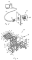
- FIG. 1 shows a computer 81 which is connected via a cable 82 to a communication network, also known as a LAN, connected.
- a communication network also known as a LAN
- cable 82 At the end of cable 82 is an RJ45 Plug 83 or an 8-pin module plug 83 arranged.
- the cable 82 comprises 4 pairs of each other twisted electrical conductor, also in English as "unshielded twisted pair (UTP)", and is for example for high bandwidth computer networks or suitable for high speeds.
- UTP unshielded twisted pair
- Behind a cover 84 the socket 85 or the module socket 85 is arranged, which has a first sub-housing 85a with a cavity 85c to insert the plug 83, and a second Part housing 85b includes.
- Fig. 2 shows a connector part 80 from the viewing direction B.
- Eight tracks 1-8 each have one at one end Contact spring 11-18 on and at the other end one each Output contact 71-78, which is designed as an insulation displacement terminal is.
- the contact springs 11-18 run along one Contact spring section 19 in a common area and mutually parallel.
- the contact springs 11-18 are in their V-shaped longitudinal direction and each have a contact point lla-18a, which at inserted plug 83 on the respective contact points of the plug 83 rest.
- the contact springs 11-18 start at one, facing away from the output contacts 71-78 End, and run to the output contacts 71-78.
- the contact springs 11-18 open into a deflection section 29, within which the conductor tracks 1-8 about Are deflected 90 degrees.
- crossover section 39 within which the conductor pairs 1,2; 4.5 and 7,8 cross each other.
- the partial lengths 41-48 arranged in section 49 of the conductor tracks 1-8 are partially in the longitudinal direction of the insulator 40 widely configured to be a to effect correspondingly greater capacity. Also are individual partial lengths 41-48 with respect to the insulator 40 arranged opposite, thereby also a increased capacity between the respective conductor tracks 1-8 to effect.
- the conductor tracks 1-8 open after the Section 49 in a deflection section 59, inside which deflects the conductor tracks 1-8 by about 90 degrees are.
- a crossover section 69 arranged, within which the conductors 1-8, as in 4b shown in a developed top view, cross.
- the crossover section 69 is subsequent an insulation displacement region 79 with insulation displacement contacts 71-78 arranged.
- the course of the conductor tracks 1-8 can also be configured in this way be at least some of the traces 1-8 cross each other in the deflection section 29, 59, so that the deflection section 29, 59 also the Crossover section 39, 69 corresponds.
- Fig. 3 shows the connector shown in Fig. 2 80 from viewing direction A. They are clearly visible Part lengths or formations 43.46 Conductors 3 and 6 in the area of section 49. Die Formations 43, 46 are only provided by the insulator 40 separately, opposite the formations 42, 45, 44, 48 and arranged mutually parallel.
- 4a shows the end of the plug 83 in a top view with the eight mutually parallel contact points 83b, which extend over a length 83a.
- 4b the course of the conductor tracks 1-8 is in one Level shown processed, from which in particular the Crossings of conductor tracks 1-8 in the connector part 80 can be seen.
- the very short designed contact spring section 19 opens into the Crossover section 39, in which the conductor tracks 1.2; 4.5 and 7.8 cross each other.
- the conductor tracks 1-8 run in section 49 in essentially mutually parallel, and, as in the figures 2, 3 and 6, in two mutually spaced Levels.
- the crossover section 69 the ends Conductor tracks 1-8 in the insulation displacement area 79. Die Sections 39, 49 and 69 together form one Compensation section 99, within which a targeted Crosstalk compensation is generated.
- FIG. 6 schematically shows a side view of the socket 85 with first partial housing 85a and second partial housing 85b. All contact springs 11-18 run in the same plane, whereby only the contact spring 11 with contact point 11a is designated. The course changes at the deflection point 29 of the conductor tracks 1-8 with respect to the alignment of the Contact springs 11-18 about 90 degrees. The conductor tracks 1-8 then run in two parallel planes, with the one level the conductor track sections 41, 42 and in the another level, the conductor track section 43 is shown. The isolator 40 is between these two levels arranged.
- This insulator 40 which serves as a dielectric can for example as a film, in particular as a PET film be designed. The film has a preferred Embodiment has a thickness of less than 0.3 mm.
- Fig. 5 shows the perspective view of a second Part housing 85b with part housing wall 85e and front wall 85f, in this part housing 85b the connector part 80 is arranged.
- the heads 1-8 are in Deflection section 29 between the brackets 85d of the held second sub-housing 85b.
- the insulator 40 is located on the front wall 85f.
- the sub-case 85b is as in Fig. 6, together with the first sub-housing 85a can be assembled into a socket 85. Since section 49 or the compensation section 99 essentially perpendicular to the longitudinal direction of the socket 85 is arranged, the beech 85 is in the longitudinal direction very short and compact.
- section 49 or the compensation section 99 with respect the longitudinal direction of the socket 85 approximately in the middle is arranged, the electrical compensation insensitive to metallic screen surfaces, which to use the Faraday effect on socket 85 can be attached. This gives the advantage that the same connector 80 for both shielded can also be used for unshielded connector systems.
- insulation displacement terminals can be used as output contacts 71-78 solder pin can also be provided.
- crossover section 69 can be dispensed with, so that Plug connection part 80 only in the crossover section 39 crossing conductor tracks 1-8.
- the conductor tracks could 1-8 be shaped in such a way that these are viewed from the side 6 a substantially Z-shaped Show course.
Landscapes
- Details Of Connecting Devices For Male And Female Coupling (AREA)
- Coupling Device And Connection With Printed Circuit (AREA)
- Feeding And Controlling Fuel (AREA)
- Solid-Sorbent Or Filter-Aiding Compositions (AREA)
- Non-Disconnectible Joints And Screw-Threaded Joints (AREA)
- Cable Accessories (AREA)
- Finger-Pressure Massage (AREA)
Claims (9)
- Elément de connecteur (80), en particulier pour des connecteurs RJ45, l'élément de connecteur comprenant une pluralité de voies conductrices (1-8) qui présentent un ressort de contact (11-18) à une extrémité et un contact de sortie (71-78) à l'autre extrémité, les ressorts de contact (11-18) allant depuis une extrémité située à l'opposé des contacts de sortie (71-78) jusqu'aux contacts de sortie (71-78), les voies conductrices (1-8) se croisant au moins en partie mutuellement dans une partie de compensation (99) succédant aux ressorts de contact (11-18), et les voies conductrices (1-8) courant le long d'une partie de la longueur de la partie de compensation (99) en étant au moins en partie mutuellement superposées et étant électriquement séparées au moyen d'un isolant (40) disposé entre elles, caractérisé en ce que les voies conductrices (1-8) ont un tracé essentiellement en forme de Z et l'isolant (40) est disposé dans un plan perpendiculaire à la direction d'enfichage.
- Elément de connecteur selon la revendication 1, caractérisé en ce que les ressorts de contact (11-18) sont situés dans une surface commune.
- Elément de connecteur selon l'une quelconque des revendications précédentes, caractérisé en ce que les ressorts de contact (11-18) sont configurés en forme de V dans la direction du tracé des voies conductrices (1-8).
- Elément de connecteur selon l'une quelconque des revendications précédentes, caractérisé en ce que les voies conductrices (1-8) sont tracées le long d'une partie de la longueur de la partie de compensation (99) dans deux plans parallèles, entre lesquels l'isolant (40) est disposé.
- Elément de connecteur selon l'une quelconque des revendications précédentes, caractérisé en ce que les voies conductrices (1-8) présentent dans la région de l'isolant (40) des parties déformées (43, 46), dont les surfaces sont dimensionnées de telle façon qu'il existe une capacité prédéterminée entre des voies conductrices déterminées (1-8).
- Elément de connecteur selon l'une quelconque des revendications précédentes, caractérisé en ce que les paires (1, 2; 3, 6; 7, 8) des voies conductrices (1-8) se croisent à l'intérieur de la partie de compensation (99).
- Elément de connecteur selon l'une quelconque des revendications précédentes, caractérisé en ce que le contact de sortie (71-78) a la forme d'une borne guillotine ou d'une broche à souder.
- Elément de connecteur selon l'une quelconque des revendications précédentes, caractérisé en ce que l'isolant (40) se présente sous la forme d'une feuille, en particulier d'une feuille de PET, et présente en particulier une épaisseur inférieure à 0,3 mm.
- Fiche comportant un élément de connecteur selon l'une quelconque des revendications précédentes.
Applications Claiming Priority (2)
| Application Number | Priority Date | Filing Date | Title |
|---|---|---|---|
| CH3272000 | 2000-02-21 | ||
| CH3272000 | 2000-02-21 |
Publications (3)
| Publication Number | Publication Date |
|---|---|
| EP1128491A2 EP1128491A2 (fr) | 2001-08-29 |
| EP1128491A3 EP1128491A3 (fr) | 2002-12-18 |
| EP1128491B1 true EP1128491B1 (fr) | 2004-09-15 |
Family
ID=4500503
Family Applications (1)
| Application Number | Title | Priority Date | Filing Date |
|---|---|---|---|
| EP01103809A Expired - Lifetime EP1128491B1 (fr) | 2000-02-21 | 2001-02-16 | Elément de connecteur électrique |
Country Status (6)
| Country | Link |
|---|---|
| US (1) | US6443776B2 (fr) |
| EP (1) | EP1128491B1 (fr) |
| AT (1) | ATE276594T1 (fr) |
| DE (1) | DE50103574D1 (fr) |
| ES (1) | ES2226995T3 (fr) |
| PL (1) | PL204762B1 (fr) |
Families Citing this family (31)
| Publication number | Priority date | Publication date | Assignee | Title |
|---|---|---|---|---|
| US20030082954A1 (en) * | 2001-11-01 | 2003-05-01 | Espenshade Leonard K. | Cross-talk reduced modular jack |
| US6796847B2 (en) * | 2002-10-21 | 2004-09-28 | Hubbell Incorporated | Electrical connector for telecommunications applications |
| US6964587B2 (en) * | 2002-11-10 | 2005-11-15 | Bel Fuse Ltd. | High performance, high capacitance gain, jack connector for data transmission or the like |
| CA2464834A1 (fr) | 2004-04-19 | 2005-10-19 | Nordx/Cdt Inc. | Connecteur |
| US7326089B2 (en) * | 2004-12-07 | 2008-02-05 | Commscope, Inc. Of North Carolina | Communications jack with printed wiring board having self-coupling conductors |
| US7168993B2 (en) | 2004-12-06 | 2007-01-30 | Commscope Solutions Properties Llc | Communications connector with floating wiring board for imparting crosstalk compensation between conductors |
| US7186149B2 (en) * | 2004-12-06 | 2007-03-06 | Commscope Solutions Properties, Llc | Communications connector for imparting enhanced crosstalk compensation between conductors |
| US7264516B2 (en) * | 2004-12-06 | 2007-09-04 | Commscope, Inc. | Communications jack with printed wiring board having paired coupling conductors |
| US7204722B2 (en) | 2004-12-07 | 2007-04-17 | Commscope Solutions Properties, Llc | Communications jack with compensation for differential to differential and differential to common mode crosstalk |
| US7166000B2 (en) * | 2004-12-07 | 2007-01-23 | Commscope Solutions Properties, Llc | Communications connector with leadframe contact wires that compensate differential to common mode crosstalk |
| US7220149B2 (en) * | 2004-12-07 | 2007-05-22 | Commscope Solutions Properties, Llc | Communication plug with balanced wiring to reduce differential to common mode crosstalk |
| US7186148B2 (en) * | 2004-12-07 | 2007-03-06 | Commscope Solutions Properties, Llc | Communications connector for imparting crosstalk compensation between conductors |
| US7320624B2 (en) * | 2004-12-16 | 2008-01-22 | Commscope, Inc. Of North Carolina | Communications jacks with compensation for differential to differential and differential to common mode crosstalk |
| WO2006081423A1 (fr) * | 2005-01-28 | 2006-08-03 | Commscope Inc. Of North Carolina | Connecteur commandé de conversion de mode pour diminution d’intermodulation extérieure |
| US7314393B2 (en) | 2005-05-27 | 2008-01-01 | Commscope, Inc. Of North Carolina | Communications connectors with floating wiring board for imparting crosstalk compensation between conductors |
| US20070293097A1 (en) * | 2006-06-15 | 2007-12-20 | Tyco Electronics Corporation | Modular plug electrical connector |
| FR2934425B1 (fr) * | 2008-07-28 | 2021-07-30 | Legrand France | Insert et procede d'assemblage d'un tel insert. |
| US7713094B1 (en) * | 2009-04-16 | 2010-05-11 | Leviton Manufacturing Co., Inc. | Telecommunications connector configured to reduce mode conversion coupling |
| US7909656B1 (en) * | 2009-10-26 | 2011-03-22 | Leviton Manufacturing Co., Inc. | High speed data communications connector with reduced modal conversion |
| EP2783469B1 (fr) | 2011-11-23 | 2016-06-22 | Panduit Corp. | Réseau de compensation utilisant une compensation orthogonale |
| US9136647B2 (en) | 2012-06-01 | 2015-09-15 | Panduit Corp. | Communication connector with crosstalk compensation |
| US8801473B2 (en) | 2012-09-12 | 2014-08-12 | Panduit Corp. | Communication connector having a plurality of conductors with a coupling zone |
| US9246463B2 (en) | 2013-03-07 | 2016-01-26 | Panduit Corp. | Compensation networks and communication connectors using said compensation networks |
| US9257792B2 (en) | 2013-03-14 | 2016-02-09 | Panduit Corp. | Connectors and systems having improved crosstalk performance |
| US9246274B2 (en) | 2013-03-15 | 2016-01-26 | Panduit Corp. | Communication connectors having crosstalk compensation networks |
| DE102013108131A1 (de) * | 2013-07-30 | 2015-02-05 | MCQ TECH GmbH | Kontaktsatz für eine Anschlussbuchse |
| CN108432064B (zh) * | 2014-06-05 | 2019-12-27 | 百富(澳门离岸商业服务)有限公司 | 具有接近补偿的网络接口连接器 |
| US10637196B2 (en) | 2015-11-11 | 2020-04-28 | Bel Fuse (Macao Commercial Offshore) Limited | Modular jack contact assembly having controlled capacitive coupling positioned within a jack housing |
| CN108475886B (zh) | 2015-11-11 | 2021-02-12 | 百富(澳门离岸商业服务)有限公司 | 模块化插座连接器 |
| US10530106B2 (en) | 2018-01-31 | 2020-01-07 | Bel Fuse (Macao Commercial Offshore) Limited | Modular plug connector with multilayer PCB for very high speed applications |
| CN114824954A (zh) * | 2021-01-18 | 2022-07-29 | 富士康(昆山)电脑接插件有限公司 | 电连接器 |
Family Cites Families (8)
| Publication number | Priority date | Publication date | Assignee | Title |
|---|---|---|---|---|
| DE69421798T2 (de) * | 1994-03-26 | 2004-07-15 | Molex Inc., Lisle | Verbinder vom Typ Modular Jack |
| US5769647A (en) * | 1995-11-22 | 1998-06-23 | The Siemon Company | Modular outlet employing a door assembly |
| US5791943A (en) * | 1995-11-22 | 1998-08-11 | The Siemon Company | Reduced crosstalk modular outlet |
| US5911602A (en) * | 1996-07-23 | 1999-06-15 | Superior Modular Products Incorporated | Reduced cross talk electrical connector |
| US5938479A (en) * | 1997-04-02 | 1999-08-17 | Communications Systems, Inc. | Connector for reducing electromagnetic field coupling |
| CH693012A5 (de) * | 1997-06-02 | 2003-01-15 | Reichle & De Massari Fa | Steckverbindungsteil für hochfrequente Datenübertragung über elektrische Leiter. |
| US6120329A (en) | 1998-05-08 | 2000-09-19 | The Whitaker Corporation | Modular jack with anti-cross-talk contacts and method of making same |
| US6106335A (en) * | 1998-06-05 | 2000-08-22 | Molex Incorporated | Crosstalk correction in electrical connectors |
-
2001
- 2001-02-16 AT AT01103809T patent/ATE276594T1/de active
- 2001-02-16 US US09/784,185 patent/US6443776B2/en not_active Expired - Lifetime
- 2001-02-16 EP EP01103809A patent/EP1128491B1/fr not_active Expired - Lifetime
- 2001-02-16 DE DE50103574T patent/DE50103574D1/de not_active Expired - Lifetime
- 2001-02-16 ES ES01103809T patent/ES2226995T3/es not_active Expired - Lifetime
- 2001-02-21 PL PL345989A patent/PL204762B1/pl unknown
Also Published As
| Publication number | Publication date |
|---|---|
| PL345989A1 (en) | 2001-08-27 |
| DE50103574D1 (de) | 2004-10-21 |
| US20010016455A1 (en) | 2001-08-23 |
| PL204762B1 (pl) | 2010-02-26 |
| ES2226995T3 (es) | 2005-04-01 |
| EP1128491A2 (fr) | 2001-08-29 |
| EP1128491A3 (fr) | 2002-12-18 |
| US6443776B2 (en) | 2002-09-03 |
| ATE276594T1 (de) | 2004-10-15 |
Similar Documents
| Publication | Publication Date | Title |
|---|---|---|
| EP1128491B1 (fr) | Elément de connecteur électrique | |
| DE60012107T2 (de) | Kapazitive Übersprechkompensation für einen Nachrichtensteckverbinder | |
| DE19822630C1 (de) | Anordnung von Kontaktpaaren zur Kompensation des Nahnebensprechens für eine elektrische Steckverbindung | |
| DE102006056001B4 (de) | Konfektionierbarer Rundsteckverbinder für Ethernet | |
| DE69931726T2 (de) | Buchsenartiger Steckverbinder mit Filtereinrichtung | |
| EP0674363B1 (fr) | Connecteur multipoles avec agencement de filtre | |
| DE60022434T2 (de) | Kapazitive Übersprechkompensationsschaltung für Kommunikationsverbinder | |
| DE69925126T2 (de) | Modularer Telekommunikationsverbinder mit Übersprechverringerung | |
| DE60129508T2 (de) | Kommunikationsverbinder mit Nebensprechkompensation | |
| DE60019170T2 (de) | Hochgeschwindigkeitsstecker und verbindung für leiterplatte | |
| DE102005042163B3 (de) | Schutzstecker für ein Anschlussmodul | |
| EP3044833A1 (fr) | Connecteur enfichable | |
| EP1236248B1 (fr) | Cable de raccordement avec fiche de raccordement electrique et barre de charge | |
| EP2979333B1 (fr) | Connecteur à compensation de diaphonie | |
| EP0889558B1 (fr) | Partie de connecteur électrique à fiches pour la transmission de données a hautefréquence sur des conducteurs électriques | |
| WO2008014891A1 (fr) | CONNECTEUR ENFICHABLE pour les techniques dE L'INFORMATIQUE ET DES TÉLÉCOMMUNICATIONS | |
| EP0991149A2 (fr) | Partie de connecteur électrique à fiches pour la transmission de données a hautefréquence sur des conducteurs électriques | |
| DE102007026102B3 (de) | Steckverbinder für Leiterplatten | |
| DE102009057260A1 (de) | Relief-Steckverbinder und Multilayerplatine | |
| EP1997194B1 (fr) | Connecteur pour la transmission de données et les télécommunications | |
| DE102020119282B4 (de) | Kontaktvorrichtung | |
| EP1313178B1 (fr) | Connecteur électrique pour la technologie de transfert de données | |
| DE102020115922A1 (de) | Steckverbinder und Steckverbinderadapter zur mehrfachen symmetrischen Signalübertragung | |
| DE10301278B4 (de) | Vorrichtung zur Verbindung von Leitern von Datenkabeln sowie Kabelmuffe mit einer derartigen Vorrichtung | |
| EP0865121A1 (fr) | Connecteur-adapteur pour la connection d'une connecteur à 4 pÔles à un connecteur à 8 pÔles selon la norme RJ45 |
Legal Events
| Date | Code | Title | Description |
|---|---|---|---|
| PUAI | Public reference made under article 153(3) epc to a published international application that has entered the european phase |
Free format text: ORIGINAL CODE: 0009012 |
|
| AK | Designated contracting states |
Kind code of ref document: A2 Designated state(s): AT BE CH CY DE DK ES FI FR GB GR IE IT LI LU MC NL PT SE TR |
|
| AX | Request for extension of the european patent |
Free format text: AL;LT;LV;MK;RO;SI |
|
| PUAL | Search report despatched |
Free format text: ORIGINAL CODE: 0009013 |
|
| AK | Designated contracting states |
Kind code of ref document: A3 Designated state(s): AT BE CH CY DE DK ES FI FR GB GR IE IT LI LU MC NL PT SE TR |
|
| AX | Request for extension of the european patent |
Free format text: AL;LT;LV;MK;RO;SI |
|
| RIC1 | Information provided on ipc code assigned before grant |
Free format text: 7H 01R 24/00 A, 7H 01R 13/514 B, 7H 01R 13/719 B |
|
| 17P | Request for examination filed |
Effective date: 20030214 |
|
| 17Q | First examination report despatched |
Effective date: 20030428 |
|
| AKX | Designation fees paid |
Designated state(s): AT BE CH CY DE DK ES FI FR GB GR IE IT LI LU MC NL PT SE TR |
|
| GRAP | Despatch of communication of intention to grant a patent |
Free format text: ORIGINAL CODE: EPIDOSNIGR1 |
|
| GRAS | Grant fee paid |
Free format text: ORIGINAL CODE: EPIDOSNIGR3 |
|
| GRAA | (expected) grant |
Free format text: ORIGINAL CODE: 0009210 |
|
| AK | Designated contracting states |
Kind code of ref document: B1 Designated state(s): AT BE CH CY DE DK ES FI FR GB GR IE IT LI LU MC NL PT SE TR |
|
| PG25 | Lapsed in a contracting state [announced via postgrant information from national office to epo] |
Ref country code: IE Free format text: LAPSE BECAUSE OF FAILURE TO SUBMIT A TRANSLATION OF THE DESCRIPTION OR TO PAY THE FEE WITHIN THE PRESCRIBED TIME-LIMIT Effective date: 20040915 Ref country code: FI Free format text: LAPSE BECAUSE OF FAILURE TO SUBMIT A TRANSLATION OF THE DESCRIPTION OR TO PAY THE FEE WITHIN THE PRESCRIBED TIME-LIMIT Effective date: 20040915 Ref country code: TR Free format text: LAPSE BECAUSE OF FAILURE TO SUBMIT A TRANSLATION OF THE DESCRIPTION OR TO PAY THE FEE WITHIN THE PRESCRIBED TIME-LIMIT Effective date: 20040915 |
|
| REG | Reference to a national code |
Ref country code: CH Ref legal event code: EP Ref country code: GB Ref legal event code: FG4D Free format text: NOT ENGLISH |
|
| REG | Reference to a national code |
Ref country code: IE Ref legal event code: FG4D Free format text: GERMAN |
|
| REF | Corresponds to: |
Ref document number: 50103574 Country of ref document: DE Date of ref document: 20041021 Kind code of ref document: P |
|
| PG25 | Lapsed in a contracting state [announced via postgrant information from national office to epo] |
Ref country code: GR Free format text: LAPSE BECAUSE OF FAILURE TO SUBMIT A TRANSLATION OF THE DESCRIPTION OR TO PAY THE FEE WITHIN THE PRESCRIBED TIME-LIMIT Effective date: 20041215 Ref country code: DK Free format text: LAPSE BECAUSE OF FAILURE TO SUBMIT A TRANSLATION OF THE DESCRIPTION OR TO PAY THE FEE WITHIN THE PRESCRIBED TIME-LIMIT Effective date: 20041215 |
|
| GBT | Gb: translation of ep patent filed (gb section 77(6)(a)/1977) |
Effective date: 20041202 |
|
| REG | Reference to a national code |
Ref country code: SE Ref legal event code: TRGR |
|
| REG | Reference to a national code |
Ref country code: CH Ref legal event code: NV Representative=s name: HANS ULRICH SEIFERT FELBER, SEIFERT & PARTNER |
|
| PG25 | Lapsed in a contracting state [announced via postgrant information from national office to epo] |
Ref country code: CY Free format text: LAPSE BECAUSE OF FAILURE TO SUBMIT A TRANSLATION OF THE DESCRIPTION OR TO PAY THE FEE WITHIN THE PRESCRIBED TIME-LIMIT Effective date: 20050216 Ref country code: LU Free format text: LAPSE BECAUSE OF NON-PAYMENT OF DUE FEES Effective date: 20050216 |
|
| PG25 | Lapsed in a contracting state [announced via postgrant information from national office to epo] |
Ref country code: MC Free format text: LAPSE BECAUSE OF NON-PAYMENT OF DUE FEES Effective date: 20050228 |
|
| REG | Reference to a national code |
Ref country code: ES Ref legal event code: FG2A Ref document number: 2226995 Country of ref document: ES Kind code of ref document: T3 |
|
| REG | Reference to a national code |
Ref country code: IE Ref legal event code: FD4D |
|
| PLBE | No opposition filed within time limit |
Free format text: ORIGINAL CODE: 0009261 |
|
| STAA | Information on the status of an ep patent application or granted ep patent |
Free format text: STATUS: NO OPPOSITION FILED WITHIN TIME LIMIT |
|
| ET | Fr: translation filed | ||
| 26N | No opposition filed |
Effective date: 20050616 |
|
| REG | Reference to a national code |
Ref country code: CH Ref legal event code: NV Representative=s name: HANS ULRICH SEIFERT SEIFERT & PARTNER |
|
| PG25 | Lapsed in a contracting state [announced via postgrant information from national office to epo] |
Ref country code: PT Free format text: LAPSE BECAUSE OF NON-PAYMENT OF DUE FEES Effective date: 20050215 |
|
| REG | Reference to a national code |
Ref country code: CH Ref legal event code: NV Representative=s name: THOMAS DAUB |
|
| REG | Reference to a national code |
Ref country code: DE Ref legal event code: R082 Ref document number: 50103574 Country of ref document: DE Representative=s name: PATENT- UND RECHTSANWALTSKANZLEI DAUB, DE Ref country code: DE Ref legal event code: R082 Ref document number: 50103574 Country of ref document: DE Representative=s name: DAUB UND KOLLEGEN, DE |
|
| PGFP | Annual fee paid to national office [announced via postgrant information from national office to epo] |
Ref country code: SE Payment date: 20140218 Year of fee payment: 14 Ref country code: NL Payment date: 20140218 Year of fee payment: 14 |
|
| PGFP | Annual fee paid to national office [announced via postgrant information from national office to epo] |
Ref country code: AT Payment date: 20140212 Year of fee payment: 14 Ref country code: BE Payment date: 20140218 Year of fee payment: 14 Ref country code: IT Payment date: 20140225 Year of fee payment: 14 Ref country code: ES Payment date: 20140226 Year of fee payment: 14 |
|
| REG | Reference to a national code |
Ref country code: FR Ref legal event code: PLFP Year of fee payment: 15 |
|
| PG25 | Lapsed in a contracting state [announced via postgrant information from national office to epo] |
Ref country code: BE Free format text: LAPSE BECAUSE OF NON-PAYMENT OF DUE FEES Effective date: 20150228 |
|
| REG | Reference to a national code |
Ref country code: NL Ref legal event code: V1 Effective date: 20150901 |
|
| REG | Reference to a national code |
Ref country code: SE Ref legal event code: EUG |
|
| PG25 | Lapsed in a contracting state [announced via postgrant information from national office to epo] |
Ref country code: NL Free format text: LAPSE BECAUSE OF NON-PAYMENT OF DUE FEES Effective date: 20150901 |
|
| REG | Reference to a national code |
Ref country code: AT Ref legal event code: MM01 Ref document number: 276594 Country of ref document: AT Kind code of ref document: T Effective date: 20150216 |
|
| PG25 | Lapsed in a contracting state [announced via postgrant information from national office to epo] |
Ref country code: AT Free format text: LAPSE BECAUSE OF NON-PAYMENT OF DUE FEES Effective date: 20150216 Ref country code: SE Free format text: LAPSE BECAUSE OF NON-PAYMENT OF DUE FEES Effective date: 20150217 |
|
| PG25 | Lapsed in a contracting state [announced via postgrant information from national office to epo] |
Ref country code: IT Free format text: LAPSE BECAUSE OF NON-PAYMENT OF DUE FEES Effective date: 20150216 |
|
| REG | Reference to a national code |
Ref country code: FR Ref legal event code: PLFP Year of fee payment: 16 |
|
| REG | Reference to a national code |
Ref country code: ES Ref legal event code: FD2A Effective date: 20160329 |
|
| PG25 | Lapsed in a contracting state [announced via postgrant information from national office to epo] |
Ref country code: ES Free format text: LAPSE BECAUSE OF NON-PAYMENT OF DUE FEES Effective date: 20150217 |
|
| REG | Reference to a national code |
Ref country code: CH Ref legal event code: PCAR Free format text: NEW ADDRESS: POSTFACH, 8058 ZUERICH-FLUGHAFEN (CH) |
|
| REG | Reference to a national code |
Ref country code: FR Ref legal event code: PLFP Year of fee payment: 17 |
|
| PGFP | Annual fee paid to national office [announced via postgrant information from national office to epo] |
Ref country code: CH Payment date: 20170217 Year of fee payment: 17 Ref country code: DE Payment date: 20170217 Year of fee payment: 17 Ref country code: FR Payment date: 20170217 Year of fee payment: 17 |
|
| PGFP | Annual fee paid to national office [announced via postgrant information from national office to epo] |
Ref country code: GB Payment date: 20170216 Year of fee payment: 17 |
|
| REG | Reference to a national code |
Ref country code: DE Ref legal event code: R119 Ref document number: 50103574 Country of ref document: DE |
|
| REG | Reference to a national code |
Ref country code: CH Ref legal event code: PL |
|
| GBPC | Gb: european patent ceased through non-payment of renewal fee |
Effective date: 20180216 |
|
| PG25 | Lapsed in a contracting state [announced via postgrant information from national office to epo] |
Ref country code: LI Free format text: LAPSE BECAUSE OF NON-PAYMENT OF DUE FEES Effective date: 20180228 Ref country code: CH Free format text: LAPSE BECAUSE OF NON-PAYMENT OF DUE FEES Effective date: 20180228 |
|
| REG | Reference to a national code |
Ref country code: FR Ref legal event code: ST Effective date: 20181031 |
|
| PG25 | Lapsed in a contracting state [announced via postgrant information from national office to epo] |
Ref country code: DE Free format text: LAPSE BECAUSE OF NON-PAYMENT OF DUE FEES Effective date: 20180901 |
|
| PG25 | Lapsed in a contracting state [announced via postgrant information from national office to epo] |
Ref country code: FR Free format text: LAPSE BECAUSE OF NON-PAYMENT OF DUE FEES Effective date: 20180228 Ref country code: GB Free format text: LAPSE BECAUSE OF NON-PAYMENT OF DUE FEES Effective date: 20180216 |