EP1128411A1 - Dispositif et procédé de surveillance d'appareil de coupure électrique et tableau électrique comportant un tel dispositif - Google Patents
Dispositif et procédé de surveillance d'appareil de coupure électrique et tableau électrique comportant un tel dispositif Download PDFInfo
- Publication number
- EP1128411A1 EP1128411A1 EP01410011A EP01410011A EP1128411A1 EP 1128411 A1 EP1128411 A1 EP 1128411A1 EP 01410011 A EP01410011 A EP 01410011A EP 01410011 A EP01410011 A EP 01410011A EP 1128411 A1 EP1128411 A1 EP 1128411A1
- Authority
- EP
- European Patent Office
- Prior art keywords
- operating member
- electrical
- light beam
- light
- signaling
- Prior art date
- Legal status (The legal status is an assumption and is not a legal conclusion. Google has not performed a legal analysis and makes no representation as to the accuracy of the status listed.)
- Granted
Links
- 238000012544 monitoring process Methods 0.000 title claims abstract description 12
- 238000000034 method Methods 0.000 title claims description 10
- 230000005540 biological transmission Effects 0.000 claims abstract description 25
- 230000005855 radiation Effects 0.000 claims abstract description 7
- 238000012806 monitoring device Methods 0.000 claims description 31
- 230000011664 signaling Effects 0.000 claims description 28
- 230000010287 polarization Effects 0.000 claims description 8
- 230000008859 change Effects 0.000 claims description 6
- 238000001514 detection method Methods 0.000 claims description 5
- 210000000056 organ Anatomy 0.000 claims description 4
- 230000007246 mechanism Effects 0.000 abstract description 2
- 230000001960 triggered effect Effects 0.000 description 7
- 238000010586 diagram Methods 0.000 description 6
- 238000004891 communication Methods 0.000 description 2
- 238000010521 absorption reaction Methods 0.000 description 1
- 230000009471 action Effects 0.000 description 1
- 230000000295 complement effect Effects 0.000 description 1
- 230000008878 coupling Effects 0.000 description 1
- 238000010168 coupling process Methods 0.000 description 1
- 238000005859 coupling reaction Methods 0.000 description 1
- 125000004122 cyclic group Chemical group 0.000 description 1
- 230000031700 light absorption Effects 0.000 description 1
- 230000008569 process Effects 0.000 description 1
- 238000012800 visualization Methods 0.000 description 1
Images


Classifications
-
- H—ELECTRICITY
- H01—ELECTRIC ELEMENTS
- H01H—ELECTRIC SWITCHES; RELAYS; SELECTORS; EMERGENCY PROTECTIVE DEVICES
- H01H71/00—Details of the protective switches or relays covered by groups H01H73/00 - H01H83/00
- H01H71/04—Means for indicating condition of the switching device
-
- H—ELECTRICITY
- H01—ELECTRIC ELEMENTS
- H01H—ELECTRIC SWITCHES; RELAYS; SELECTORS; EMERGENCY PROTECTIVE DEVICES
- H01H9/00—Details of switching devices, not covered by groups H01H1/00 - H01H7/00
- H01H9/16—Indicators for switching condition, e.g. "on" or "off"
- H01H9/168—Indicators for switching condition, e.g. "on" or "off" making use of an electromagnetic wave communication
Definitions
- the invention relates to a device and a method for monitoring a switching device.
- electric comprising means for supplying a state of at least one breaking device, as well as an electrical panel comprising an electrical equipment support, at least one electric cut-off device provided with an operating member, and such a device.
- Known monitoring devices are generally in the form of auxiliary modules intended to be fixed on electrical cut-off devices such as circuit breakers, switches, contactors or relays. These devices are linked with the mechanisms of said devices and provide outputs in the form of contacts representative of open, closed or triggered states depending on the type of device.
- each monitoring device requires intervention on each device for performing mechanical coupling and electrical connections.
- each monitoring device must be individually connected to the monitoring device visualization or status report.
- an alarm system for a plurality of circuit breakers has a light beam to detect the state of the circuit breakers.
- such system does not allow to determine the causes of opening of a device.
- the object of the invention is a device and a method for monitoring an electrical appliance. avoiding mechanical associations and electrical connections with devices electric and to signal the causes of opening of said devices, as well as a electrical panel comprising such a device.
- the transmission means comprise first emission means for emitting a first light beam intended to detect a position of the operating member representative of an open position of said electrical cutoff
- the receiving means comprise first means of reception intended to receive said first light beam
- the first light beam is modulated by a first signal having a first carrier frequency.
- the transmission means include second emission means for emitting a second light beam intended to detect a change of position of the operating member representative of an opening following a control of said electrical appliance, and the reception means comprise second reception means intended to receive said second light beam.
- the second light beam is modulated by a second signal having a second carrier frequency.
- control means connected to the second reception means include detection means for detecting a time of passage of the operating member in front of the second beam to differentiate a internal control of the operating member of an external control of the control member maneuver, an internal command being detected if a passage time is less than one predetermined time.
- the transmission means comprise third transmission means for emitting a third light beam intended to detect an external command from a operating member of said electrical appliance, and the reception means include third receiving means for receiving said third light beam.
- the third light beam is modulated by the first signal having a first carrier frequency
- the control means controlling the transmission in alternation of the first and third light beams according to a signal having a third predetermined frequency and duty cycle.
- the transmission means and the reception means comprise at least one polarization filter.
- the monitoring device includes reflection means of light beams arranged opposite the transmission means and reception means.
- the monitoring device includes means for of absorption of light beams arranged opposite the emission means and the means reception, and at least one operating member of said electrical appliance comprises a reflecting face for reflecting at least one light beam.
- the monitoring device includes signaling means connected to the control means to signal an opening state if at least one organ maneuver is in front of the first beam and if less an operating member has passed in front of the second beam for a time greater than a predetermined time or if a element was present in front of the third beam before the change in position of said element operating device.
- the monitoring device includes signaling means connected to the control means to signal a tripping state if at least one operating device is in front of the first beam and if at least one operating device is passed in front of the second beam for a time less than a predetermined time.
- the transmission means, the reception means, and the means of control are arranged in at least one modular switchgear module intended to be installed on a rail-shaped support.
- An electrical panel according to an embodiment of the invention comprising a support of electrical equipment and at least one electrical switching device provided with a maneuver comprises at least one monitoring device as defined above.
- the operating phase includes a third detection step an opening of an electrical appliance by an external command detected when actuator passes in front of the second beam for a time greater than one predetermined time and if said organ remains in front of the first beam, and a fourth step of signaling an opening when the third step is carried out.
- the operating phase includes a fifth signaling step a trigger and an opening if a third step is followed by a second step.
- the operating phase includes a sixth acknowledgment step to go from second or fifth step to fourth opening signaling stage.
- Modular electrical devices 1, 2, 3, 4 shown in Figure 1 have known monitoring devices such as auxiliary blocks 5, 6, 7, 8, 9, 10.
- the devices and auxiliary blocks are installed on a rail 11 forming a support.
- the auxiliary blocks are mechanically associated with the devices modular electrics.
- these auxiliary blocks include contacts electrical whose states are representative of the states of the devices, for example of the state open or closed, or the triggered state if the devices have triggering means.
- an electrical cut-off device monitoring device comprises means for emitting light radiation intended to be directed to an operating member of at least one electrical cut-off device, means for receiving a light radiation intended to be directed towards said member maneuver, and control means connected to the transmission means and to the means reception to determine the state of said at least one electrical cut-off device.
- the monitoring device comprises a first module 12 comprising a first transmission device 13 of a first light beam 14 directed towards an open position 15 of at least one member of operation of an electric cut-off device.
- the first light beam 14 is intended to detect a position of the operating member representative of a position open of said electrical cut-off device.
- the monitoring device comprises a second module 17 comprising a first receiving device 18 intended for receiving said first light beam 14.
- the devices 1 to 4 and the modules 12 and 17 are arranged on a rail 11 and aligned. If all the devices are closed, the operating devices of said devices are in a closed position 19 representative of closed devices and the beams 14 and 22 do not are not interrupted. In this case, the first receiving device 18 receives the first bundle 14 and module 17 control means can supply terminals 20 with a signal representative of closed electrical devices. If at least one device is open, a operating member passes into the open position 15, the first beam 14 is interrupted and the first receiving device 18 detects the interruption of the beam light and module 17 control means provide a signal representative of a device open.
- the first module 12 includes a second device 21 for emitting a second light beam 22 intended to detect a change of position of an operating member representative of an opening following a control of said electrical appliance
- the second module 17 comprises a second device reception 23.
- Control means of the second module connected to the second device 23 of reception detect a time of passage of the operating member in front of the second beam to differentiate an internal control of the operating member of a external control of the operating member, an internal control being detected if a passage time is less than a predetermined time. So if the passage time of the operating member 16 in front of the second beam 22 is less than a time predetermined, the control means can signal a triggering state of a apparatus. If the passage time is not less than a predetermined time, the means of control signal an opening of the device, in particular a manual opening.
- the predetermined time to differentiate internal commands from external commands is preferably between 4 and 20 ms.
- the devices and the monitoring device are arranged on a support in form of rail 11 and integrated into an electrical panel 24.
- the first light beam is modulated by a first signal having a first carrier frequency
- the second light beam is modulated by a second signal having a second carrier frequency
- the monitoring device includes a first module 12 comprising the first transmission device 13 of the first beam light 14 and the second device 23 for receiving the second light beam 22, and a second module 17 comprising the second transmission device 21 of the second beam light 22 and the first device 18 for receiving the first light beam 14.
- the module 12 includes a third transmission device for emitting a third light beam 25 intended to detect an external command of an operating member of said electrical appliance and the module 17 includes a third receiving device for receiving said third light beam.
- the third beam passes through a gripping zone 26 of an operating member 16.
- the module control means can interpret the opening action of the device as an external command or a manual opening command.
- FIG. 4 shows an apparatus 2 with an operating member 16, a module 12 and the arrangement of the three light beams with respect to said operating member.
- Figures 5, 6 and 7 show the passage of an actuator 16 from a position 19 representative of a closed device at a position representative of an open device.
- an operating member 16 begins to be actuated by a finger or a tool 27 which passes in front of the third light beam 25.
- the maneuver 16 passes in front of the second beam 22, and reaches the representative position 15 of an open device shown in Figure 7.
- the first beam is interrupted by the operating member 16. Since in this case the operating member 16 is moved manually, the passage time in front of the second beam is greater than one predetermined passage time and the control means detect an open position by an external operation.
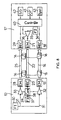
- FIG. 8 represents an electronic block diagram of a monitoring device according to the embodiment of FIG. 3.
- the first module 12 comprises the first transmitting device 13, the second receiving device 23, and a third emitting device 28 for emitting the third light beam 25.
- the second module 17 comprises the second transmission device 21, the first reception device 18, and a third receiving device 29 for receiving said third light beam 25.
- the control means comprise a circuit 30 generating a first signal 31 having a first carrier frequency. This signal 31 is applied to the first transmission device 13 through a first control circuit 32, and at third transmission device 28 through a third control circuit 33.
- the control means comprise a circuit 34 generating a second signal 35 having a second carrier frequency. This signal 35 is applied to the second transmission device 21 through a second control circuit 36.
- the first carrier frequency is approximately 40 kHz and the second carrier frequency is approximately 30 kHz.
- the first module 12 includes a third circuit 37 generating a third signal 38 having a modulation frequency.
- a control circuit 39 receives the modulation signal 38 and controls the control circuits 32 and 33 to emit the first and third beam alternately. So when the first transmitting device 13 transmits, the third device 28 is off, and when the third transmitting device 28 transmits the first device 13 is off.
- the modulation frequency is of the order of 5 kHz. he it is also possible to predetermine the duty cycle of the third signal 38.
- the reception 18 and 29 connected to a control circuit 40 of the second module 17 provide signals representative of light signals received.
- the control circuits 39 and 40 include synchronization means. So when the transmitting device 13 emits the beam 14, the signals supplied by the reception device 18 are taken into account by circuit 40 and the signals received by device 29 are ignored. Alternating next to the modulation signal 38, the transmission device 28 transmits the beam 25 signals supplied by the reception device 29 are taken into account by the circuit 40 and the signals received by the device 18 are ignored. Synchronization can be achieved by a link between the two control circuits 39 and 40.
- the module 17 includes a first signaling device 41 connected to the control 40 to signal an opening state of a device. Signaling occurs if at least one operating member is in front of the first beam 14 and if at least one member maneuver passed in front of the second beam 22 for a time greater than one predetermined time or if an element was present before the third beam before the change of position of said operating member.
- a second signaling device 42 is connected to the control circuit 40 to signal a tripping state if at least one operating member is in front of the first beam and if at least one operating member has passed in front of the second beam during a time less than a predetermined time.
- a second signaling circuit 43 connected to the control circuit 40 makes it possible to signal that the monitoring device is in working order and functioning properly.
- the reception device 23 is connected to circuit 39 and said circuit 39 can be connected to control circuit 40.
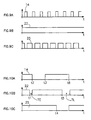
- FIGS. 9A to 9C represent signals representative of beam signals luminous used in a monitoring device according to the invention.
- the signal 14 is modulated at a modulation frequency identical to that of signal 25 of the Figure 9C.
- the modulation of said signals is alternative and complementary.
- the frequency of the modulation signal is approximately 1 kHz and the ratio cyclic is about one third for signal 14 and two thirds for signal 25.
- the signal 22 of FIG. 9B is continuous.
- signals represent the light beams respectively 14, 22 and 25 during a trip and an opening of a device.
- the beam 22 is interrupted for a time TC less than a predetermined time.
- the beam 14 is interrupted and the signaling device 42 is operated to indicate internal opening or tripping.
- the device is closed, the signaling is acknowledged and the monitoring device returns in are initial state.
- an operating member is actuated manually and the beam 25 is interrupted.
- the beam 22 is interrupted for a time TL greater than a predetermined time.
- the beam 14 is interrupted and the signaling device 41 is actuated to indicate an opening by a external or manual control.
- the signaling devices 41, 42 and 43 can be local on the modules and / or reported remotely, in particular by electrical links or communication buses.
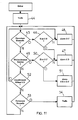
- FIG. 11 represents a flowchart of operation of a monitoring device according to one embodiment of the invention.
- the flowchart represents a process for switchgear monitoring to provide a status of at least one switching device break.
- the method comprises, in an operating phase, the emission of a first light beam for detecting a position of an actuator of at least one electrical cut-off device, and the emission of a second light beam to detect the movement of an operating member of at least one electric cut-off device.
- a step 44 of setting standby makes it possible to detect the various events.
- a step 45 makes it possible to detect a manual opening. If the opening manual is detected, a step 46 checks whether the triggered state is already detected for signal a device triggered at a signaling step 47, or to signal a device open to a signaling step 48 if the triggered state is not verified.
- a detection of an opening of an electrical device by an external control is detected when an operating member passes in front of the second beam for a longer time at a predetermined time and if said member remains in front of the first beam.
- a step 49 makes it possible to detect an internal trigger. If a trigger is detected, a step 50 checks whether the open state is already detected for signal an open device and a device triggered at a signaling step 51, or to signal a device triggered at signaling step 47 if the open state is not detected. In step 49, a detection of a triggering of an electrical appliance by a internal control is detected when an operating member passes in front of the second beam for a time less than a predetermined time and if said organ remains in front the first beam. Thus, if a triggering step 49 carried out follows a step 45 of manual opening performed, a step 51 signals the two opening events and trigger.
- a step 52 makes it possible to detect a fault acknowledgment command for tripping, in this case the open device signaling is commanded (step 48) if a previous signal indicated a device tripped (step 47 or 51).
- a step 53 makes it possible to detect a manual closure, in particular when the first beam is no longer interrupted. If the closure is detected, a step 54 of putting on standby cancels previous signals.
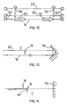
- the beams lights are polarized to avoid interference.
- the first beam has a first polarization and the third beam has a second polarization orthogonal to the first polarization.
- the polarization of the second beam can be identical to the polarization of the first beam.
- the treatment of polarization of the light beams can be achieved by polarizing filters arranged in front of the light beam emission and reception devices.
- the first light beam 14 may be the second light beam reflected by a reflector 58.
- the light beam reflector is preferably placed opposite the devices transmitting and receiving devices located, for example, in the same module.
- the beams luminous are absorbed by an absorption device 59 arranged opposite the devices transmitting and receiving devices located, for example, in the same module.
- the operating members have a reflective face for reflect the light beams towards reception devices.
- the transmitting devices and the receiving devices are preferably arranged in two modules arranged on a rail-shaped support.
- the modules are preferably located on each side of an electrical appliance or a group of several appliances aligned. It is also possible to arrange the transmitting and reception in a single module placed on one side of a device or group of devices.
- modules of the monitoring device can be arranged on each support to monitor different groups of devices. In other modes of As an embodiment, modules can also monitor devices on several supports. In a table signaling device states can be done by device, by group devices and / or for all devices in the switchboard.
- Signaling can be done locally on monitoring modules in the form of LEDs, relay contact outputs and / or in a form reported by means of communication with a central viewing or reporting facility.
Landscapes
- Burglar Alarm Systems (AREA)
- Train Traffic Observation, Control, And Security (AREA)
- Alarm Systems (AREA)
- Keying Circuit Devices (AREA)
- Operating, Guiding And Securing Of Roll- Type Closing Members (AREA)
- Gas-Insulated Switchgears (AREA)
- Selective Calling Equipment (AREA)
Abstract
Description
- des moyens d'émission d'au moins un rayonnement lumineux destinés à être dirigés vers un organe de manoeuvre d'au moins un appareil de coupure électrique pour détecter l'état et des commandes dudit appareil,
- des moyens de réception d'au moins un rayonnement lumineux destinés à être dirigés vers ledit organe de manoeuvre, et
- des moyens de contrôle connectés aux moyens d'émission et aux moyens de réception pour déterminer l'état et pour différencier des commandes internes et des commandes externes dudit au moins un appareil de coupure électrique.
- une première étape de détection d'un déclenchement d'un appareil électrique par une commande interne lorsqu'un organe de manoeuvre passe devant le second faisceau pendant un temps inférieur à un temps prédéterminé et si ledit organe reste devant le premier faisceau, et
- une seconde étape de signalisation d'un déclenchement lorsque la première étape est réalisée.
- la figure 1 représente des appareils modulaires comportant des blocs auxiliaires selon l'art antérieur ;
- la figure 2 montre un dispositif de surveillance selon un premier mode réalisation de l'invention pour surveiller des appareils électriques modulaires ;
- la figure 3 représente un dispositif de surveillance selon un second mode de réalisation de l'invention ;
- la figure 4 montre une vue de coté d'un appareil et d'un dispositif de surveillance selon un mode de réalisation de l'invention ;
- les figures 5, 6, et 7 montrent trois états de fonctionnement d'un dispositif selon un mode de réalisation de l'invention ;
- la figure 8 représente un schéma bloc électronique d'un dispositif de surveillance selon la figure 3 ;
- les figures 9A à 9C représentent des signaux représentatifs de signaux lumineux utilisés dans un dispositif de surveillance selon l'invention ;
- les figures 10A à 10C représentent des signaux selon les figures 9A à 9C pendant un déclenchement et une ouverture d'un appareil ;
- la figure 11 représente un organigramme de fonctionnement d'un dispositif de surveillance selon un mode de réalisation de l'invention ;
- la figure 12 montre un schéma représentant des signaux polarisés pour un dispositif selon un mode de réalisation de l'invention ;
- la figure 13 montre un schéma représentant des signaux réfléchis pour un dispositif selon un mode de réalisation de l'invention;
- la figure 14 montre un schéma représentant des signaux absorbés et réfléchis pour un dispositif selon un mode de réalisation de l'invention.
Claims (19)
- Dispositif de surveillance d'appareil de coupure électrique comportant des moyens pour fournir un état d'au moins un appareil (1, 2, 3, 4) de coupure,
caractérisé en ce qu'il comportedes moyens d'émission (13, 21, 28) d'au moins un rayonnement lumineux (14, 22, 25) destinés à être dirigés vers un organe (16) de manoeuvre d'au moins un appareil de coupure électrique (1,2, 3, 4) pour détecter l'état et des commandes dudit appareil,des moyens de réception (18, 23, 29) d'au moins un rayonnement lumineux (14, 22, 25) destinés à être dirigés vers ledit organe de manoeuvre (16), etdes moyens de contrôle (32, 33, 39, 36, 40) connectés aux moyens d'émission et aux moyens de réception pour déterminer l'état et pour différencier des commandes internes et des commandes externes dudit au moins un appareil de coupure électrique. - Dispositif selon la revendication 1 caractérisé en ce que les moyens d'émission comportent des premiers moyens d'émission (13) pour émettre un premier faisceau lumineux (14) destiné à détecter une position (15) de l'organe de manoeuvre représentative d'une position ouverte dudit appareil de coupure électrique, et les moyens de réception comportent des premiers moyens de réception (18) destinés à recevoir ledit premier faisceau lumineux (14).
- Dispositif selon la revendication 2 caractérisé en ce que le premier faisceau lumineux (14) est modulé par un premier signal (31) ayant une première fréquence de porteuse.
- Dispositif selon quelconque des revendications 1 à 3 caractérisé en ce que les moyens d'émission comportent des seconds moyens d'émission (21) pour émettre un second faisceau lumineux (22) destiné à détecter un changement de position de l'organe de manoeuvre (16) représentatif d'une ouverture suite à une commande dudit appareil électrique, et les moyens de réception comportent des seconds moyens de réception (23) destinés à recevoir ledit second faisceau lumineux (22).
- Dispositif selon la revendication 4 caractérisé en ce que le second faisceau lumineux (22) est modulé par un second signal (35) ayant une seconde fréquence de porteuse.
- Dispositif selon quelconque des revendications 3 à 5 caractérisé en ce que les moyens de contrôle (39, 40) connectés aux seconds moyens de réception (23) comportent des moyens de détection (39, 40) pour détecter un temps de passage de l'organe de manoeuvre (16) devant le second faisceau (22) pour différentier une commande interne de l'organe de manoeuvre d'une commande externe de l'organe de manoeuvre, une commande interne étant détectée si un temps de passage (TC) est inférieur à un temps prédéterminé.
- Dispositif selon quelconque des revendications 1 à 6 caractérisé en ce que les moyens d'émission comportent des troisièmes moyens d'émission (28) pour émettre un troisième faisceau lumineux (25) destiné à détecter une commande externe d'un organe de manoeuvre dudit appareil électrique, et les moyens de réception comportent des troisièmes moyens de réception (29) destinés à recevoir ledit troisième faisceau lumineux.
- Dispositif selon la revendication 7 caractérisé en ce que le troisième faisceau lumineux (25) est modulé par le premier signal (31) ayant une première fréquence de porteuse, les moyens de contrôle commandant l'émission en alternance des premier et troisième faisceaux lumineux (14, 25) selon un signal (38) ayant une troisième fréquence et un rapport cyclique prédéterminés.
- Dispositif selon quelconque des revendications 1 à 8 caractérisé en ce que les moyens d'émission et les moyens de réception comportent au moins un filtre (57) de polarisation.
- Dispositif selon quelconque des revendications 1 à 9 caractérisé en ce qu'il comporte des moyens de réflexion (58) de faisceaux lumineux disposés en face des moyens d'émission et des moyens de réception.
- Dispositif selon quelconque des revendications 1 à 10 caractérisé en ce qu'il comporte des moyens de d'absorption (59) de faisceaux lumineux disposés en face des moyens d'émission et des moyens de réception, et au moins un organe de manoeuvre dudit appareil électrique comporte une face réfléchissante (60) pour réfléchir au moins un faisceau lumineux.
- Dispositif selon quelconque des revendications 7 à 11 caractérisé en ce qu'il comporte des moyens de signalisation (41) connectés aux moyens de contrôle (40) pour signaler un état d'ouverture si au moins un organe de manoeuvre (16) est devant le premier faisceau et si moins un organe de manoeuvre est passé devant le second faisceau (22) pendant un temps (TL) supérieur à un temps prédéterminé ou si un élément (27) à été présent devant le troisième faisceau (25) avant le changement de position dudit organe de manoeuvre.
- Dispositif selon quelconque des revendications 3 à 12 caractérisé en ce qu'il comporte des moyens de signalisation (42) connectés aux moyens de contrôle pour signaler un état de déclenchement si au moins un organe de manoeuvre (16) est devant le premier faisceau (14) et si moins un organe de manoeuvre est passé devant le second faisceau (22) pendant un temps (TS) inférieur à un temps prédéterminé.
- Dispositif selon quelconque des revendications 1 à 13 caractérisé en ce que les moyens d'émission, les moyens de réception, et les moyens de contrôle sont disposés dans au moins un module (12, 17) de d'appareillage modulaire destiné à être installé sur un support (11) en forme de rail.
- Tableau électrique comportant un support (11) d'appareillage électrique et au moins un appareil électrique (1, 2, 3, 4) de coupure muni d'un organe de manoeuvre (16)
caractérisé en ce qu'il comporte au moins un dispositif de surveillance selon l'une quelconque des revendications 1 à 14. - Procédé de surveillance d'appareil de coupure électrique,
caractérisé en ce qu'il comporte dans une phase de fonctionnement l'émission d'un premier faisceau lumineux (14) pour détecter une position d'un organe de manoeuvre (16) d'au moins un appareil de coupure électrique (1, 2, 3, 4) et l'émission d'un second faisceau lumineux (22) pour détecter le déplacement d'un organe de manoeuvre (16) d'au moins un appareil de coupure électrique (1, 2, 3, 4), ladite phase de fonctionnement comportant :une première étape (49) de détection d'un déclenchement d'un appareil électrique par une commande interne lorsqu'un organe de manoeuvre passe devant le second faisceau pendant un temps (TC) inférieur à un temps prédéterminé et si ledit organe reste devant le premier faisceau, etune seconde étape (47) de signalisation d'un déclenchement lorsque la première étape est réalisée. - Procédé selon la revendication 16 caractérisé en ce que la phase de fonctionnement comporte une troisième étape (45) de détection d'une ouverture d'un appareil électrique par une commande externe détectée lorsqu'un organe de manoeuvre passe devant le second faisceau pendant un temps (TL) supérieur à un temps prédéterminé et si ledit organe reste devant le premier faisceau, et une quatrième étape (48) de signalisation d'une ouverture lorsque la troisième étape est réalisée.
- Procédé selon la revendication 17 caractérisé en ce que la phase de fonctionnement comporte une cinquième étape (51) de signalisation d'un déclenchement et d'une ouverture si une troisième étape est suivie d'une seconde étape.
- Procédé selon la revendication 18 caractérisé en ce que la phase de fonctionnement comporte une sixième étape (52) d'acquittement pour passer de la seconde ou de la cinquième étape à la quatrième étape (48) de signalisation d'ouverture.
Applications Claiming Priority (2)
| Application Number | Priority Date | Filing Date | Title |
|---|---|---|---|
| FR0002191A FR2805391B1 (fr) | 2000-02-22 | 2000-02-22 | Dispositif et procede de surveillance d'appareil de coupure electrique et tableau electrique comportant un tel dispositif |
| FR0002191 | 2000-02-22 |
Publications (2)
| Publication Number | Publication Date |
|---|---|
| EP1128411A1 true EP1128411A1 (fr) | 2001-08-29 |
| EP1128411B1 EP1128411B1 (fr) | 2009-08-12 |
Family
ID=8847254
Family Applications (1)
| Application Number | Title | Priority Date | Filing Date |
|---|---|---|---|
| EP01410011A Expired - Lifetime EP1128411B1 (fr) | 2000-02-22 | 2001-01-29 | Dispositif et procédé de surveillance d'appareil de coupure électrique et tableau électrique comportant un tel dispositif |
Country Status (6)
| Country | Link |
|---|---|
| EP (1) | EP1128411B1 (fr) |
| CN (1) | CN1224991C (fr) |
| AT (1) | ATE439679T1 (fr) |
| DE (1) | DE60139523D1 (fr) |
| ES (1) | ES2329007T3 (fr) |
| FR (1) | FR2805391B1 (fr) |
Cited By (2)
| Publication number | Priority date | Publication date | Assignee | Title |
|---|---|---|---|---|
| EP1808879A1 (fr) * | 2005-12-22 | 2007-07-18 | Siemens Aktiengesellschaft | Système destiné à la reconnaissance d'état sans contact |
| DE102006059134A1 (de) | 2006-12-14 | 2008-07-17 | Siemens Ag | Verteilerkasten mit Auslöseerkennung |
Families Citing this family (2)
| Publication number | Priority date | Publication date | Assignee | Title |
|---|---|---|---|---|
| JP4251197B2 (ja) * | 2005-11-29 | 2009-04-08 | セイコーエプソン株式会社 | ロボット制御装置及びロボットシステム |
| US9397462B2 (en) * | 2012-12-28 | 2016-07-19 | General Electric Company | Rail mounting system and detaching method |
Citations (3)
| Publication number | Priority date | Publication date | Assignee | Title |
|---|---|---|---|---|
| FR2690757A1 (fr) * | 1992-05-04 | 1993-11-05 | Alsthom Gec | Dispositif de détection de la présence d'une pièce mobile. |
| US5493278A (en) * | 1994-05-10 | 1996-02-20 | Eaton Corporation | Common alarm system for a plurality of circuit interrupters |
| DE29800372U1 (de) * | 1997-01-23 | 1998-04-02 | Siemens AG, 80333 München | Koppelsystem |
-
2000
- 2000-02-22 FR FR0002191A patent/FR2805391B1/fr not_active Expired - Fee Related
-
2001
- 2001-01-29 EP EP01410011A patent/EP1128411B1/fr not_active Expired - Lifetime
- 2001-01-29 ES ES01410011T patent/ES2329007T3/es not_active Expired - Lifetime
- 2001-01-29 AT AT01410011T patent/ATE439679T1/de not_active IP Right Cessation
- 2001-01-29 DE DE60139523T patent/DE60139523D1/de not_active Expired - Lifetime
- 2001-02-21 CN CN01104666.XA patent/CN1224991C/zh not_active Expired - Fee Related
Patent Citations (3)
| Publication number | Priority date | Publication date | Assignee | Title |
|---|---|---|---|---|
| FR2690757A1 (fr) * | 1992-05-04 | 1993-11-05 | Alsthom Gec | Dispositif de détection de la présence d'une pièce mobile. |
| US5493278A (en) * | 1994-05-10 | 1996-02-20 | Eaton Corporation | Common alarm system for a plurality of circuit interrupters |
| DE29800372U1 (de) * | 1997-01-23 | 1998-04-02 | Siemens AG, 80333 München | Koppelsystem |
Cited By (3)
| Publication number | Priority date | Publication date | Assignee | Title |
|---|---|---|---|---|
| EP1808879A1 (fr) * | 2005-12-22 | 2007-07-18 | Siemens Aktiengesellschaft | Système destiné à la reconnaissance d'état sans contact |
| DE102006059134A1 (de) | 2006-12-14 | 2008-07-17 | Siemens Ag | Verteilerkasten mit Auslöseerkennung |
| DE102006059134B4 (de) * | 2006-12-14 | 2008-10-02 | Siemens Ag | Verteilerkasten mit Auslöseerkennung |
Also Published As
| Publication number | Publication date |
|---|---|
| FR2805391A1 (fr) | 2001-08-24 |
| EP1128411B1 (fr) | 2009-08-12 |
| CN1310461A (zh) | 2001-08-29 |
| CN1224991C (zh) | 2005-10-26 |
| ES2329007T3 (es) | 2009-11-20 |
| ATE439679T1 (de) | 2009-08-15 |
| DE60139523D1 (de) | 2009-09-24 |
| FR2805391B1 (fr) | 2002-05-24 |
Similar Documents
| Publication | Publication Date | Title |
|---|---|---|
| EP0537084B1 (fr) | Disjoncteur à verrouillage sélectif | |
| EP1449287B1 (fr) | Module de commande et de protection d'un appareil interrupteur | |
| EP2018645A2 (fr) | Dispositif de surveillance de position d'une partie mobile d'un appareil electrique interrupteur | |
| FR2628549A1 (fr) | Systeme de commande de charges et procede pour deconnecter des bus secondaires d'un bus principal | |
| FR2819951A1 (fr) | Dispositif de distribution electrique, installation comportant un tel dispositif, et procede de protection electrique | |
| EP1128411B1 (fr) | Dispositif et procédé de surveillance d'appareil de coupure électrique et tableau électrique comportant un tel dispositif | |
| JPH10285788A (ja) | 漏電警報機能付き配線用遮断器 | |
| FR2947054A1 (fr) | Dispositif et procede d'indication de defauts electriques, ensemble et tableau electrique comportant un tel dispositif | |
| EP1393280B1 (fr) | Dispositif de securite | |
| CA2364846C (fr) | Systeme de distribution d'energie electrique et contacteur pour un tel systeme | |
| EP0874383A2 (fr) | Circuit de surveillance | |
| FR2580124A1 (fr) | ||
| EP3297111B1 (fr) | Dispositif et procede de surveillance de l'activite d'unites de traitement dans un declencheur electrique | |
| KR100826887B1 (ko) | 변전소 작동상태 모니터링을 위한 디지탈 모니터링시스템의 모듈화된 스위치모듈을 이용한 차단기 전원제어장치 | |
| EP0367688B1 (fr) | Procédé et dispositif de détection de coupure de la ligne de transmission d'un automate de gestion technique de bâtiment | |
| EP0097661B1 (fr) | Procede et systemes de teletransmission radio pour la commande d'un dispositif de signalisation ou d'appel a l'aide | |
| JP2529451B2 (ja) | 光通信ユニット | |
| EP0898408A1 (fr) | Dispositif et procédé de communication | |
| BE406832A (fr) | ||
| FR2514944A1 (fr) | Interrupteurs et relais electromecaniques a contacts autocontroles | |
| FR2611915A1 (fr) | Detecteur d'anomalie de fonctionnement d'un dispositif electrique, electrotechnique ou electronique | |
| BE894769A (fr) | Systeme pour la transmission de telegrammes d'ordres de postes transmetteurs differents a des postes recepteurs differents sur le meme canal de transmission | |
| JP2001145253A (ja) | 電気機械式開閉装置 | |
| FR2737040A1 (fr) | Coupe-circuit multipolaire haute intensite presentant une coupure au voisinage de zero du courant sur tous les contacts | |
| FR2826798A1 (fr) | Circuit d'alimentation d'une charge a partir d'une tension alternative, notamment du reseau electrique |
Legal Events
| Date | Code | Title | Description |
|---|---|---|---|
| PUAI | Public reference made under article 153(3) epc to a published international application that has entered the european phase |
Free format text: ORIGINAL CODE: 0009012 |
|
| AK | Designated contracting states |
Kind code of ref document: A1 Designated state(s): AT BE CH CY DE DK ES FI FR GB GR IE IT LI LU MC NL PT SE TR |
|
| AX | Request for extension of the european patent |
Free format text: AL;LT;LV;MK;RO;SI |
|
| 17P | Request for examination filed |
Effective date: 20011024 |
|
| AKX | Designation fees paid |
Free format text: AT BE CH CY DE DK ES FI FR GB GR IE IT LI LU MC NL PT SE TR |
|
| RAP1 | Party data changed (applicant data changed or rights of an application transferred) |
Owner name: SCHNEIDER ELECTRIC INDUSTRIES SAS |
|
| 17Q | First examination report despatched |
Effective date: 20080930 |
|
| GRAP | Despatch of communication of intention to grant a patent |
Free format text: ORIGINAL CODE: EPIDOSNIGR1 |
|
| RAP1 | Party data changed (applicant data changed or rights of an application transferred) |
Owner name: SCHNEIDER ELECTRIC INDUSTRIES SAS |
|
| RIN1 | Information on inventor provided before grant (corrected) |
Inventor name: LOVATO, JEAN-LOUIS, Inventor name: VERNAY MARC, |
|
| GRAS | Grant fee paid |
Free format text: ORIGINAL CODE: EPIDOSNIGR3 |
|
| GRAA | (expected) grant |
Free format text: ORIGINAL CODE: 0009210 |
|
| AK | Designated contracting states |
Kind code of ref document: B1 Designated state(s): AT BE CH CY DE DK ES FI FR GB GR IE IT LI LU MC NL PT SE TR |
|
| REG | Reference to a national code |
Ref country code: GB Ref legal event code: FG4D Free format text: NOT ENGLISH |
|
| REG | Reference to a national code |
Ref country code: CH Ref legal event code: EP |
|
| REG | Reference to a national code |
Ref country code: IE Ref legal event code: FG4D |
|
| REF | Corresponds to: |
Ref document number: 60139523 Country of ref document: DE Date of ref document: 20090924 Kind code of ref document: P |
|
| REG | Reference to a national code |
Ref country code: ES Ref legal event code: FG2A Ref document number: 2329007 Country of ref document: ES Kind code of ref document: T3 |
|
| PG25 | Lapsed in a contracting state [announced via postgrant information from national office to epo] |
Ref country code: AT Free format text: LAPSE BECAUSE OF FAILURE TO SUBMIT A TRANSLATION OF THE DESCRIPTION OR TO PAY THE FEE WITHIN THE PRESCRIBED TIME-LIMIT Effective date: 20090812 Ref country code: FI Free format text: LAPSE BECAUSE OF FAILURE TO SUBMIT A TRANSLATION OF THE DESCRIPTION OR TO PAY THE FEE WITHIN THE PRESCRIBED TIME-LIMIT Effective date: 20090812 Ref country code: SE Free format text: LAPSE BECAUSE OF FAILURE TO SUBMIT A TRANSLATION OF THE DESCRIPTION OR TO PAY THE FEE WITHIN THE PRESCRIBED TIME-LIMIT Effective date: 20090812 |
|
| NLV1 | Nl: lapsed or annulled due to failure to fulfill the requirements of art. 29p and 29m of the patents act | ||
| PG25 | Lapsed in a contracting state [announced via postgrant information from national office to epo] |
Ref country code: NL Free format text: LAPSE BECAUSE OF FAILURE TO SUBMIT A TRANSLATION OF THE DESCRIPTION OR TO PAY THE FEE WITHIN THE PRESCRIBED TIME-LIMIT Effective date: 20090812 |
|
| REG | Reference to a national code |
Ref country code: IE Ref legal event code: FD4D |
|
| PG25 | Lapsed in a contracting state [announced via postgrant information from national office to epo] |
Ref country code: PT Free format text: LAPSE BECAUSE OF FAILURE TO SUBMIT A TRANSLATION OF THE DESCRIPTION OR TO PAY THE FEE WITHIN THE PRESCRIBED TIME-LIMIT Effective date: 20091212 |
|
| PG25 | Lapsed in a contracting state [announced via postgrant information from national office to epo] |
Ref country code: DK Free format text: LAPSE BECAUSE OF FAILURE TO SUBMIT A TRANSLATION OF THE DESCRIPTION OR TO PAY THE FEE WITHIN THE PRESCRIBED TIME-LIMIT Effective date: 20090812 Ref country code: IE Free format text: LAPSE BECAUSE OF FAILURE TO SUBMIT A TRANSLATION OF THE DESCRIPTION OR TO PAY THE FEE WITHIN THE PRESCRIBED TIME-LIMIT Effective date: 20090812 |
|
| PLBE | No opposition filed within time limit |
Free format text: ORIGINAL CODE: 0009261 |
|
| STAA | Information on the status of an ep patent application or granted ep patent |
Free format text: STATUS: NO OPPOSITION FILED WITHIN TIME LIMIT |
|
| 26N | No opposition filed |
Effective date: 20100517 |
|
| BERE | Be: lapsed |
Owner name: SCHNEIDER ELECTRIC INDUSTRIES SAS Effective date: 20100131 |
|
| PG25 | Lapsed in a contracting state [announced via postgrant information from national office to epo] |
Ref country code: MC Free format text: LAPSE BECAUSE OF NON-PAYMENT OF DUE FEES Effective date: 20100131 |
|
| REG | Reference to a national code |
Ref country code: CH Ref legal event code: PL |
|
| GBPC | Gb: european patent ceased through non-payment of renewal fee |
Effective date: 20100129 |
|
| PG25 | Lapsed in a contracting state [announced via postgrant information from national office to epo] |
Ref country code: GR Free format text: LAPSE BECAUSE OF FAILURE TO SUBMIT A TRANSLATION OF THE DESCRIPTION OR TO PAY THE FEE WITHIN THE PRESCRIBED TIME-LIMIT Effective date: 20091113 Ref country code: LI Free format text: LAPSE BECAUSE OF NON-PAYMENT OF DUE FEES Effective date: 20100131 Ref country code: CH Free format text: LAPSE BECAUSE OF NON-PAYMENT OF DUE FEES Effective date: 20100131 |
|
| PG25 | Lapsed in a contracting state [announced via postgrant information from national office to epo] |
Ref country code: GB Free format text: LAPSE BECAUSE OF NON-PAYMENT OF DUE FEES Effective date: 20100129 |
|
| PG25 | Lapsed in a contracting state [announced via postgrant information from national office to epo] |
Ref country code: BE Free format text: LAPSE BECAUSE OF NON-PAYMENT OF DUE FEES Effective date: 20100131 |
|
| PG25 | Lapsed in a contracting state [announced via postgrant information from national office to epo] |
Ref country code: CY Free format text: LAPSE BECAUSE OF FAILURE TO SUBMIT A TRANSLATION OF THE DESCRIPTION OR TO PAY THE FEE WITHIN THE PRESCRIBED TIME-LIMIT Effective date: 20090812 |
|
| PG25 | Lapsed in a contracting state [announced via postgrant information from national office to epo] |
Ref country code: LU Free format text: LAPSE BECAUSE OF NON-PAYMENT OF DUE FEES Effective date: 20100129 |
|
| PG25 | Lapsed in a contracting state [announced via postgrant information from national office to epo] |
Ref country code: TR Free format text: LAPSE BECAUSE OF FAILURE TO SUBMIT A TRANSLATION OF THE DESCRIPTION OR TO PAY THE FEE WITHIN THE PRESCRIBED TIME-LIMIT Effective date: 20090812 |
|
| PGFP | Annual fee paid to national office [announced via postgrant information from national office to epo] |
Ref country code: DE Payment date: 20140110 Year of fee payment: 14 |
|
| PGFP | Annual fee paid to national office [announced via postgrant information from national office to epo] |
Ref country code: FR Payment date: 20140113 Year of fee payment: 14 |
|
| PGFP | Annual fee paid to national office [announced via postgrant information from national office to epo] |
Ref country code: ES Payment date: 20141211 Year of fee payment: 15 |
|
| PGFP | Annual fee paid to national office [announced via postgrant information from national office to epo] |
Ref country code: IT Payment date: 20150116 Year of fee payment: 15 |
|
| REG | Reference to a national code |
Ref country code: DE Ref legal event code: R119 Ref document number: 60139523 Country of ref document: DE |
|
| PG25 | Lapsed in a contracting state [announced via postgrant information from national office to epo] |
Ref country code: DE Free format text: LAPSE BECAUSE OF NON-PAYMENT OF DUE FEES Effective date: 20150801 |
|
| REG | Reference to a national code |
Ref country code: FR Ref legal event code: ST Effective date: 20150930 |
|
| PG25 | Lapsed in a contracting state [announced via postgrant information from national office to epo] |
Ref country code: FR Free format text: LAPSE BECAUSE OF NON-PAYMENT OF DUE FEES Effective date: 20150202 |
|
| PG25 | Lapsed in a contracting state [announced via postgrant information from national office to epo] |
Ref country code: IT Free format text: LAPSE BECAUSE OF NON-PAYMENT OF DUE FEES Effective date: 20160129 |
|
| REG | Reference to a national code |
Ref country code: ES Ref legal event code: FD2A Effective date: 20170228 |
|
| PG25 | Lapsed in a contracting state [announced via postgrant information from national office to epo] |
Ref country code: ES Free format text: LAPSE BECAUSE OF NON-PAYMENT OF DUE FEES Effective date: 20160130 |