EP1128235A2 - Vorrichtung zum manuellen Öffnen und Schliessen eines Gerätegehäuses - Google Patents
Vorrichtung zum manuellen Öffnen und Schliessen eines Gerätegehäuses Download PDFInfo
- Publication number
- EP1128235A2 EP1128235A2 EP01101675A EP01101675A EP1128235A2 EP 1128235 A2 EP1128235 A2 EP 1128235A2 EP 01101675 A EP01101675 A EP 01101675A EP 01101675 A EP01101675 A EP 01101675A EP 1128235 A2 EP1128235 A2 EP 1128235A2
- Authority
- EP
- European Patent Office
- Prior art keywords
- housing part
- unlocking
- locking
- housing
- handle
- Prior art date
- Legal status (The legal status is an assumption and is not a legal conclusion. Google has not performed a legal analysis and makes no representation as to the accuracy of the status listed.)
- Granted
Links
- 230000033001 locomotion Effects 0.000 claims abstract description 24
- 230000000284 resting effect Effects 0.000 claims abstract description 4
- 238000010438 heat treatment Methods 0.000 claims description 8
- 238000000034 method Methods 0.000 claims description 6
- 238000004804 winding Methods 0.000 claims description 2
- 238000000926 separation method Methods 0.000 description 2
- 230000005540 biological transmission Effects 0.000 description 1
- 239000011888 foil Substances 0.000 description 1
- 238000007726 management method Methods 0.000 description 1
- 238000013024 troubleshooting Methods 0.000 description 1
Images


Classifications
-
- G—PHYSICS
- G03—PHOTOGRAPHY; CINEMATOGRAPHY; ANALOGOUS TECHNIQUES USING WAVES OTHER THAN OPTICAL WAVES; ELECTROGRAPHY; HOLOGRAPHY
- G03G—ELECTROGRAPHY; ELECTROPHOTOGRAPHY; MAGNETOGRAPHY
- G03G15/00—Apparatus for electrographic processes using a charge pattern
- G03G15/20—Apparatus for electrographic processes using a charge pattern for fixing, e.g. by using heat
- G03G15/2003—Apparatus for electrographic processes using a charge pattern for fixing, e.g. by using heat using heat
- G03G15/2014—Apparatus for electrographic processes using a charge pattern for fixing, e.g. by using heat using heat using contact heat
- G03G15/2064—Apparatus for electrographic processes using a charge pattern for fixing, e.g. by using heat using heat using contact heat combined with pressure
-
- G—PHYSICS
- G03—PHOTOGRAPHY; CINEMATOGRAPHY; ANALOGOUS TECHNIQUES USING WAVES OTHER THAN OPTICAL WAVES; ELECTROGRAPHY; HOLOGRAPHY
- G03G—ELECTROGRAPHY; ELECTROPHOTOGRAPHY; MAGNETOGRAPHY
- G03G21/00—Arrangements not provided for by groups G03G13/00 - G03G19/00, e.g. cleaning, elimination of residual charge
- G03G21/16—Mechanical means for facilitating the maintenance of the apparatus, e.g. modular arrangements
- G03G21/1642—Mechanical means for facilitating the maintenance of the apparatus, e.g. modular arrangements for connecting the different parts of the apparatus
- G03G21/1647—Mechanical connection means
-
- G—PHYSICS
- G03—PHOTOGRAPHY; CINEMATOGRAPHY; ANALOGOUS TECHNIQUES USING WAVES OTHER THAN OPTICAL WAVES; ELECTROGRAPHY; HOLOGRAPHY
- G03G—ELECTROGRAPHY; ELECTROPHOTOGRAPHY; MAGNETOGRAPHY
- G03G2221/00—Processes not provided for by group G03G2215/00, e.g. cleaning or residual charge elimination
- G03G2221/16—Mechanical means for facilitating the maintenance of the apparatus, e.g. modular arrangements and complete machine concepts
- G03G2221/1639—Mechanical means for facilitating the maintenance of the apparatus, e.g. modular arrangements and complete machine concepts for the fixing unit
-
- G—PHYSICS
- G03—PHOTOGRAPHY; CINEMATOGRAPHY; ANALOGOUS TECHNIQUES USING WAVES OTHER THAN OPTICAL WAVES; ELECTROGRAPHY; HOLOGRAPHY
- G03G—ELECTROGRAPHY; ELECTROPHOTOGRAPHY; MAGNETOGRAPHY
- G03G2221/00—Processes not provided for by group G03G2215/00, e.g. cleaning or residual charge elimination
- G03G2221/16—Mechanical means for facilitating the maintenance of the apparatus, e.g. modular arrangements and complete machine concepts
- G03G2221/1678—Frame structures
- G03G2221/1687—Frame structures using opening shell type machines, e.g. pivoting assemblies
-
- G—PHYSICS
- G03—PHOTOGRAPHY; CINEMATOGRAPHY; ANALOGOUS TECHNIQUES USING WAVES OTHER THAN OPTICAL WAVES; ELECTROGRAPHY; HOLOGRAPHY
- G03G—ELECTROGRAPHY; ELECTROPHOTOGRAPHY; MAGNETOGRAPHY
- G03G2221/00—Processes not provided for by group G03G2215/00, e.g. cleaning or residual charge elimination
- G03G2221/16—Mechanical means for facilitating the maintenance of the apparatus, e.g. modular arrangements and complete machine concepts
- G03G2221/18—Cartridge systems
Definitions
- the invention relates to a device for manually opening and closing a Device housing of a reproduction device or similar printing device.
- DE-31 53 658-C2 discloses such a reproduction device in the form of a Copier, which is designed as a fixing unit with fixing rollers unit for has a recording medium in the form of a toner image bearing sheet and for manual unlocking / locking and swiveling of their upper housing / chassis part in one Open position / closed position has two separate means, which in a service or In the event of a fault, it is cumbersome to operate with both hands, such as first Swinging away the means executed in the form of a locking hook for Unlock the housing parts and then swivel the upper housing part in its open position by means of the second means, a gripping surface on the housing part, wherein whose pivoting direction is opposite to that of the locking hook.
- the invention is therefore based on the object of a device of the type mentioned To create a type that does not have these disadvantages, but that Implementation of a device customer service simplified and facilitated, especially one Replacing wearing parts is simplified and troubleshooting, such as Example of a transport jam facilitated, and also a simple, compact structure having.
- the object is achieved with a device according to claim 1 solved that the means for pivoting, unlocking / locking and separating / pressing together a common operating unit in the area of Have pivot axis opposite the free end of the housing parts, such that unlocking / locking, pivoting and separating / pressing the first housing part together and one-handed by means of the actuation unit in one Movement sequence is feasible.
- the actuating unit advantageously has at least one on the first housing part Handle, a toggle lever unit and a pivoting and lifting unlocking / locking lever with a locking bolt of the second housing part acting hook on; and stand the handle, the toggle lever unit and the unlocking / locking lever with each other in a non-positive and positive connection, such that by means of the handle both the toggle lever unit and thus the unlocking / locking lever can be actuated, as are the first housing part.
- the handle is designed in the form of a hand crank and is also manual around an axis-parallel bearing axis of the crank handle to the pivot axis of the chassis parts and swiveling here; is the toggle lever unit in the form of an eccentric drive in the area of Hand crank bearing axis arranged; the toggle lever unit has a toggle lever housing, that is rigidly connected to the handle of the handle and pivotable with it; and is the unlocking / locking lever with its first end in the area of the hand crank bearing axis mounted eccentrically in the toggle lever housing and by means of the Hand crank swiveling toggle lever housing in pivoting movement for unlocking / locking of the first housing part and in a lifting movement to press / separate the Housing parts and the rotating conveyor can be moved.
- At least one spring element is arranged between the two housing parts, by means of a during the locking process and in the locked state of the housing parts Contact force in the direction along the stroke direction and the longitudinal axis of the unlocking / locking lever can be generated and by means of the hook of the unlocking / locking lever can be pressed against the locking bolt; and is in the locking process by a semicircular pivoting movement of the toggle lever unit, the bearing of the in the Toggle lever unit eccentrically mounted unlocking / locking lever via a dead center their path of movement against the spring force of the spring element to generate the Contact force can be moved.
- Figure 1 to 5 refers to a preferred Embodiment of the device for manual opening and Closing a device unit of a reproduction device.
- the device is here on a device unit of a reproduction device designed as a fixing unit known type, such as a copier, wherein the fixing unit for Fixing on individual recording media S in the form of paper or foil sheets transferred toner images is executed.
- the inventive device also on other device units, such as Transport units for sheets or tapes made of paper or film with or without a toner image, and also in other devices, such as in printers, printers or sheet sorting devices can be used, the rotating conveyor of the device units as Fixing rollers with heating and pressure rollers, as fixing bands with heating and pressure bands or can be designed as sheet / belt transport rollers / belts.
- Fig.1 shows the fuser in its closed home position in one of the not shown copiers for service purposes pulled out laterally in a known manner Position.
- the fixing unit has a first, upper 1 and a second, lower 2 housing part or chassis part equipped by means of a Pivot axis 20 are connected and their upper housing part horizontally along one running transport path T for toner image bearing sheets S in the direction X in one
- An angle equal to greater than 90 degrees can be pivoted upwards, as well as with two, as a heating roller 11 and heatable pressure roller 21 formed fixing rollers in a fixing nip forming roller pair arrangement for passing and conveying the equipped with toner image bearing sheets S, which on one of the pivot axis 20 opposite end of the two housing parts 1; 2 in a vertically one above the other adjacent axis-parallel arrangement, in axis-parallel alignment to the swivel axis and aligned with their axes of rotation at right angles to the sheet transport path are, the heating roller
- the fixing unit is further equipped with means for pivoting 3, by means of which the upper housing part 1 around the pivot axis from a closed position CC resting on the lower housing part 2 to a distance from the lower housing part, the interior of the device the fixing position releasing the open position CO and can be pivoted back.
- the fixing unit is provided with means for unlocking / locking 4, by means of which the upper housing part located in the closed position can be unlocked / locked from / with the lower housing part; and the fixing unit has means 5 which are provided for the radial separation of the rollers when the housing parts are unlocked from one another and for the radial pressing together when the housing parts are locked together.
- the actuating unit has a handle 30 on the upper housing part 1, and on each side of the upper housing part a toggle lever unit 35 and a pivoting and lifting movable unlocking / locking lever 40 with hooks 42 acting on an associated locking bolt 49 on each side of the lower housing part 2 ; and the handle, the toggle lever unit and the unlocking / locking lever are in a non-positive and positive connection with one another in such a way that by means of the handle 30 both the toggle lever unit 35 and thus the unlocking / locking lever 40 can be actuated and the upper housing part 1 can be pivoted .
- the handle 30 is arranged in the form of a crank handle 33 manually around a bearing axis 31 parallel to the pivot axis 20 of the housing parts 1; 2 the hand crank can be pivoted back and forth.
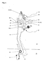
- a toggle lever unit 35 in the form of a Eccentric drive arranged in the region of the hand crank bearing axis 31; being the respective Toggle lever unit 35 has a toggle lever housing 36 which with the hand crank 33 of the Handle 30 and. rigidly connected to the hand crank bearing axis and with a handle part 34 the hand crank can be swiveled (see Fig. 5).
- an unlocking / locking lever 40 arranged, as shown in Fig.5, with its first End 41 in the region of the hand crank bearing axis 31 in the toggle lever housing 36 is mounted eccentrically and by means of the pivotable by the hand crank Toggle housing in pivoting movement for locking and unlocking (dashed Representation of the unlocking / locking lever) of the upper housing part 1 and in a lifting movement for pressing / separating the housing parts 1; 2 and the rollers 11; 21 is displaceable.
- each toggle lever housing 36 of the two toggle lever units 35 has, as in FIG. 5 shown, on the one hand for the first end 41 of the unlocking / locking lever 40 parallel to the axis, radially spaced from the bearing axis 31 of the crank handle 33, for Bearing axis end of the crank handle axially offset or protruding bearing 37 in the form of a journal 37, and on the other hand a V-shaped recess 38 on Toggle lever housing with two leg surfaces 38.1; 38.2 for generation, management and Limitation of the radial lifting and swiveling movement of the unlocking / locking lever parallel to the outside of the side wall 15; 16 of the upper housing part.
- the Bearings 31; 37 of the unlocking / locking lever 40 and the hand crank 33 are here arranged within the area of the V-shaped recess 38, and the V-shaped The recess is for the axial guidance and securing of the position on the journal 37 Swivel-mounted unlocking / locking lever with a screwed cover provided (see Fig. 1 to 4).
- Each of the two unlocking / locking levers 40 is in the form of a at its second end 42 formed essentially L-shaped hook 42, which in the locking position unlocking / locking lever (see Fig. 1, 3; 5), the outside / inside a side wall 25; 26 of the lower housing part 2 rigidly attached Locking bolt 49 on the bearing 37 of the unlocking / locking lever partially wrapped around and pressed against him, the upper Housing part 1 against the lower housing part 2 and the heating roller 11 against the Pressure roller 21 are pressed.
- a contact pressure in the locked state of the fuser between the hook 42 of the locking lever 40 and the locking bolt 49 and thus between the housing parts 1; 2 as tolerance compensation on each side of the Fixing unit in the area of the side walls 15; 16, a spring element 51 between each two housing parts 1; 2 arranged by means of the locking process and in locked state of the housing parts a contact pressure in the direction along the stroke direction and longitudinal axis of the unlocking / locking lever 40 can be generated, and by means of which the hook 42 of the unlocking / locking lever can be pressed onto the locking bolt 49.
- the Contact pressure is during the locking process by a semicircular Pivotal movement of the toggle lever housing 36 of the toggle lever unit 35 can be generated in the the bearing or the bearing pin 37 of the in the toggle lever housing eccentrically stored unlocking / locking lever 40 over a dead center of their trajectory is movable against the spring force of the spring element 51.
- the spring force of the two Spring elements 51 act on a contact pressure of the fixing rollers of a not shown usual fixing roller pressure unit counter. Both spring elements 51 are as Leaf springs attached to two on side walls 15; 16; 25; 26 of the housing parts 1; 2 Supports 12; 22 arranged between the upper and the lower housing part.
- Each of the unlocking / locking levers 40 engages on the side walls 15; 16 arranged spring means 47, by means of which the unlocking / locking lever with its Hook 42 in the direction of and against the locking bolt 49 and parallel to one Side wall level, the respective outside or inside of the side walls 15; 16; 25; 26 of the Housing parts 1; 2 is pivotable.
- the spring means 47 has one on one Sliding push rod arranged, pre-tensioned coil spring, which with one end against a bearing bush attached to the side wall 15; 16 Push rod supports and with its other end on one with the unlocking / locking lever 40 attached fastener is present.
- the pivotable handle 30 and thus the hand crank 33 lockable, on the one hand in a first horizontal position P1, in which the upper Housing part 1 is in its locked closed position CC, and on the other hand in a second vertical position P2, in which the upper housing part and thus the unlocking / locking lever 40 is unlocked (see Fig. 5, dashed line) so that upper housing part 1 by means of the handle by an angle of greater than or equal to 90 degrees its vertical open position CO is pivotable.
- the handle 30 points centrally in its handle part 34, as in FIG. 4 shown, a spring-loaded cylindrical locking pin 32 on the by means of the handle part against the spring force of a coil spring axially along it Center axis, or that of the handle part and parallel to the bearing axis 31 of the crank handle 33 into and out of locking bores 17; 18 of the side wall 15 of the upper housing part 1 is movable.
- crank handle 33 of the handle 30 in particular on both toggle lever housings also a spring rocker 39 (or rocker arm) arranged (see Fig. 1, 3-5), by means of the spring force acting on the crank handle the manual pivoting of the Hand crank or the handle part 34 in the first P1 and in the second position P2 is supportable.
- the spring rocker has one on a slidable Push rod arranged, pre-tensioned coil spring, which is at one end against a pivotable bearing bush attached to an inside of the side wall 15; 16 supports for the push rod and with its other end at one with the crank handle 33 fastened through a slot-shaped wall opening in the side wall pivotable connecting element is present.
- the course of the wall opening corresponds thereby the quarter-circular course of the hand crank, so that by half Distance of the wall opening arranged bearing bush at half the pivoting distance the hand crank the greatest spring force is generated and thus the hand crank from there can be pressed into the first P1 or second P2 position by means of the spring rocker.
- the device works as follows:
- the handle part 34 is together against a spring force of the spring rocker 39 with the crank handle 33 of the handle 30, taking the two toggle lever units 35 counterclockwise around the central axis of the bearing axis 31 of the hand crank in Direction of the second locking position P2 and the second locking bore 18 panned.
- the crank handle 33 and the bearing shaft 31 become rigid connected toggle lever housing 36 with its V-shaped recesses 38 or Guide calottes and the bearing points or journals 37 arranged therein and the in each case rotatably mounted unlocking / locking levers 40 about the central axis of the Hand crank bearing axis 31 in a circular arc counterclockwise panned.
- the journal 37 which are arranged eccentrically to the bearing axis 31, during the circular arc pivoting movement, as shown in Fig. 5, first from a right side of the central axis of the bearing axis 31 lower starting point to a center lying upper reversal point or dead center.
- the journals 37 move the Unlocking / locking lever 40, on the one hand, from second ones resting against them on the right-hand side Leg surfaces / side walls 38.2 of the V-shaped recesses / guide spheres 38 away and on the other hand press the unlocking / locking lever 40 with their L-shaped hooks 42 in the direction along its longitudinal axis and with increasing force against the Locking bolt 49, the upper housing part / chassis 1 against the spring force of the Disc springs 51 on the supports / support bearings 22 of the lower housing part / chassis 2 pulled down (by about 0.2mm).
- the on the handle 30 by the operator The operating force to be applied is reduced by the lever transmission ratio.
- the pivot pins 37 pivot Toggle housing 36 in a circular arc over an angle of e.g. about 60 degrees to one lower left of the center axis of the hand crank bearing axis 31 End point, wherein the locking lever 40 is initially rectilinear along its longitudinal axis down and with their hooks 42 in a lifting motion away from the Locking bolts 49 are moved.
- This has the advantage of locking between the upper and lower housing part / chassis 1; 2 even with one Several sheets between the pair of fuser rollers created a relatively small paper jam Force can be released by the operator.
- the unlocking / locking lever 40 by means of the continued pivoting movement of the left-hand side first, inner leg surfaces / side surfaces 38.1 of the V-shaped recesses / Guide caps 38 of the toggle housing 36 in a rectified Pivotal movement offset about the journal 37, so that the hook 42 of the unlocking / locking lever 40 from the area of the locking bolts 49 into a Unlocking position to release the upper housing part / chassis 1 can be moved.
- the pivoting movement of the unlocking / locking lever 40 takes place while overcoming the spring force of the spring means acting on the unlocking / locking levers / Coil springs 47 in a counterclockwise direction.
- the upper housing part 1 With its components by means of the handle part 34 by hand in a clockwise direction from the closed position CC to the open position CO by the Swivel axis 20 pivoted upward around the inside of the fuser unit is freely accessible for service purposes (see Fig. 2).
- the upper housing part is then by means of another conventional locking means (not shown) in its open position secured.
Landscapes
- Physics & Mathematics (AREA)
- General Physics & Mathematics (AREA)
- Electrophotography Configuration And Component (AREA)
- Fixing For Electrophotography (AREA)
- Sheets, Magazines, And Separation Thereof (AREA)
- Manual Feeding Of Sheets (AREA)
- Feeding And Guiding Record Carriers (AREA)
- Casings For Electric Apparatus (AREA)
- Lock And Its Accessories (AREA)
Abstract
Description
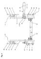
- Fig. 1
- die erfindungsgemäße Vorrichtung an einer aus einem Vervielfältigungsgerät herausgezogenen, geschlossenen Geräteeinheit in einer räumlichen Darstellung,
- Fig. 2
- die erfindungsgemäße Vorrichtung an einer aus einem Vervielfältigungsgerät herausgezogenen, offenen Geräteeinheit in einer räumlichen Darstellung,
- Fig. 3
- die erfindungsgemäße Vorrichtung nach Fig. 1 und 2 in einer vergrößerten räumlichen Darstellung unter Weglassung aller für die Vorrichtung nicht relevanten Teile der Geräteeinheit,
- Fig. 4
- die erfindungsgemäße Vorrichtung nach Fig. 3, in einer Draufsicht,
- Fig. 5
- die erfindungsgemäße Vorrichtung nach Fig. 3 als vergrößerte Teilansicht in einer Seitenansicht.
Fig. 1 bis Fig. 5 zeigen, dass die Mittel zum Verschwenken 3, Ent-/Verriegeln 4 und Trennen/Aneinanderpressen 5 eine gemeinsame Betätigungseinheit im Bereich des der Schwenkachse 20 gegenüberliegenden freien Endes der Gehäuseteile 1;2 aufweisen, derart, dass das Ent-/Verriegeln, Verschwenken und Trennen/Anpressen des oberen Gehäuseteils 1 gemeinsam und einhändig mittels der Betätigungseinheit in einem einzigen Bewegungsablauf durchführbar ist. Die Betätigungseinheit weist dabei am oberen Gehäuseteil 1 einen Handgriff 30 auf, und auf jeder Seite des oberen Gehäuseteils eine Kniehebeleinheit 35 und einen schwenk- und hubbeweglichen Ent-/Verriegelungshebel 40 mit auf einen zugeordneten Verriegelungsbolzen 49 jeder Seite des unteren Gehäuseteils 2 einwirkenden Haken 42 auf; und stehen der Handgriff, die Kniehebeleinheit und der Ent-/Verriegelungshebel miteinander in kraft- und formschlüssiger Wirkverbindung, derart, dass mittels des Handgriffes 30 sowohl die Kniehebeleinheit 35 und damit der Ent-/Verriegelungshebel 40 betätigbar, wie auch das obere Gehäuseteil 1 schwenkbar sind.
Claims (16)
- Vorrichtung zum manuellen Öffnen und Schließen eines Gerätegehäuses eines drucktechnischen Gerätes mit:dadurch gekennzeichnet,einem ersten (1) und einem zweiten (2) Gehäuseteil, die mittels einer Schwenkachse (20) verbunden sind und deren eines Gehäuseteil verschwenkbar angeordnet ist; rotierenden Fördermitteln (11;21) in mindestens einer Paar-Anordnung zum Hindurchführen und Fördern eines Bogens (S), die an einem der Schwenkachse gegenüberliegenden Ende der beiden Gehäuseteile in einer aneinander anliegenden achsparallelen Anordnung und in achsparallelen Ausrichtung zur Schwenkachse angeordnet sind, wobei eines der rotierenden Fördermittel im ersten Gehäuseteil und das andere im zweiten Gehäuseteil drehbar, antreibbar angeordnet sind;Mitteln zum Verschwenken (3) des ersten Gehäuseteils um die Schwenkachse herum von einer am zweiten Gehäuseteil anliegenden Schließstellung (CC) zu einer vom zweiten Gehäuseteil entfernten, das Geräteinnere freigebenden Offenstellung (CO) und zurück;Mitteln zum Ent-/Verriegeln (4) des in Schließstellung befindlichen ersten Gehäuseteils von/mit dem zweiten Gehäuseteil; undMitteln zum radialen Trennen/Aneinanderpressen (5) der rotierenden Fördermittel bei entriegelten bzw. verriegelten Gehäuseteilen;
dass die Mittel zum Verschwenken (3), Ent-/Verriegeln (4) und Trennen /Aneinanderpressen (5) eine gemeinsame Betätigungseinheit im Bereich des der Schwenkachse (20) gegenüberliegenden freien Endes der Gehäuseteile (1;2) aufweisen, derart, dass das Ent-/Verriegeln, Verschwenken und Trennen/Anpressen des ersten Gehäuseteils (1) gemeinsam und einhändig mittels der Betätigungseinheit in einem einzigen Bewegungsablauf durchführbar ist. - Vorrichtung nach Anspruch 1,
dadurch gekennzeichnet,
dass die Betätigungseinheit am ersten Gehäuseteil (1) mindestens einen Handgriff (30), eine Kniehebeleinheit (35) und einen schwenk- und hubbeweglichen Ent-/Verriegelungshebel (40) mit auf einen Verriegelungsbolzen (49) des zweiten Gehäuseteils (2) einwirkenden Haken (42) aufweist; und dass der Handgriff, die Kniehebeleinheit und der Ent-/Verriegelungshebel miteinander in kraft- und formschlüssiger Wirkverbindung stehen, derart, dass mittels des Handgriffes sowohl die Kniehebeleinheit und damit der Ent-/Verriegelungshebel betätigbar, wie auch das erste Gehäuseteil verschwenkbar sind. - Vorrichtung nach Anspruch 2,
dadurch gekennzeichnet,dass der Handgriff (30) in Form einer Handkurbel (33) ausgeführt ist und manuell um eine zur Schwenkachse (20) der Gehäuseteile achsparallelen Lagerachse (31) der Handkurbel hin und her schwenkbar ist;die Kniehebeleinheit (35) in Form eines Exzentertriebes im Bereich der Handkurbel-Lagerachse (31) angeordnet ist;die Kniehebeleinheit (35) ein Kniehebelgehäuse (36) aufweist, das mit der Handkurbel (33) des Handgriffs (30) starr verbunden und mit dieser schwenkbar ist; und der Ent-/Verriegelungshebel (40) mit seinem ersten Ende (41) im Bereich der Handkurbel-Lagerachse (31) in dem Kniehebelgehäuse (36) exzentrisch gelagert ist und mittels des durch die Handkurbel schwenkbaren Kniehebelgehäuses in Schwenkbewegung zum Ent-/Verriegeln des ersten Gehäuseteils (1) und in Hubbewegung zum Aneinanderpressen/Trennen der Gehäuseteile und der rotierenden Fördermittel (11;21) versetzbar ist. - Vorrichtung nach Anspruch 1,
dadurch gekennzeichnet,
dass die Betätigungseinheit folgendes aufweist:einen Handgriff (30) zum Verschwenken des ersten Gehäuseteils (1) in Form einer Handkurbel (33), mittels der er manuell um eine zur Schwenkachse (20) der Gehäuseteile (1;2) achsparallelen Lagerachse (31) der Handkurbel hin und her schwenkbar ist,eine in Form eines Exzentertriebes ausgeführte Kniehebeleinheit (35), die im Bereich der Handkurbel-Lagerachse (31) angeordnet ist;ein Kniehebelgehäuse (36) als Teil der Kniehebeleinheit (35) angeordnet, das mit der Handkurbel (33) des Handgriffs (30) starr verbunden und mit dieser schwenkbar ist, undein Ent-/Verriegelungshebel (40), der mit seinem ersten Ende (4) im Bereich der Handkurbel-Lagerachse (31) in dem Kniehebelgehäuse (36) exzentrisch gelagert ist und der mittels des durch die Handkurbel schwenkbaren Kniehebelgehäuses in eine Schwenkbewegung zum Ent-/Verriegeln des ersten Gehäuseteils (1) und in eine Hubbewegung zum Aneinanderpressen/Trennen der Gehäuseteile und der rotierenden Fördermittel (11;21) versetzbar ist. - Vorrichtung nach Anspruch 3 oder 4,
dadurch gekennzeichnet,
dass der schwenkbare Handgriff (30) und damit die Handkurbel (33) arretierbar ist, einerseits in einer ersten Position (P1), bei der das erste Gehäuseteil (1) sich in seiner verriegelten Schließstellung (CC) befindet, und andererseits in einer zweiten Position (P2), bei der das erste Gehäuseteil und damit der Ent-/Verriegelungshebel (40) entriegelt ist, derart, dass das erste Gehäuseteil mittels des Handgriffes in seine Offenstellung (CO) verschwenkbar ist. - Vorrichtung nach Anspruch 5,
dadurch gekennzeichnet,
dass der Handgriff (30) einen mit Federkraft beaufschlagten Arretierstift (32) aufweist, der mittels des Handgriffes axial und entlang einer Mittenachse des Handgriffes sowie parallel zur Lagerachse (31) der Handkurbel (33) in und aus Arretierbohrungen (17;18) einer Seitenwand (15;16) des ersten Gehäuseteils bewegbar ist. - Vorrichtung nach Anspruch 3 oder 4,
dadurch gekennzeichnet,
dass das Kniehebelgehäuse (36) der Kniehebeleinheit (35) für das erste Ende (41) des Ent-/Verriegelungshebels (40) eine achsenparallel, radial zur Lagerachse (31) der Handkurbel beabstandete, zum Lagerachsenende der Handkurbel axial nach außen versetzte Lagerstelle (37) und eine V-förmige Ausnehmung (38) mit Schenkelflächen (38.1; 38.2) zur Erzeugung, Führung und Begrenzung der Hub- und Schwenkbewegung des Ent-/Verriegelungshebels aufweist, wobei die Lagerstellen (31;37) des Ent-/Verriegelungshebels und der Handkurbel innerhalb des Bereiches der V-förmigen Ausnehmung angeordnet sind. - Vorrichtung nach Anspruch 7,
dadurch gekennzeichnet,
dass, bezogen auf die Position der Handkurbel-Lagerachse (31), ein radiales Abstandsverhältnis bzw. Hebelverhältnis der Ent-/Verriegelungshebel-Lagerstelle (37) zum Handgriff (30) vorgesehen ist, das vorbestimmten Bedienungskräften der Betätigungseinheit angepaßt ist. - Vorrichtung nach Anspruch 7,
dadurch gekennzeichnet,
dass der Ent-/Verriegelungshebel (40) an seinem zweiten Ende (42) in Form eines im wesentlichen L-förmigen Hakens (42) ausgebildet ist, der bei in Verriegelungsstellung befindlichem Ent-/Verriegelungshebel den am zweiten Gehäuseteil (2) starr angebrachten Verriegelungsbolzen (49) an seiner der Lagerstelle (37) des Ent-/Verriegelungshebels abgewandten Seite teilweise umschlingt und gegen ihn gepreßt wird, wobei das erste Gehäuseteil (1) gegen das zweite Gehäuseteil (2) und das erste rotierenden Fördermittel (11) gegen das zweite rotierenden Fördermittel (21) gepreßt werden. - Vorrichtung nach Anspruch 9,
dadurch gekennzeichnet,
dass an dem Ent-/Verriegelungshebel (40) ein Federmittel (47) angreift, mittels dem der Ent-/Verriegelungshebel mit seinem Haken (42) in Richtung zum Verriegelungsbolzen (49) und parallel zu einer Seitenwandebene (15;16;25;26) der Gehäuseteile verschwenkbar ist. - Vorrichtung nach Anspruch 2 oder 9,
dadurch gekennzeichnet,
dass mindestens ein Federelement (51) zwischen den beiden Gehäuseteilen (1;2) angeordnet ist, mittels dem beim Verriegelungsvorgang und im verriegelten Zustand der Gehäuseteile eine Anpreßkraft in Richtung längs der Hubrichtung und Längsachse des Ent-/Verriegelungshebels (40) erzeugbar ist und mittels der der Haken (42) des Ent-/Verriegelungshebels an den Verriegelungsbolzen (49) anpreßbar ist; und dass beim Verriegelungsvorgang durch eine halbkreisförmige Schwenkbewegung der Kniehebeleinheit (35), die Lagerstelle (37) des in der Kniehebeleinheit exzentrisch gelagerten Ent-/Verriegelungshebels über einen Totpunkt ihrer Bewegungsbahn hinweg gegen die Federkraft des Federelements (51) zum Erzeugen der Anpreßkraft bewegbar ist. - Vorrichtung nach Anspruch 11,
dadurch gekennzeichnet,
dass zwei Federelemente (51) als Blattfedern an zwei an Seitenwänden (15;16;25;26) der Gehäuseteile (1;2) angebrachten Abstützungen (12;22) zwischen dem oberen und dem unteren Gehäuseteil angeordnet sind. - Vorrichtung nach Anspruch 9,
dadurch gekennzeichnet,
dass die Verriegelungsstellung des Ent-/Verriegelungshebels (40) mittels eines Sensors (48) erfaßbar ist. - Vorrichtung nach Anspruch 5,
dadurch gekennzeichnet,
dass an der Handkurbel des Handgriffs (30) eine Federschwinge (39) angreift, mittels deren Federkraft das manuelle Verschwenken der Handkurbel mit dem Handgriff in die erste (P1) und zweite Position (P2) unterstützbar ist. - Vorrichtung nach Anspruch 1,
dadurch gekennzeichnet,
dass auf der Schwenkachse (20) in konzentrischer Anordnung zwei axial beabstandete Torsionsfedem (23;24) in Form von Schraubenfedern mit entgegengesetztem Wickelsinn und Wirkungsrichtung angeordnet sind, die mit ihrem ersten Ende mit dem ersten Gehäuseteil (1) und mit ihrem zweiten Ende mit dem zweiten Gehäuseteil (2) verbunden sind, derart, dass beim Verschwenken des ersten Gehäuseteils in die Offenstellung (CO) die erste Torsionsfeder (23) und beim Verschwenken in die Schließstellung (CC) die zweite Torsionsfeder (24) mit ihren Torsionsfederkräften die Schwenkbewegung anfänglich unterstützt und kurz vor Erreichen deren jeweiligen Endstellung dann das erste Gehäuseteil (1) abbremst. - Vorrichtung nach den Ansprüchen 1 bis 15,
dadurch gekennzeichnet,dass das Gerätegehäuse eine als Fixiereinheit ausgebildete Geräteeinheit zum Fixieren eines tonerbildtragenden, blattförmigen oder bandförmigen Aufzeichnungsmediums (S) in Form von Papier ode Folie darstellt;das erste Gehäuseteil (1) ein oberes, und das zweite ein unteres Gehäuseteil (2) der Fixiereinheit darstellt;das obere Gehäuseteil längs einer horizontal verlaufenden Transportbahn (T) für tonerbildtragenden Blätter (S) oder eines Bandes (S) um einen Winkel von größer 90 Grad nach oben schwenkbar ist; unddie rotierenden Fördermittel (11;21) als Fixierwalzen mit einer Heizwalze (11) und einer Anpreßwalze (21), als Fixierbänder mit einem Heizband und einem Anpreßband oder als Blatt-/Band-Transportwalzen/bänder ausgebildet sind, die in einer Paar-Anordnung senkrecht übereinanderliegend, mit ihren Drehachsen rechtwinklig zur Blatt-/Band-Transportbahn (T) in den beiden Gehäuseteilen angeordnet sind.
Applications Claiming Priority (2)
| Application Number | Priority Date | Filing Date | Title |
|---|---|---|---|
| DE10008910A DE10008910A1 (de) | 2000-02-25 | 2000-02-25 | Vorrichtung zum manuellen Öffnen und Schließen eines Gerätegehäuses |
| DE10008910 | 2000-02-25 |
Publications (3)
| Publication Number | Publication Date |
|---|---|
| EP1128235A2 true EP1128235A2 (de) | 2001-08-29 |
| EP1128235A3 EP1128235A3 (de) | 2004-12-15 |
| EP1128235B1 EP1128235B1 (de) | 2008-03-05 |
Family
ID=7632408
Family Applications (1)
| Application Number | Title | Priority Date | Filing Date |
|---|---|---|---|
| EP01101675A Expired - Lifetime EP1128235B1 (de) | 2000-02-25 | 2001-01-30 | Vorrichtung zum manuellen Öffnen und Schliessen eines Gerätegehäuses |
Country Status (4)
| Country | Link |
|---|---|
| US (1) | US20020020958A1 (de) |
| EP (1) | EP1128235B1 (de) |
| AT (1) | ATE388427T1 (de) |
| DE (2) | DE10008910A1 (de) |
Family Cites Families (5)
| Publication number | Priority date | Publication date | Assignee | Title |
|---|---|---|---|---|
| JPS55153975A (en) * | 1979-05-17 | 1980-12-01 | Canon Inc | Picture image forming device |
| DE3153660C2 (de) * | 1980-05-16 | 1993-05-19 | Canon Kk | Bildaufzeichnungsger{t |
| JPS58160971A (ja) * | 1982-03-18 | 1983-09-24 | Sanyo Electric Co Ltd | 定着装置 |
| JPS6091377A (ja) * | 1983-10-25 | 1985-05-22 | Canon Inc | 画像形成装置 |
| US5940669A (en) * | 1997-07-03 | 1999-08-17 | Output Technology Corporation | Printer |
-
2000
- 2000-02-25 DE DE10008910A patent/DE10008910A1/de not_active Withdrawn
-
2001
- 2001-01-30 EP EP01101675A patent/EP1128235B1/de not_active Expired - Lifetime
- 2001-01-30 AT AT01101675T patent/ATE388427T1/de not_active IP Right Cessation
- 2001-01-30 DE DE50113677T patent/DE50113677D1/de not_active Expired - Lifetime
- 2001-02-23 US US09/792,736 patent/US20020020958A1/en not_active Abandoned
Also Published As
| Publication number | Publication date |
|---|---|
| EP1128235B1 (de) | 2008-03-05 |
| EP1128235A3 (de) | 2004-12-15 |
| DE50113677D1 (de) | 2008-04-17 |
| DE10008910A1 (de) | 2001-08-30 |
| US20020020958A1 (en) | 2002-02-21 |
| ATE388427T1 (de) | 2008-03-15 |
Similar Documents
| Publication | Publication Date | Title |
|---|---|---|
| DE60129262T2 (de) | Schaltermechanismus mit vereinfachter Ausbildung | |
| DE60002145T2 (de) | Drucker | |
| DE3439132C2 (de) | ||
| DE4315909C2 (de) | Vorrichtung zum Abstützen von Druckzylindern in einer Rotationsdruckmaschine | |
| EP0182080A2 (de) | Sicherheitseinrichtung an Bogenrotationsdruckmaschinen | |
| DE2133693A1 (de) | Bogenrotations-druckmaschine | |
| DE19543152A1 (de) | Vorrichtung zum Falten von Blättern | |
| DE69006613T2 (de) | Anordnung und Verfahren zum Zusammenbau von Aufzeichnungseinheiten in einem elektrophotographischen Aufzeichnungsgerät. | |
| EP0960032B1 (de) | Belegtransport- und anschlageinrichtung | |
| DE3522926A1 (de) | Kopiergeraet | |
| DE68914889T2 (de) | Thermodruckverfahren. | |
| DE2945840C2 (de) | Vorrichtung zur Zuführung des obersten Blattes von einem Blattstapel für ein Kopiergerät | |
| EP1099549B1 (de) | Vorrichtung und Verfahren zum Stützen von fliegend gelagerten Zylindern | |
| EP0714768B1 (de) | Druckwerksschaltung | |
| EP0683043A1 (de) | Druckwerkszylinder einer Rollenrotationsdruckmaschine | |
| EP1452301A2 (de) | Kniehebelpresse | |
| DE1815850C3 (de) | Vorrichtung in oder an einem Kopiergerät mit räumlich getrennten Zuführtischen für Kopierpapier und Original K.K. Ricoh, Tokio | |
| EP1128235B1 (de) | Vorrichtung zum manuellen Öffnen und Schliessen eines Gerätegehäuses | |
| DE19602568C2 (de) | Vorrichtung zum Druckan-/ und -abstellen eines Zylinders | |
| EP0463997B1 (de) | Kassette zum Aufwickeln von fotografischem Bandmaterial | |
| DD261576A5 (de) | Einrichtung zur entnahme von bedruckten bogen aus dem ausleger einer bogenrotationsdruckmaschine | |
| DE3038370A1 (de) | Vorlagen-niederhaltevorrichtung | |
| EP0096246A2 (de) | Kupplungsvorrichtung für ein Stellrad | |
| EP0332264A2 (de) | Büromaschine, z. B. Drucker | |
| EP1930271B1 (de) | Vorrichtung zum Erzeugen dreifach gefalteter Papierstreifen in einem Durchlauf |
Legal Events
| Date | Code | Title | Description |
|---|---|---|---|
| PUAI | Public reference made under article 153(3) epc to a published international application that has entered the european phase |
Free format text: ORIGINAL CODE: 0009012 |
|
| AK | Designated contracting states |
Kind code of ref document: A2 Designated state(s): AT BE CH CY DE DK ES FI FR GB GR IE IT LI LU MC NL PT SE TR |
|
| AX | Request for extension of the european patent |
Free format text: AL;LT;LV;MK;RO;SI |
|
| PUAL | Search report despatched |
Free format text: ORIGINAL CODE: 0009013 |
|
| RAP1 | Party data changed (applicant data changed or rights of an application transferred) |
Owner name: EASTMAN KODAK COMPANY |
|
| AK | Designated contracting states |
Kind code of ref document: A3 Designated state(s): AT BE CH CY DE DK ES FI FR GB GR IE IT LI LU MC NL PT SE TR |
|
| AX | Request for extension of the european patent |
Extension state: AL LT LV MK RO SI |
|
| 17P | Request for examination filed |
Effective date: 20050427 |
|
| AKX | Designation fees paid |
Designated state(s): AT BE CH CY DE DK ES FI FR GB GR IE IT LI LU MC NL PT SE TR |
|
| 17Q | First examination report despatched |
Effective date: 20060818 |
|
| GRAP | Despatch of communication of intention to grant a patent |
Free format text: ORIGINAL CODE: EPIDOSNIGR1 |
|
| RIN1 | Information on inventor provided before grant (corrected) |
Inventor name: STRAUB, TIMO Inventor name: KONDAY, ANDREAS Inventor name: DETTINGER, KARL-HEINZ Inventor name: WEBER, MARKUS |
|
| GRAS | Grant fee paid |
Free format text: ORIGINAL CODE: EPIDOSNIGR3 |
|
| GRAA | (expected) grant |
Free format text: ORIGINAL CODE: 0009210 |
|
| AK | Designated contracting states |
Kind code of ref document: B1 Designated state(s): AT BE CH CY DE DK ES FI FR GB GR IE IT LI LU MC NL PT SE TR |
|
| REG | Reference to a national code |
Ref country code: GB Ref legal event code: FG4D Free format text: NOT ENGLISH |
|
| REG | Reference to a national code |
Ref country code: CH Ref legal event code: EP |
|
| REG | Reference to a national code |
Ref country code: IE Ref legal event code: FG4D Free format text: LANGUAGE OF EP DOCUMENT: GERMAN |
|
| REF | Corresponds to: |
Ref document number: 50113677 Country of ref document: DE Date of ref document: 20080417 Kind code of ref document: P |
|
| PG25 | Lapsed in a contracting state [announced via postgrant information from national office to epo] |
Ref country code: ES Free format text: LAPSE BECAUSE OF FAILURE TO SUBMIT A TRANSLATION OF THE DESCRIPTION OR TO PAY THE FEE WITHIN THE PRESCRIBED TIME-LIMIT Effective date: 20080616 Ref country code: FI Free format text: LAPSE BECAUSE OF FAILURE TO SUBMIT A TRANSLATION OF THE DESCRIPTION OR TO PAY THE FEE WITHIN THE PRESCRIBED TIME-LIMIT Effective date: 20080305 |
|
| NLV1 | Nl: lapsed or annulled due to failure to fulfill the requirements of art. 29p and 29m of the patents act | ||
| REG | Reference to a national code |
Ref country code: IE Ref legal event code: FD4D |
|
| PG25 | Lapsed in a contracting state [announced via postgrant information from national office to epo] |
Ref country code: SE Free format text: LAPSE BECAUSE OF FAILURE TO SUBMIT A TRANSLATION OF THE DESCRIPTION OR TO PAY THE FEE WITHIN THE PRESCRIBED TIME-LIMIT Effective date: 20080605 Ref country code: NL Free format text: LAPSE BECAUSE OF FAILURE TO SUBMIT A TRANSLATION OF THE DESCRIPTION OR TO PAY THE FEE WITHIN THE PRESCRIBED TIME-LIMIT Effective date: 20080305 Ref country code: PT Free format text: LAPSE BECAUSE OF FAILURE TO SUBMIT A TRANSLATION OF THE DESCRIPTION OR TO PAY THE FEE WITHIN THE PRESCRIBED TIME-LIMIT Effective date: 20080805 |
|
| EN | Fr: translation not filed | ||
| PLBE | No opposition filed within time limit |
Free format text: ORIGINAL CODE: 0009261 |
|
| STAA | Information on the status of an ep patent application or granted ep patent |
Free format text: STATUS: NO OPPOSITION FILED WITHIN TIME LIMIT |
|
| PG25 | Lapsed in a contracting state [announced via postgrant information from national office to epo] |
Ref country code: IE Free format text: LAPSE BECAUSE OF FAILURE TO SUBMIT A TRANSLATION OF THE DESCRIPTION OR TO PAY THE FEE WITHIN THE PRESCRIBED TIME-LIMIT Effective date: 20080305 Ref country code: DK Free format text: LAPSE BECAUSE OF FAILURE TO SUBMIT A TRANSLATION OF THE DESCRIPTION OR TO PAY THE FEE WITHIN THE PRESCRIBED TIME-LIMIT Effective date: 20080305 |
|
| 26N | No opposition filed |
Effective date: 20081208 |
|
| PG25 | Lapsed in a contracting state [announced via postgrant information from national office to epo] |
Ref country code: FR Free format text: LAPSE BECAUSE OF FAILURE TO SUBMIT A TRANSLATION OF THE DESCRIPTION OR TO PAY THE FEE WITHIN THE PRESCRIBED TIME-LIMIT Effective date: 20081226 |
|
| PG25 | Lapsed in a contracting state [announced via postgrant information from national office to epo] |
Ref country code: IT Free format text: LAPSE BECAUSE OF FAILURE TO SUBMIT A TRANSLATION OF THE DESCRIPTION OR TO PAY THE FEE WITHIN THE PRESCRIBED TIME-LIMIT Effective date: 20080305 Ref country code: MC Free format text: LAPSE BECAUSE OF NON-PAYMENT OF DUE FEES Effective date: 20090131 |
|
| REG | Reference to a national code |
Ref country code: CH Ref legal event code: PL |
|
| GBPC | Gb: european patent ceased through non-payment of renewal fee |
Effective date: 20090130 |
|
| PG25 | Lapsed in a contracting state [announced via postgrant information from national office to epo] |
Ref country code: CY Free format text: LAPSE BECAUSE OF FAILURE TO SUBMIT A TRANSLATION OF THE DESCRIPTION OR TO PAY THE FEE WITHIN THE PRESCRIBED TIME-LIMIT Effective date: 20080305 |
|
| PG25 | Lapsed in a contracting state [announced via postgrant information from national office to epo] |
Ref country code: CH Free format text: LAPSE BECAUSE OF NON-PAYMENT OF DUE FEES Effective date: 20090131 Ref country code: LI Free format text: LAPSE BECAUSE OF NON-PAYMENT OF DUE FEES Effective date: 20090131 |
|
| PG25 | Lapsed in a contracting state [announced via postgrant information from national office to epo] |
Ref country code: GB Free format text: LAPSE BECAUSE OF NON-PAYMENT OF DUE FEES Effective date: 20090130 |
|
| PG25 | Lapsed in a contracting state [announced via postgrant information from national office to epo] |
Ref country code: BE Free format text: LAPSE BECAUSE OF NON-PAYMENT OF DUE FEES Effective date: 20090131 |
|
| PG25 | Lapsed in a contracting state [announced via postgrant information from national office to epo] |
Ref country code: AT Free format text: LAPSE BECAUSE OF NON-PAYMENT OF DUE FEES Effective date: 20090130 |
|
| PG25 | Lapsed in a contracting state [announced via postgrant information from national office to epo] |
Ref country code: GR Free format text: LAPSE BECAUSE OF FAILURE TO SUBMIT A TRANSLATION OF THE DESCRIPTION OR TO PAY THE FEE WITHIN THE PRESCRIBED TIME-LIMIT Effective date: 20080606 |
|
| PG25 | Lapsed in a contracting state [announced via postgrant information from national office to epo] |
Ref country code: LU Free format text: LAPSE BECAUSE OF NON-PAYMENT OF DUE FEES Effective date: 20090130 |
|
| PG25 | Lapsed in a contracting state [announced via postgrant information from national office to epo] |
Ref country code: TR Free format text: LAPSE BECAUSE OF FAILURE TO SUBMIT A TRANSLATION OF THE DESCRIPTION OR TO PAY THE FEE WITHIN THE PRESCRIBED TIME-LIMIT Effective date: 20080305 |
|
| PGFP | Annual fee paid to national office [announced via postgrant information from national office to epo] |
Ref country code: DE Payment date: 20120131 Year of fee payment: 12 |
|
| PG25 | Lapsed in a contracting state [announced via postgrant information from national office to epo] |
Ref country code: DE Free format text: LAPSE BECAUSE OF NON-PAYMENT OF DUE FEES Effective date: 20130801 |
|
| REG | Reference to a national code |
Ref country code: DE Ref legal event code: R119 Ref document number: 50113677 Country of ref document: DE Effective date: 20130801 |