EP1128101B1 - Seal assemblies - Google Patents
Seal assemblies Download PDFInfo
- Publication number
- EP1128101B1 EP1128101B1 EP01301483A EP01301483A EP1128101B1 EP 1128101 B1 EP1128101 B1 EP 1128101B1 EP 01301483 A EP01301483 A EP 01301483A EP 01301483 A EP01301483 A EP 01301483A EP 1128101 B1 EP1128101 B1 EP 1128101B1
- Authority
- EP
- European Patent Office
- Prior art keywords
- pressure
- reservoir
- gas
- seal
- intensifier
- Prior art date
- Legal status (The legal status is an assumption and is not a legal conclusion. Google has not performed a legal analysis and makes no representation as to the accuracy of the status listed.)
- Expired - Lifetime
Links
- 230000000712 assembly Effects 0.000 title description 10
- 238000000429 assembly Methods 0.000 title description 10
- 238000000034 method Methods 0.000 claims description 20
- 230000003068 static effect Effects 0.000 claims description 10
- 238000007789 sealing Methods 0.000 claims description 6
- 239000012530 fluid Substances 0.000 claims description 3
- 238000006073 displacement reaction Methods 0.000 claims description 2
- 239000007789 gas Substances 0.000 description 63
- 238000005086 pumping Methods 0.000 description 3
- IJGRMHOSHXDMSA-UHFFFAOYSA-N Atomic nitrogen Chemical compound N#N IJGRMHOSHXDMSA-UHFFFAOYSA-N 0.000 description 2
- OKTJSMMVPCPJKN-UHFFFAOYSA-N Carbon Chemical group [C] OKTJSMMVPCPJKN-UHFFFAOYSA-N 0.000 description 1
- 230000004888 barrier function Effects 0.000 description 1
- 230000007257 malfunction Effects 0.000 description 1
- 229910052757 nitrogen Inorganic materials 0.000 description 1
- 238000007666 vacuum forming Methods 0.000 description 1
Images

Classifications
-
- F—MECHANICAL ENGINEERING; LIGHTING; HEATING; WEAPONS; BLASTING
- F04—POSITIVE - DISPLACEMENT MACHINES FOR LIQUIDS; PUMPS FOR LIQUIDS OR ELASTIC FLUIDS
- F04D—NON-POSITIVE-DISPLACEMENT PUMPS
- F04D29/00—Details, component parts, or accessories
- F04D29/08—Sealings
- F04D29/10—Shaft sealings
- F04D29/12—Shaft sealings using sealing-rings
- F04D29/122—Shaft sealings using sealing-rings especially adapted for elastic fluid pumps
- F04D29/124—Shaft sealings using sealing-rings especially adapted for elastic fluid pumps with special means for adducting cooling or sealing fluid
-
- F—MECHANICAL ENGINEERING; LIGHTING; HEATING; WEAPONS; BLASTING
- F01—MACHINES OR ENGINES IN GENERAL; ENGINE PLANTS IN GENERAL; STEAM ENGINES
- F01D—NON-POSITIVE DISPLACEMENT MACHINES OR ENGINES, e.g. STEAM TURBINES
- F01D11/00—Preventing or minimising internal leakage of working-fluid, e.g. between stages
- F01D11/02—Preventing or minimising internal leakage of working-fluid, e.g. between stages by non-contact sealings, e.g. of labyrinth type
- F01D11/04—Preventing or minimising internal leakage of working-fluid, e.g. between stages by non-contact sealings, e.g. of labyrinth type using sealing fluid, e.g. steam
- F01D11/06—Control thereof
-
- F—MECHANICAL ENGINEERING; LIGHTING; HEATING; WEAPONS; BLASTING
- F16—ENGINEERING ELEMENTS AND UNITS; GENERAL MEASURES FOR PRODUCING AND MAINTAINING EFFECTIVE FUNCTIONING OF MACHINES OR INSTALLATIONS; THERMAL INSULATION IN GENERAL
- F16J—PISTONS; CYLINDERS; SEALINGS
- F16J15/00—Sealings
- F16J15/002—Sealings comprising at least two sealings in succession
- F16J15/004—Sealings comprising at least two sealings in succession forming of recuperation chamber for the leaking fluid
-
- F—MECHANICAL ENGINEERING; LIGHTING; HEATING; WEAPONS; BLASTING
- F16—ENGINEERING ELEMENTS AND UNITS; GENERAL MEASURES FOR PRODUCING AND MAINTAINING EFFECTIVE FUNCTIONING OF MACHINES OR INSTALLATIONS; THERMAL INSULATION IN GENERAL
- F16J—PISTONS; CYLINDERS; SEALINGS
- F16J15/00—Sealings
- F16J15/16—Sealings between relatively-moving surfaces
- F16J15/34—Sealings between relatively-moving surfaces with slip-ring pressed against a more or less radial face on one member
- F16J15/3404—Sealings between relatively-moving surfaces with slip-ring pressed against a more or less radial face on one member and characterised by parts or details relating to lubrication, cooling or venting of the seal
-
- F—MECHANICAL ENGINEERING; LIGHTING; HEATING; WEAPONS; BLASTING
- F16—ENGINEERING ELEMENTS AND UNITS; GENERAL MEASURES FOR PRODUCING AND MAINTAINING EFFECTIVE FUNCTIONING OF MACHINES OR INSTALLATIONS; THERMAL INSULATION IN GENERAL
- F16J—PISTONS; CYLINDERS; SEALINGS
- F16J15/00—Sealings
- F16J15/16—Sealings between relatively-moving surfaces
- F16J15/40—Sealings between relatively-moving surfaces by means of fluid
Definitions
- the present invention relates to seal assemblies and in particular to seal assemblies utilising dry gas seals.
- US 4,005,580 discloses a labyrinth seal whereby a seal gas is used.
- seal assemblies for, for example, gas compressors
- seal assemblies on either side of the impellor shaft, to seal the compressor chamber on the suction and discharge side.
- Such seal assemblies typically include a pair of gas seals spaced axially of one another to define a chamber therebetween.
- Leakage across the inboard gas seal is collected in the chamber defined between the two gas seals and, hitherto, has been ducted away to a flare stack or atmospheric vent.
- Leakage under dynamic conditions is typically from 20 to 100 standard litres per minute, depending on the suction pressure of the compressor.
- the product gas may be contaminated, it is conventional practice to provide a supply of filtered product gas to the product side of the inboard seal.
- Product gas is supplied either from a higher pressure stage of the compressor or alternative supply and is fed through a filter system and delivered back to the product side of the inboard seal.
- the product sides of the inboard seals are run at suction pressure. The amount of filtered gas delivered to the seals is in excess of the amount of leakage across the seal, so that the excess filtered gas will flow into the compressor chamber, preventing unfiltered product gas therefrom, from coming into contact with the inboard seal.
- the present invention provides a system in which leaking across the inboard seal gas is recirculated, thereby avoiding the need to flare or vent the gas and the consequent loss.
- An additional benefit is the substantial reduction of emissions into the atmosphere.
- a method for sealing a pressurised gaseous product comprising providing a seal assembly having an inboard seal and an outboard seal spaced axially of the inboard seal to define a chamber therebetween, the inboard seal being a gas seal which is disposed between the sealed gaseous product and the chamber, an inlet opening to the side of the inboard seal exposed to the gaseous product, means being provided to supply clean gas to the inlet and an outlet from the chamber being connected to a reservoir, the resevoir being connected back to the inlet via a pressure intensifier, characterised in that under static conditions additional clean gas is delivered to the reservoir when pressure in the reservoir falls below a predetermined minimum value and, under dynamic conditions, the pressure intensifier maintains the pressure in the reservoir between predetermined limits.
- the present invention also provides for a sealing system in accordance with claim 19.
- the pressure intensifier is controlled to maintain the pressure in the reservoir between predetermined limits.
- the predetermined limits will be up to the flare stack back pressure, preferably from 5% to 95% or more preferably from 30% to 95% of the flare stack pressure.
- the upper predetermined limit is set by the spring load pressure of a non-return valve between the reservoir and atmospheric vent.
- Preferred limits will be from 5% to 95% or more preferably from 30% to 95% of the spring load pressure.
- the pressure intensifier is controlled to provide a flow rate at the inlet to the inboard side of the inboard seal in excess of leakage across the inboard seal, the additional clean gas required to do this, being delivered to the reservoir from a supply of clean gas.
- Additional clean gas is introduced into the reservoir to prevent a vacuum forming therein.
- both the inboard and outboard seals defining the leakage collection chamber are gas seals.
- other forms of seals may be used on the outboard side of the chamber, for example segmented carbon rings, close clearance bushes or labrynth seals.
- additional seals may be provided between the inboard seal and the product chamber.
- FIG. 1 illustrates diagrammatically a compressor 10 having a suction inlet 12 and a discharge outlet 14.
- An impellor 16 is mounted for rotation on a shaft 18 in bearings 20.
- Seal assemblies 22 are provided between the compressor housing and the bearings 20.
- Each seal assembly 22 comprises inner and outer gas seals 24,26 mounted in axially spaced relationship to define a chamber 28 therebetween.
- the gas seals 24,26 are of conventional design having a rotor 30 mounted for rotation with the shaft 18 and a stator 32 which is mounted for axial movement and sealed with respect to a housing 34.
- the stator 32 is urged axially into engagement with the rotor 30 by resilient means, not shown. Grooves are provided in the sealing face of either the rotor 30 or stator 32, these grooves acting to generate a cushion of gas between the rotor 30 and stator 32, when the shaft 18 rotates.
- leakage across the inboard seal 24 is typically of the order of 20 to 100 standard litres per minute, depending on the size, suction pressure and speed of the compressor 10.
- the resilient means forces the rotor 30 into engagement with the stator 32, reducing leakage across the inboard seal.
- leakage across the inboard seal 24 is typically of the order of 25% of the dynamic leakage.
- Product gas from the discharge outlet 14 of the compressor 10 or a stage of the compressor higher than suction is tapped off and delivered to a filter assembly 36, at point A.
- gas from an alternative supply may be delivered to point A.
- the filtered gas is then delivered to inlets 38 opening to the product side of the inboard seals 24. This filtered gas is delivered at a rate in excess of the leakage across the seals 24 so that excess filtered gas will be forced along the shaft 18 into the compressor chamber, preventing the unfiltered product gas which may be contaminated, from reaching the inboard seals 24.
- the product side of the inboard seal 24 on the discharge side of the compressor 10 is connected by line 40 to the suction inlet 12, so that, under dynamic conditions, the product side of the inboard seal 24 on both sides of the compressor 10, will run at suction pressure.
- the filtered gas which is at a pressure higher than the suction pressure, will consequently be delivered to the product sides of the seals 24 which are at the lower suction pressure.
- a reservoir 50 is connected to the line 52 between the chamber 28 and the flare stack 44 or atmospheric vent.
- a non-return valve 54 prevents flow of gas from the reservoir 50 towards chamber 28.
- a non-return valve 60 is provided between the connection to reservoir 50 and flare stack 44 or atmospheric vent, the non-return valve 60 remaining closed while pressure in line 52 is below flare stack pressure or a determined spring value of the non-return valve 60. While pressure in the line 52 remains below these values, gas leaking past the seal 24 will consequently be collected in the reservoir 50. Should the pressure in the line 52 rise above the flare stack pressure, or the non-return valve spring value, non-return valve 60 will open allowing the gas to escape into the flare stack 44 or atmospheric vent.
- a pressure safety valve 58 is provided on the reservoir 50, which will connect the reservoir 50 to the flare stack 44 or atmospheric vent, should pressure therein rise above a predetermined value, due to malfunction of the system, for example on failure of seal 24.
- a pressure intensifier 70 is connected to the reservoir 50, to pump gas therefrom.
- the pressure intensifier is preferably a single or two-stage booster pump, in which a piston is driven by either compressed nitrogen, air or pumped fluid from a source 72. Alternatively, other forms of positive displacement pump may be used, for example an electrically driven pump.
- the pressure intensifier 70 is controlled by a control unit 74.
- the pressure intensifier 70 delivers gas from the reservoir 50 via line 75 and non-return valve 76, back to the inlet 38, where it is recycled through the seal 24.
- the inlet to reservoir 50 is also connected to the line 78 downstream of the filter assembly 36, via a line 80.
- a non-return valve 82 downstream of line 80, prevents flow of gas from line 75 to line 80.
- Line 80 also includes a pressure control valve 84, which opens when pressure in the reservoir 50 falls below a predetermined value above vacuum of say 0.3 barg.
- Line 75 is also connected to the flare stack 44 or atmospheric vent by pressure release valve 86 and a non-return valve 88.
- filtered gas will be delivered to the product side of gas seals 24 by inlet 38, due to the pressure differential between the suction and discharge sides of the compressor 10, in conventional manner. Filtered gas leaking past the seals 24, rather than being burnt in the flare stack 44, or released into an atmospheric vent, will be collected in reservoir 50.
- the pressure intensifier 70 increases the pressure of the leakage gas from the reservoir 50 so that it may be returned to the inlet 38 and recycled.
- the pressure intensifier 70 is controlled by the control unit 74, to maintain the pressure in the reservoir 50 at between 30% and 95% of the flare stack pressure or non-return valve 60 spring load pressure on a vented system.
- pressure control valve 84 will remain closed so that no additional filtered gas will be delivered to the reservoir 50.
- Pressure indicator switches 90,92,94 are connected to the reservoir 50, indicator 90 indicating if pressure in the reservoir 50 is high, indicator 92 indicating if pressure in the reservoir 50 is low and indicator 94 indicating if the pressure in the reservoir 50 is very low.
- a solenoid valve 96 is automatically operated to close the supply of the motive fluid to the pressure intensifier and thereby to stop pumping from the reservoir 50 if the pressure in reservoir 50 is very low.
- This gas as well as that leaking past the seals 24, will then be pumped back to the inlet 38 by the pressure intensifier 70. In this manner, filtered gas is continuously recycled through the seals 24 and creates a clean gas barrier between the gas in the compressor chamber and the seals 24.
- the system described above would typically be capable of pressure intensification up to about 50 bar.
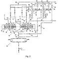
- multi-stage pressure intensification may be used, for example as illustrated in Figure 2.
- gas from the first reservoir 50 is compressed by pressure intensifier 70 in the manner disclosed above and is pumped to a second reservoir 50'.
- the second pressure intensifier 70' is controlled to maintain a pressure in the second reservoir 50' at a pre-set value (about 30 bar).
- the line 80 is connected to the inlet to the second reservoir 50' and the pressure control valve 84 opens when pressure in the second reservoir 50' falls below a pre-set value (about 20 bar).
- the gas in the second reservoir 50' may then be pumped by a pressure intensifier 70' at the required delivery pressure (up to about 100 bar) and delivered back to the inlet 38.
Landscapes
- Engineering & Computer Science (AREA)
- General Engineering & Computer Science (AREA)
- Mechanical Engineering (AREA)
- Sealing Devices (AREA)
- Sealing Using Fluids, Sealing Without Contact, And Removal Of Oil (AREA)
- Mechanical Sealing (AREA)
- Gas-Insulated Switchgears (AREA)
- Compressor (AREA)
- Structures Of Non-Positive Displacement Pumps (AREA)
- Control Of Positive-Displacement Pumps (AREA)
Applications Claiming Priority (2)
| Application Number | Priority Date | Filing Date | Title |
|---|---|---|---|
| GB0004239 | 2000-02-24 | ||
| GBGB0004239.0A GB0004239D0 (en) | 2000-02-24 | 2000-02-24 | Seal assemblies |
Publications (3)
| Publication Number | Publication Date |
|---|---|
| EP1128101A2 EP1128101A2 (en) | 2001-08-29 |
| EP1128101A3 EP1128101A3 (en) | 2003-07-02 |
| EP1128101B1 true EP1128101B1 (en) | 2005-10-12 |
Family
ID=9886226
Family Applications (1)
| Application Number | Title | Priority Date | Filing Date |
|---|---|---|---|
| EP01301483A Expired - Lifetime EP1128101B1 (en) | 2000-02-24 | 2001-02-20 | Seal assemblies |
Country Status (8)
| Country | Link |
|---|---|
| US (1) | US6708981B2 (enExample) |
| EP (1) | EP1128101B1 (enExample) |
| JP (1) | JP2001289192A (enExample) |
| CA (1) | CA2337925C (enExample) |
| DE (1) | DE60113894T2 (enExample) |
| GB (1) | GB0004239D0 (enExample) |
| NO (1) | NO331069B1 (enExample) |
| RU (1) | RU2285173C2 (enExample) |
Families Citing this family (31)
| Publication number | Priority date | Publication date | Assignee | Title |
|---|---|---|---|---|
| EP1350997B1 (en) * | 2002-04-05 | 2014-10-01 | Ebara Corporation | Method for operating a seal device |
| JP4218756B2 (ja) * | 2003-10-17 | 2009-02-04 | 株式会社荏原製作所 | 真空排気装置 |
| GB0402887D0 (en) * | 2004-02-10 | 2004-03-17 | Aesseal Plc | Applications for controlling liquid flow through a seal when using a forced circulation barrier fluid suppport system |
| EP1712816A1 (de) * | 2005-04-14 | 2006-10-18 | Siemens Aktiengesellschaft | Dichtungssystem zur Abdichtung eines Prozessgasraumes gegen einen Dichtraum |
| NO325900B1 (no) * | 2005-10-07 | 2008-08-11 | Aker Subsea As | Anordning og fremgangsmåte for regulering av tilførsel av barrieregass til en kompressormodul |
| JP4857766B2 (ja) * | 2005-12-28 | 2012-01-18 | 株式会社日立プラントテクノロジー | 遠心圧縮機およびそれに用いるドライガスシールシステム |
| US7544039B1 (en) | 2006-06-14 | 2009-06-09 | Florida Turbine Technologies, Inc. | Dual spool shaft with intershaft seal |
| US8511219B2 (en) * | 2007-03-28 | 2013-08-20 | Clyde Union Inc. | Zero emissions reciprocating pump |
| US7784395B2 (en) * | 2007-03-28 | 2010-08-31 | Clyde Union Inc. | Zero emissions reciprocating pump |
| EP2006584A1 (de) * | 2007-06-21 | 2008-12-24 | Siemens Aktiengesellschaft | Puffereinrichtung zum Abführen von Leckagegas zu einem Entsorgungssystem und Sperrgassystem |
| US20110209786A1 (en) * | 2008-11-12 | 2011-09-01 | Rasmussen Peter C | Vessel Compressor Methods and Systems |
| SG172127A1 (en) * | 2008-12-15 | 2011-07-28 | Flowserve Man Co | Seal leakage gas recovery system |
| US8061984B2 (en) | 2009-04-06 | 2011-11-22 | Dresser-Rand Company | Dry gas blow down seal |
| JP2011052620A (ja) * | 2009-09-03 | 2011-03-17 | Mitsubishi Heavy Industries Compressor Corp | ドライガスシールからのリークガス回収装置 |
| JP5548094B2 (ja) * | 2010-10-21 | 2014-07-16 | 株式会社神戸製鋼所 | 圧縮機 |
| JP5231611B2 (ja) * | 2010-10-22 | 2013-07-10 | 株式会社神戸製鋼所 | 圧縮機 |
| AU2010366070A1 (en) * | 2010-12-02 | 2013-06-27 | Abb Oy | Seal arrangement for a propeller shaft and method for sealing a propeller shaft |
| US20130064638A1 (en) * | 2011-09-08 | 2013-03-14 | Moorthi Subramaniyan | Boundary Layer Blowing Using Steam Seal Leakage Flow |
| ITCO20110057A1 (it) * | 2011-12-05 | 2013-06-06 | Nuovo Pignone Spa | Tenuta a gas secco per buffer ad alta pressione di pompa per co2 supercritico |
| EP2838789B1 (en) * | 2012-04-17 | 2016-05-18 | Wärtsilä Finland Oy | An arrangement for sealing a propeller shaft of a marine vessel and a method of controlling the operation thereof |
| BR112014031692A2 (pt) | 2012-06-18 | 2017-10-31 | Flowserve Man Co | intensificador para um sistema de fornecimento de gás de uma vedação mecânica. |
| GB2517132B (en) * | 2013-06-12 | 2015-11-11 | Aes Eng Ltd | Barrier System for Mechanical Seal |
| CA2962897C (en) | 2014-09-29 | 2019-08-06 | New Way Machine Components, Inc. | Porous media ventless seal |
| CN104806559B (zh) * | 2015-04-08 | 2017-10-03 | 中国神华能源股份有限公司 | 压缩机密封气的供应装置、气液分离系统及密封方法 |
| CN106286215A (zh) * | 2016-08-31 | 2017-01-04 | 内蒙古汇能煤化工有限公司 | 甲烷化压缩机干气密封系统 |
| US10563663B2 (en) | 2018-04-06 | 2020-02-18 | Solar Turbines Incorporated | Nitrogen purge of compressor dry seal |
| DE102018123728A1 (de) * | 2018-09-26 | 2020-03-26 | Man Energy Solutions Se | Versorgungssystem eines Dichtungssystems einer Strömungsmaschine und Strömungsmaschine mit einem Dichtungs- und Versorgungssystem |
| CN109989830A (zh) * | 2019-05-23 | 2019-07-09 | 中国船舶重工集团公司第七0三研究所 | 减少燃气轮机滑油泄漏的空气增压系统 |
| CA3210277A1 (en) * | 2021-03-05 | 2022-09-09 | Sergio CIPRIANI | Seal leak gas recovery system using an ejector and method |
| US12435716B2 (en) * | 2022-05-09 | 2025-10-07 | Hoerbiger Wien Gmbh | Pressure packing for a reciprocating piston compressor with buffer gas barrier |
| CN115095513B (zh) * | 2022-07-28 | 2025-04-11 | 重庆江增船舶重工有限公司 | 一种超临界二氧化碳压缩机干气密封压力控制系统及方法 |
Citations (1)
| Publication number | Priority date | Publication date | Assignee | Title |
|---|---|---|---|---|
| US4005580A (en) * | 1975-06-12 | 1977-02-01 | Swearingen Judson S | Seal system and method |
Family Cites Families (32)
| Publication number | Priority date | Publication date | Assignee | Title |
|---|---|---|---|---|
| US2485447A (en) * | 1940-09-23 | 1949-10-18 | Escher Wyss Maschf Ag | Sealing arrangement for the shafts of turbomachines of thermal power plants in which the greater part of a gaseous medium continuously describes a closed cycle under pressure above atmospheric |
| CH464625A (de) * | 1966-10-12 | 1968-10-31 | Sulzer Ag | Wellendichtung für ein Gebläse, insbesondere für das Umwälzgebläse einer gasgekühlten Kernreaktoranlage |
| US3604206A (en) | 1968-07-31 | 1971-09-14 | Gen Electric | Shaft-sealing system for nuclear turbines |
| US3919854A (en) * | 1973-03-14 | 1975-11-18 | Technip Cie | Gas sealing assembly |
| JPS52155406A (en) * | 1976-06-21 | 1977-12-23 | Agency Of Ind Science & Technol | Sealed gas supplying method |
| JPS5439703U (enExample) * | 1977-08-25 | 1979-03-16 | ||
| US4193603A (en) * | 1978-12-21 | 1980-03-18 | Carrier Corporation | Sealing system for a turbomachine |
| DE2909878C2 (de) * | 1979-03-14 | 1982-12-23 | Carl Schenck Ag, 6100 Darmstadt | Vorrichtung zur Abführung des Leckflusses eines hydraulischen Lagermediums |
| DE3001364A1 (de) * | 1980-01-16 | 1981-07-23 | Wintershall Ag, 3100 Celle | Verfahren und vorrichtung zur rueckfuehrung von leckgasen aus den stopfbuchsen zur kolbenstangenabdichtung von kolbenverdichtern |
| JPS56167791U (enExample) * | 1980-05-16 | 1981-12-11 | ||
| JPS56169490U (enExample) * | 1980-05-20 | 1981-12-15 | ||
| US4582327A (en) * | 1982-09-30 | 1986-04-15 | Swearingen Judson S | Double fluid power recovery system and process therefor |
| US4579350A (en) * | 1984-10-17 | 1986-04-01 | Knox Gary W | Packless stuffing box for polish rods |
| SU1273615A1 (ru) * | 1985-06-25 | 1986-11-30 | Предприятие П/Я В-2504 | Устройство дл уплотнени гидравлических систем с бесконтактным уплотнением |
| JPS6224077U (enExample) * | 1985-07-29 | 1987-02-13 | ||
| SU1352127A1 (ru) * | 1985-12-03 | 1987-11-15 | Волгоградский сельскохозяйственный институт | Уплотнительное устройство |
| US4722663A (en) * | 1986-02-04 | 1988-02-02 | Rotoflow Corporation | Seal-off mechanism for rotating turbine shaft |
| SU1323809A1 (ru) * | 1986-02-10 | 1987-07-15 | Всесоюзный научно-исследовательский и конструкторско-технологический институт компрессорного машиностроения | Кольцевое контактное уплотнение |
| US5249812A (en) * | 1990-03-12 | 1993-10-05 | John Crane Inc. | Barrier seal systems |
| DE4216006C1 (enExample) | 1992-05-12 | 1993-04-29 | Mannesmann Ag, 4000 Duesseldorf, De | |
| CH686525A5 (de) | 1992-07-02 | 1996-04-15 | Escher Wyss Ag | Turbomaschine . |
| EP0577908B1 (en) * | 1992-07-10 | 1995-09-06 | Ansaldo Energia S.P.A. | A process for sealing the rotor of a turbine which uses wet geothermal steam |
| JP2766875B2 (ja) * | 1995-04-10 | 1998-06-18 | 日本ピラー工業株式会社 | 軸封システム装置 |
| DE19523713C2 (de) * | 1995-06-22 | 1997-04-24 | Mannesmann Ag | Verfahren und Vorrichtung zur Sicherung der Funktionstüchtigkeit von Gasdichtungen bei Turboverdichtern |
| AU1192897A (en) | 1995-06-23 | 1997-01-22 | Revolve Technologies Inc. | Dry seal contamination prevention system |
| JPH0960734A (ja) * | 1995-08-25 | 1997-03-04 | Mitsubishi Heavy Ind Ltd | ドライガスシールにおける漏洩ガスの回収装置 |
| US5636847A (en) * | 1995-09-13 | 1997-06-10 | Chesterton International Company | Dual face seal clean barrier fluid and dynamic pressure control system |
| GB2306672B (en) * | 1995-11-01 | 2000-03-22 | Framo Eng As | Monitoring system for high pressure fluid flow connector |
| JPH10110831A (ja) * | 1996-10-08 | 1998-04-28 | Mitsubishi Heavy Ind Ltd | 冷凍圧縮機用軸封装置 |
| DE29704389U1 (de) * | 1997-03-11 | 1997-05-07 | Feodor Burgmann Dichtungswerke GmbH & Co, 82515 Wolfratshausen | Leckagerückführanordnung bei einer Dichtungseinrichtung |
| CN1117217C (zh) * | 1998-03-13 | 2003-08-06 | 株式会社日立制作所 | 离心压缩机以及其所用的轴封装置 |
| EP1008759A1 (en) * | 1998-12-10 | 2000-06-14 | Dresser Rand S.A | Gas compressor |
-
2000
- 2000-02-24 GB GBGB0004239.0A patent/GB0004239D0/en not_active Ceased
-
2001
- 2001-02-20 DE DE60113894T patent/DE60113894T2/de not_active Expired - Lifetime
- 2001-02-20 EP EP01301483A patent/EP1128101B1/en not_active Expired - Lifetime
- 2001-02-21 NO NO20010884A patent/NO331069B1/no not_active IP Right Cessation
- 2001-02-22 US US09/791,169 patent/US6708981B2/en not_active Expired - Lifetime
- 2001-02-23 CA CA002337925A patent/CA2337925C/en not_active Expired - Lifetime
- 2001-02-23 RU RU2001104925/06A patent/RU2285173C2/ru not_active IP Right Cessation
- 2001-02-26 JP JP2001051149A patent/JP2001289192A/ja active Pending
Patent Citations (1)
| Publication number | Priority date | Publication date | Assignee | Title |
|---|---|---|---|---|
| US4005580A (en) * | 1975-06-12 | 1977-02-01 | Swearingen Judson S | Seal system and method |
Also Published As
| Publication number | Publication date |
|---|---|
| NO20010884D0 (no) | 2001-02-21 |
| RU2285173C2 (ru) | 2006-10-10 |
| DE60113894D1 (de) | 2005-11-17 |
| CA2337925C (en) | 2009-05-26 |
| CA2337925A1 (en) | 2001-08-24 |
| JP2001289192A (ja) | 2001-10-19 |
| DE60113894T2 (de) | 2006-05-11 |
| EP1128101A2 (en) | 2001-08-29 |
| NO20010884L (no) | 2001-08-27 |
| GB0004239D0 (en) | 2000-04-12 |
| NO331069B1 (no) | 2011-09-26 |
| US20010017445A1 (en) | 2001-08-30 |
| US6708981B2 (en) | 2004-03-23 |
| EP1128101A3 (en) | 2003-07-02 |
Similar Documents
| Publication | Publication Date | Title |
|---|---|---|
| EP1128101B1 (en) | Seal assemblies | |
| EP2631489B1 (en) | Compressor | |
| EP0674751B1 (en) | Rotary screw compressor with shaft seal | |
| US6345954B1 (en) | Dry gas seal contamination prevention system | |
| US5207291A (en) | Barrier system for the lubricating oil for the bearings of a centrifugal compressor with labyrinth seals installed in a confined environment | |
| JP5714945B2 (ja) | 水噴射式スクリュ圧縮機 | |
| EP0228040B1 (en) | Vacuum pump | |
| EP0631650B1 (en) | Liquid ring pumps with rotating liners | |
| WO2011061142A1 (en) | Low emission dry gas seal system for compressors | |
| WO1991014853A1 (en) | Control system for regulating the axial loading of a rotor of a fluid machine | |
| CS211374B2 (en) | Liquid circling pump with prearranged compressor | |
| US4545730A (en) | Liquid ring vacuum pump for gaseous media | |
| US5116198A (en) | Centrifugal pumping apparatus | |
| US5685699A (en) | Compressor transmission vent system | |
| EP0481598A2 (en) | Centrifugal pump with sealing means | |
| JP2023553481A (ja) | オイルフリー圧縮空気を生成するスクロール圧縮機 | |
| US5765998A (en) | Process and apparatus for ensuring the operability of gas seals in turbocompressors | |
| EP0126477B1 (en) | Rotor-shaft bearing apparatus for movable vane compressors | |
| US5341658A (en) | Fail safe mechanical oil shutoff arrangement for screw compressor | |
| US4334830A (en) | Two-stage liquid ring pump with improved intrastage and interstage sealing means | |
| KR102702678B1 (ko) | 샤프트 바이패스 유체 리-벤트들이 있는 재생 블로워-컴프레서 | |
| GB2034410A (en) | Rotary positive-displacement fluid-machines | |
| US20250003427A1 (en) | Oil-lubricated vacuum pump with improved oil sealing | |
| GB2600716A (en) | Scroll pump | |
| BE1011349A3 (nl) | Compressoreenheid met minstens een olievrij compressorelement voorzien van een asafdichting. |
Legal Events
| Date | Code | Title | Description |
|---|---|---|---|
| PUAI | Public reference made under article 153(3) epc to a published international application that has entered the european phase |
Free format text: ORIGINAL CODE: 0009012 |
|
| AK | Designated contracting states |
Kind code of ref document: A2 Designated state(s): AT BE CH CY DE DK ES FI FR GB GR IE IT LI LU MC NL PT SE TR |
|
| AX | Request for extension of the european patent |
Free format text: AL;LT;LV;MK;RO;SI |
|
| PUAL | Search report despatched |
Free format text: ORIGINAL CODE: 0009013 |
|
| AK | Designated contracting states |
Designated state(s): AT BE CH CY DE DK ES FI FR GB GR IE IT LI LU MC NL PT SE TR |
|
| AX | Request for extension of the european patent |
Extension state: AL LT LV MK RO SI |
|
| 17P | Request for examination filed |
Effective date: 20030909 |
|
| AKX | Designation fees paid |
Designated state(s): DE FR GB NL |
|
| 17Q | First examination report despatched |
Effective date: 20040712 |
|
| GRAP | Despatch of communication of intention to grant a patent |
Free format text: ORIGINAL CODE: EPIDOSNIGR1 |
|
| GRAS | Grant fee paid |
Free format text: ORIGINAL CODE: EPIDOSNIGR3 |
|
| GRAA | (expected) grant |
Free format text: ORIGINAL CODE: 0009210 |
|
| AK | Designated contracting states |
Kind code of ref document: B1 Designated state(s): DE FR GB NL |
|
| REG | Reference to a national code |
Ref country code: GB Ref legal event code: FG4D |
|
| REF | Corresponds to: |
Ref document number: 60113894 Country of ref document: DE Date of ref document: 20051117 Kind code of ref document: P |
|
| ET | Fr: translation filed | ||
| PLBE | No opposition filed within time limit |
Free format text: ORIGINAL CODE: 0009261 |
|
| STAA | Information on the status of an ep patent application or granted ep patent |
Free format text: STATUS: NO OPPOSITION FILED WITHIN TIME LIMIT |
|
| 26N | No opposition filed |
Effective date: 20060713 |
|
| REG | Reference to a national code |
Ref country code: DE Ref legal event code: R082 Ref document number: 60113894 Country of ref document: DE Representative=s name: FRIESE GOEDEN PATENTANWAELTE PARTGMBB, DE Ref country code: DE Ref legal event code: R082 Ref document number: 60113894 Country of ref document: DE Representative=s name: ANDRAE WESTENDORP PATENTANWAELTE PARTNERSCHAFT, DE |
|
| REG | Reference to a national code |
Ref country code: FR Ref legal event code: PLFP Year of fee payment: 16 |
|
| PGFP | Annual fee paid to national office [announced via postgrant information from national office to epo] |
Ref country code: FR Payment date: 20160108 Year of fee payment: 16 Ref country code: NL Payment date: 20160210 Year of fee payment: 16 |
|
| REG | Reference to a national code |
Ref country code: DE Ref legal event code: R082 Ref document number: 60113894 Country of ref document: DE Representative=s name: FRIESE GOEDEN PATENTANWAELTE PARTGMBB, DE |
|
| REG | Reference to a national code |
Ref country code: NL Ref legal event code: MM Effective date: 20170301 |
|
| PG25 | Lapsed in a contracting state [announced via postgrant information from national office to epo] |
Ref country code: NL Free format text: LAPSE BECAUSE OF NON-PAYMENT OF DUE FEES Effective date: 20170301 |
|
| REG | Reference to a national code |
Ref country code: FR Ref legal event code: ST Effective date: 20171031 |
|
| PG25 | Lapsed in a contracting state [announced via postgrant information from national office to epo] |
Ref country code: FR Free format text: LAPSE BECAUSE OF NON-PAYMENT OF DUE FEES Effective date: 20170228 |
|
| PGFP | Annual fee paid to national office [announced via postgrant information from national office to epo] |
Ref country code: DE Payment date: 20200204 Year of fee payment: 20 Ref country code: GB Payment date: 20200212 Year of fee payment: 20 |
|
| REG | Reference to a national code |
Ref country code: DE Ref legal event code: R071 Ref document number: 60113894 Country of ref document: DE |
|
| REG | Reference to a national code |
Ref country code: GB Ref legal event code: PE20 Expiry date: 20210219 |
|
| PG25 | Lapsed in a contracting state [announced via postgrant information from national office to epo] |
Ref country code: GB Free format text: LAPSE BECAUSE OF EXPIRATION OF PROTECTION Effective date: 20210219 |
|
| P01 | Opt-out of the competence of the unified patent court (upc) registered |
Effective date: 20230523 |