EP1128053A2 - Gasmischvorrichtung für stationäre und instationäre Otto-Gasmotoren - Google Patents
Gasmischvorrichtung für stationäre und instationäre Otto-Gasmotoren Download PDFInfo
- Publication number
- EP1128053A2 EP1128053A2 EP01104238A EP01104238A EP1128053A2 EP 1128053 A2 EP1128053 A2 EP 1128053A2 EP 01104238 A EP01104238 A EP 01104238A EP 01104238 A EP01104238 A EP 01104238A EP 1128053 A2 EP1128053 A2 EP 1128053A2
- Authority
- EP
- European Patent Office
- Prior art keywords
- internal combustion
- combustion engine
- gas
- mixing insert
- charge air
- Prior art date
- Legal status (The legal status is an assumption and is not a legal conclusion. Google has not performed a legal analysis and makes no representation as to the accuracy of the status listed.)
- Granted
Links
- 238000002485 combustion reaction Methods 0.000 claims abstract description 57
- 239000000203 mixture Substances 0.000 claims abstract description 17
- 238000001816 cooling Methods 0.000 claims description 6
- 230000001105 regulatory effect Effects 0.000 claims description 2
- 238000011144 upstream manufacturing Methods 0.000 claims description 2
- 239000004020 conductor Substances 0.000 abstract 1
- 239000007789 gas Substances 0.000 description 35
- 238000011161 development Methods 0.000 description 4
- 239000002737 fuel gas Substances 0.000 description 4
- 230000006835 compression Effects 0.000 description 3
- 238000007906 compression Methods 0.000 description 3
- 238000013461 design Methods 0.000 description 3
- 239000012229 microporous material Substances 0.000 description 3
- 238000012549 training Methods 0.000 description 3
- 230000015572 biosynthetic process Effects 0.000 description 1
- 238000004140 cleaning Methods 0.000 description 1
- 238000003780 insertion Methods 0.000 description 1
- 230000037431 insertion Effects 0.000 description 1
- 238000012423 maintenance Methods 0.000 description 1
- 239000010865 sewage Substances 0.000 description 1
Images


Classifications
-
- F—MECHANICAL ENGINEERING; LIGHTING; HEATING; WEAPONS; BLASTING
- F02—COMBUSTION ENGINES; HOT-GAS OR COMBUSTION-PRODUCT ENGINE PLANTS
- F02B—INTERNAL-COMBUSTION PISTON ENGINES; COMBUSTION ENGINES IN GENERAL
- F02B29/00—Engines characterised by provision for charging or scavenging not provided for in groups F02B25/00, F02B27/00 or F02B33/00 - F02B39/00; Details thereof
- F02B29/04—Cooling of air intake supply
- F02B29/045—Constructional details of the heat exchangers, e.g. pipes, plates, ribs, insulation, materials, or manufacturing and assembly
- F02B29/0475—Constructional details of the heat exchangers, e.g. pipes, plates, ribs, insulation, materials, or manufacturing and assembly the intake air cooler being combined with another device, e.g. heater, valve, compressor, filter or EGR cooler, or being assembled on a special engine location
-
- F—MECHANICAL ENGINEERING; LIGHTING; HEATING; WEAPONS; BLASTING
- F02—COMBUSTION ENGINES; HOT-GAS OR COMBUSTION-PRODUCT ENGINE PLANTS
- F02B—INTERNAL-COMBUSTION PISTON ENGINES; COMBUSTION ENGINES IN GENERAL
- F02B29/00—Engines characterised by provision for charging or scavenging not provided for in groups F02B25/00, F02B27/00 or F02B33/00 - F02B39/00; Details thereof
- F02B29/04—Cooling of air intake supply
- F02B29/0406—Layout of the intake air cooling or coolant circuit
- F02B29/0437—Liquid cooled heat exchangers
-
- F—MECHANICAL ENGINEERING; LIGHTING; HEATING; WEAPONS; BLASTING
- F02—COMBUSTION ENGINES; HOT-GAS OR COMBUSTION-PRODUCT ENGINE PLANTS
- F02M—SUPPLYING COMBUSTION ENGINES IN GENERAL WITH COMBUSTIBLE MIXTURES OR CONSTITUENTS THEREOF
- F02M21/00—Apparatus for supplying engines with non-liquid fuels, e.g. gaseous fuels stored in liquid form
- F02M21/02—Apparatus for supplying engines with non-liquid fuels, e.g. gaseous fuels stored in liquid form for gaseous fuels
- F02M21/04—Gas-air mixing apparatus
- F02M21/047—Venturi mixer
-
- Y—GENERAL TAGGING OF NEW TECHNOLOGICAL DEVELOPMENTS; GENERAL TAGGING OF CROSS-SECTIONAL TECHNOLOGIES SPANNING OVER SEVERAL SECTIONS OF THE IPC; TECHNICAL SUBJECTS COVERED BY FORMER USPC CROSS-REFERENCE ART COLLECTIONS [XRACs] AND DIGESTS
- Y02—TECHNOLOGIES OR APPLICATIONS FOR MITIGATION OR ADAPTATION AGAINST CLIMATE CHANGE
- Y02T—CLIMATE CHANGE MITIGATION TECHNOLOGIES RELATED TO TRANSPORTATION
- Y02T10/00—Road transport of goods or passengers
- Y02T10/10—Internal combustion engine [ICE] based vehicles
- Y02T10/12—Improving ICE efficiencies
-
- Y—GENERAL TAGGING OF NEW TECHNOLOGICAL DEVELOPMENTS; GENERAL TAGGING OF CROSS-SECTIONAL TECHNOLOGIES SPANNING OVER SEVERAL SECTIONS OF THE IPC; TECHNICAL SUBJECTS COVERED BY FORMER USPC CROSS-REFERENCE ART COLLECTIONS [XRACs] AND DIGESTS
- Y02—TECHNOLOGIES OR APPLICATIONS FOR MITIGATION OR ADAPTATION AGAINST CLIMATE CHANGE
- Y02T—CLIMATE CHANGE MITIGATION TECHNOLOGIES RELATED TO TRANSPORTATION
- Y02T10/00—Road transport of goods or passengers
- Y02T10/10—Internal combustion engine [ICE] based vehicles
- Y02T10/30—Use of alternative fuels, e.g. biofuels
Definitions
- the invention relates to an internal combustion engine with a crankcase, in which a crankshaft is rotatably mounted, at least a connecting rod carrying a piston is articulated, the piston in a cylinder covered by a cylinder head with formation a work space is movable, to which a gas-air mixture can be supplied, the gas and the combustion air in front of the work area the internal combustion engine are merged.
- Such an internal combustion engine is known from DE-A-27 22 226.
- This internal combustion engine can be operated with a gas-air mixture, the gas being supplied to the combustion air in a special venturi mixer.
- An axially displaceable, streamlined control element is inserted into a Venturi tube, an insert made of a microporous material being additionally used in the area of the narrowest point of the Venturi tube.
- the gas can be fed to this microporous material via feed lines, which emerges from the microporous material and then mixes with the combustion air flowing there in the area of the narrowest point of the Venturi tube.
- the invention has for its object an internal combustion engine, which is operated with a gas-air mixture which the gas-combustion air mixing device one against the State of the art has reduced pressure loss and at which as homogeneous a mixture as possible is produced. The effort should continue of compressor work can be reduced.
- This object is achieved in that the gas is the combustion air via a large-scale mixing insert that goes into a combustion air line can be used, is added.
- the flow pressure loss compared to known designs reduced and also the mixing of gas with the combustion air takes place more homogeneously. This has a direct impact on the Consumption and exhaust emission values.
- the mixed use in an internal combustion engine is a further development with exhaust gas turbocharging and charge air cooling in the direction of flow behind the exhaust gas turbocharger and in front of the charge air cooler as here Charge air line trained combustion air line used.
- the mixing insert can alternatively also be used directly integrated into the charge air cooler or part of the charge air cooler his.
- This Intercooler can also be used for diesel fueled vehicles
- Self-igniting internal combustion engines in the alternative delivery program of the respective manufacturer
- Self-igniting internal combustion engines can be used by inserting is closed by a lid for mixed use or with the charge air cooler with integrated mixer, the gas supply just be locked.
- the charge air cooler the combustion air is evenly distributed in the flow networks and also has a uniform flow rate on, so that gas supplied in this area is very even Combustion air is added.
- the exhaust emission values are corresponding low.
- a further development of the invention is based on the Venturi principle Working mixing insert with a fixed cross section of fuel gas in the Charge air cooler housing or in the inlet or outlet cover of the Intercooler installed.
- the outer housing then forms the required gas space with the mixing insert.
- the dosage of the The amount of fuel gas is supplied by a control element.
- the mixing insert consists of a Number of pipes that form the mixing insert and the combustion air flows past the pipes as the gas flows through Openings in the pipes are mixed evenly distributed.
- the pipes can minimize the flow resistance on the air side be aerodynamically designed.
- this is lattice-shaped or mesh-shaped, the combustion air through the grille or the mesh can be passed and the gas through openings in the Grid or emerges in the mesh.
- the gas pressure is used before the mixing depending on the pressure in the area of the charge air cooler and / or depending on the required operating parameters regulated by an actuator. In this the corresponding to the Operating state of the amount of gas to be added to the internal combustion engine exactly set.
- the internal combustion engine 1 shown schematically in Fig. 1 is (starting from a self-igniting internal combustion engine) as an Otto gas engine trained and has a crankcase in a conventional design with a crankshaft on which a number of connecting rods are articulated are forming in cylinders covered by cylinder heads are movable from work rooms. These workspaces will be one Gas-air mixture supplied, which is ignited by spark plugs and then the burned mixture (exhaust gas) via exhaust pipes 2 fed to the turbine 3a of an exhaust gas turbocharger 3, from where from the exhaust gas after flowing through the turbine 3a into the environment or other cleaning devices is supplied.
- a compressor 3b is driven, the combustion air sucks from the environment via a filter device, not shown and via a combustion air line designed as a charge air line 4 feeds a charge air cooler device 5.
- This intercooler device 5 has an insertion part 6 on the input side, in which the large-area mixing insert 7 can be used or integrated.
- the actual charge air cooler 8 which is used to cool the Gas-air mixture for example with the cooling circuit of the internal combustion engine 1 via an inflow 8a and an outflow 8b (countercurrent principle) is connected. What has now cooled down then moves on Gas-air mixture via a throttle device 9 for power control of the internal combustion engine into the mixture supply lines 10 of the internal combustion engine 1.
- a parallel pressure regulator 11 is controlled, which Pressure of the gas regulates to a pressure p that is around a certain Dimension is higher than the combustion air pressure in the charge air cooler device 5.
- the corresponding functional relationships between the pressure measured in the charge air cooler 8 and accordingly prevailing pressure in the charge air cooler device 5 be stored in control maps. Additionally or alternatively the pressure also in the further course of the combustion air line 4a (Gas-air mixture line) are recorded.
- a control element 13 is used for the mixing insert 7, which accordingly the required air ratio ⁇ of the internal combustion engine 1 regulates the amount of gas to be supplied.
- this can be any gas with which the internal combustion engine 1 can be operated, for example also Power gas from a stationary or mobile supply network or Sewage or landfill gas, possibly with additional high-quality gas can be mixed.
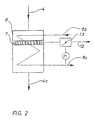
- the mixing insert 7 is direct integrated into the actual charge air cooler 8. It can also Mixing insert 7 for example for repair or maintenance from the Charge air cooler 8 can be removed. So this intercooler can 8 also for example in the case of a self-igniting version of the corresponding one Internal combustion engine series without further changes be used.
- FIG. 3 The embodiment of Figure 3 largely corresponds to that Overall view according to FIG. 1, the difference here being the Mixing insert 7 is designed as a venturi mixer 14.
- This venturi mixer 14 can optionally be used as a fixed gap mixer with an external Control element 13 - as shown - be designed or as a vario mixer with modifiable mixing gap.
Landscapes
- Engineering & Computer Science (AREA)
- Chemical & Material Sciences (AREA)
- General Engineering & Computer Science (AREA)
- Combustion & Propulsion (AREA)
- Mechanical Engineering (AREA)
- Thermal Sciences (AREA)
- Physics & Mathematics (AREA)
- Chemical Kinetics & Catalysis (AREA)
- General Chemical & Material Sciences (AREA)
- Oil, Petroleum & Natural Gas (AREA)
- Supercharger (AREA)
- Exhaust Gas After Treatment (AREA)
- Cylinder Crankcases Of Internal Combustion Engines (AREA)
- Exhaust-Gas Circulating Devices (AREA)
Abstract
Description
- Fig. 1:
- eine schematische Gesamtansicht mit einem in Strömungsrichtung vor dem Ladeluftkühler angeordneten Mischeinsatz und
- Fig. 2:
- eine Detailansicht eines Ladeluftkühlers mit integriertem Mischeinsatz.
- Fig. 3:
- eine schematische Gesamtansicht mit einem in Strömungsrichtung vor dem Ladeluftkühler angeordneten nach dem Venturi-Prinzip arbeitenden Mischeinsatz.
Claims (10)
- Brennkraftmaschine mit einem Kurbelgehäuse, in dem eine Kurbelwelle drehbar gelagert ist, an der zumindest ein einen Kolben tragendes Pleuel angelenkt ist, wobei der Kolben in einem von einem Zylinderkopf abgedeckten Zylinder unter Bildung eines Arbeitsraums bewegbar ist, dem ein Gas-Luft-Gemisch zuführbar ist, wobei das Gas und die Verbrennungsluft vor dem Arbeitsraum der Brennkraftmaschine zusammengeführt werden,
dadurch gekennzeichnet, dass das Gas der Verbrennungsluft über einen großflächigen Mischeinsatz (7), der in eine Verbrennungsluftleitung (4) einsetzbar ist, zugemischt wird. - Brennkraftmaschine nach Anspruch 1,
dadurch gekennzeichnet, dass der Mischeinsatz (7) bei einer mit Abgasturboaufladung und Ladeluftkühlung versehenen Brennkraftmaschine (1) in Strömungsrichtung hinter dem Abgasturbolader (3) und vor dem Ladeluftkühler (8) angeordnet ist. - Brennkraftmaschine nach Anspruch 1,
dadurch gekennzeichnet, dass der Mischeinsatz (7) bei einer mit Abgasturboaufladung und Ladeluftkühlung versehenen Brennkraftmaschine (1) in den Ladeluftkühler (8) integriert ist. - Brennkraftmaschine nach Anspruch 3,
dadurch gekennzeichnet, dass der Mischeinsatz (7) Bestandteil des Ladeluftkühlers (5) ist. - Brennkraftmaschine nach Anspruch 1,
dadurch gekennzeichnet, dass der Mischeinsatz (7) bei einer mit Abgasturboladung und Ladeluftkühlung versehenen Brennkraftmaschine (1) hinter den Ladeluftkühler (5) angeordnet ist. - Brennkraftmaschine nach einem der vorherigen Ansprüche,
dadurch gekennzeichnet, dass der Mischeinsatz (7) ein Venturi-Mischer (14) ist. - Brennkraftmaschine nach einem der vorherigen Ansprüche,
dadurch gekennzeichnet, dass der Mischeinsatz (7) rohrförmig ausgebildet ist, wobei die Verbrennungsluft zwischen den Rohren hindurchführbar ist und das Gas durch Öffnungen in den Rohren austritt. - Brennkraftmaschine nach einem der vorherigen Ansprüche,
dadurch gekennzeichnet, dass der Mischeinsatz (7) gitterförmig ausgebildet ist, wobei die Verbrennungsluft zwischen den Gitterrohren hindurchführbar ist und das Gas durch Öffnungen in den Gitterrohren austritt. - Brennkraftmaschine nach einem der vorherigen Ansprüche,
dadurch gekennzeichnet, dass der Mischeinsatz (7) netzförmig ausgebildet ist, wobei die Verbrennungsluft durch die Netzmaschen hindurchführbar ist und das Gas durch Öffnungen in dem Netzgewebe austritt. - Brennkraftmaschine nach einem der vorherigen Ansprüche,
dadurch gekennzeichnet, dass der Gasdruck vor dem Mischeinsatz (7) in Abhängigkeit von dem Druck im Bereich des Ladeluftkühlers (5) und/oder in Abhängigkeit der erforderlichen Betriebsparameter durch ein Stellglied (13) geregelt wird.
Applications Claiming Priority (2)
| Application Number | Priority Date | Filing Date | Title |
|---|---|---|---|
| DE10008959 | 2000-02-25 | ||
| DE10008959A DE10008959A1 (de) | 2000-02-25 | 2000-02-25 | Gasmischvorrichtung für stationäre und instationäre Otto-Gasmotoren |
Publications (3)
| Publication Number | Publication Date |
|---|---|
| EP1128053A2 true EP1128053A2 (de) | 2001-08-29 |
| EP1128053A3 EP1128053A3 (de) | 2002-04-03 |
| EP1128053B1 EP1128053B1 (de) | 2005-07-27 |
Family
ID=7632439
Family Applications (1)
| Application Number | Title | Priority Date | Filing Date |
|---|---|---|---|
| EP01104238A Expired - Lifetime EP1128053B1 (de) | 2000-02-25 | 2001-02-22 | Gasmischvorrichtung für stationäre und instationäre Otto-Gasmotoren |
Country Status (3)
| Country | Link |
|---|---|
| EP (1) | EP1128053B1 (de) |
| AT (1) | ATE300672T1 (de) |
| DE (2) | DE10008959A1 (de) |
Cited By (3)
| Publication number | Priority date | Publication date | Assignee | Title |
|---|---|---|---|---|
| US7240669B2 (en) * | 2003-08-29 | 2007-07-10 | Daimlerchrysler Ag | Method of operating an internal combustion engine with a dual fuel injection system |
| EP2336526A1 (de) * | 2003-07-07 | 2011-06-22 | Behr GmbH & Co. KG | Vorrichtung zur Zuführung eines Gemisches zu Saugstutzen von Zylinern eines Verbrennungsmotors |
| US20230070025A1 (en) * | 2021-09-01 | 2023-03-09 | American CNG, LLC | Supplemental fuel system for compression-ignition engine |
Citations (1)
| Publication number | Priority date | Publication date | Assignee | Title |
|---|---|---|---|---|
| DE2722226A1 (de) | 1977-05-17 | 1978-11-23 | Herbert Kabisch | Vorrichtung zum zerstaeuben von fluessigkeiten und zum mischen von gasen |
Family Cites Families (11)
| Publication number | Priority date | Publication date | Assignee | Title |
|---|---|---|---|---|
| DE2708824A1 (de) * | 1977-03-01 | 1978-09-07 | Siemens Ag | Vorrichtung zum dosieren und mischen von brenngas und luft fuer den betrieb von brennkraftmaschinen |
| US4398521A (en) * | 1981-08-19 | 1983-08-16 | John M. McNamara | Dual flow propane unit |
| DE3327699A1 (de) * | 1983-08-01 | 1985-02-21 | Motoren-Werke Mannheim AG vorm. Benz Abt. stationärer Motorenbau, 6800 Mannheim | Einrichtung zur anpassung an gase unterschiedlicher heizwerte bei der gas-luft-gemisch-versorgung von gasmotoren |
| JPH0626405A (ja) * | 1992-07-08 | 1994-02-01 | Nippon Carbureter Co Ltd | 気体燃料混合器 |
| US5408978A (en) * | 1993-05-03 | 1995-04-25 | Davis Family Trust | Gaseous fuel entrainment apparatus and process |
| US5377646A (en) * | 1993-09-10 | 1995-01-03 | Pacer Industries, Inc. | Liquid petroleum gas fuel delivery systems |
| US5595163A (en) * | 1995-06-06 | 1997-01-21 | Hitachi America, Ltd. | Apparatus and method for controlling the fuel supply of a gas-fueled engine |
| DE19634299A1 (de) * | 1996-08-24 | 1998-02-26 | Motoren Werke Mannheim Ag | Gasmotor mit Walzen-Drehschieber |
| US5913239A (en) * | 1997-06-17 | 1999-06-15 | Cummins Engine Company, Inc. | Mass flow measurement device |
| JPH11159403A (ja) * | 1997-11-28 | 1999-06-15 | Mitsubishi Heavy Ind Ltd | 液化ガス燃料エンジンの吸入装置 |
| JPH11324812A (ja) * | 1998-05-20 | 1999-11-26 | Hino Motors Ltd | ベンチュリ型ミキサ |
-
2000
- 2000-02-25 DE DE10008959A patent/DE10008959A1/de not_active Withdrawn
-
2001
- 2001-02-22 AT AT01104238T patent/ATE300672T1/de active
- 2001-02-22 EP EP01104238A patent/EP1128053B1/de not_active Expired - Lifetime
- 2001-02-22 DE DE50106838T patent/DE50106838D1/de not_active Expired - Lifetime
Patent Citations (1)
| Publication number | Priority date | Publication date | Assignee | Title |
|---|---|---|---|---|
| DE2722226A1 (de) | 1977-05-17 | 1978-11-23 | Herbert Kabisch | Vorrichtung zum zerstaeuben von fluessigkeiten und zum mischen von gasen |
Cited By (12)
| Publication number | Priority date | Publication date | Assignee | Title |
|---|---|---|---|---|
| EP2336526A1 (de) * | 2003-07-07 | 2011-06-22 | Behr GmbH & Co. KG | Vorrichtung zur Zuführung eines Gemisches zu Saugstutzen von Zylinern eines Verbrennungsmotors |
| US7240669B2 (en) * | 2003-08-29 | 2007-07-10 | Daimlerchrysler Ag | Method of operating an internal combustion engine with a dual fuel injection system |
| US20230070025A1 (en) * | 2021-09-01 | 2023-03-09 | American CNG, LLC | Supplemental fuel system for compression-ignition engine |
| US11739716B2 (en) | 2021-09-01 | 2023-08-29 | American CNG, LLC | Supplemental fuel system for compression-ignition engine |
| US11767811B2 (en) * | 2021-09-01 | 2023-09-26 | American CNG, LLC | Supplemental fuel system for compression-ignition engine |
| US11808221B2 (en) | 2021-09-01 | 2023-11-07 | American CNG, LLC | Supplemental fuel system for compression-ignition engine |
| US11835016B2 (en) | 2021-09-01 | 2023-12-05 | American CNG, LLC | Supplemental fuel system for compression-ignition engine |
| US11988175B2 (en) | 2021-09-01 | 2024-05-21 | American CNG, LLC | Supplemental fuel system for compression-ignition engine |
| US11994091B2 (en) | 2021-09-01 | 2024-05-28 | American CNG, LLC | Supplemental fuel system for compression-ignition engine |
| US12025081B2 (en) | 2021-09-01 | 2024-07-02 | American CNG, LLC | Supplemental fuel system for compression-ignition engine |
| US12116959B2 (en) | 2021-09-01 | 2024-10-15 | American CNG, LLC | Supplemental fuel system for compression-ignition engine |
| US12510043B2 (en) | 2021-09-01 | 2025-12-30 | American CNG, LLC | Supplemental fuel system for compression-ignition engine |
Also Published As
| Publication number | Publication date |
|---|---|
| ATE300672T1 (de) | 2005-08-15 |
| DE50106838D1 (de) | 2005-09-01 |
| EP1128053A3 (de) | 2002-04-03 |
| DE10008959A1 (de) | 2001-08-30 |
| EP1128053B1 (de) | 2005-07-27 |
Similar Documents
| Publication | Publication Date | Title |
|---|---|---|
| DE69703334T2 (de) | Wärmerückgewinnungsvorrichtung für Wärme-Kraftsysteme mit einer Brennkraftmaschine | |
| DE10354839A1 (de) | Kompressionsgezündete Motortechnologie mit niedrigen Emissionen | |
| WO2023036710A1 (de) | Verfahren zum betreiben einer brennkraftmaschine und brennkraftmaschine | |
| DE2644389B2 (de) | ||
| DE60221249T2 (de) | Verfahren zur kraftstoffeinspritzung in einen verbrennungsmotor und verbrennungsmotor | |
| AT518811B1 (de) | Gasmotor und Verfahren zum Betreiben desselben | |
| DE102008045915A1 (de) | Brennkraftmaschine mit Vorkammerzündung | |
| EP3786424A1 (de) | Fremdgezündete brennkraftmaschine mit innerer gemischbildung zur verbrennung eines gemischs aus einem gasförmigen kraftstoff und luft | |
| EP1128053B1 (de) | Gasmischvorrichtung für stationäre und instationäre Otto-Gasmotoren | |
| DE102019105033B4 (de) | System zur abgasrückführung | |
| EP1417405B1 (de) | Verfahren zur regelung eines verbrennungsmotors mit abgasrückführung sowie einrichtung zur durchführung des verfahrens | |
| DE2235004A1 (de) | Verfahren zur verbesserung von leistung und verbrauch bei freisaugenden, gemischverdichtenden, fremdgezuendeten brennkraftmaschinen mit besonders intensiver abgasentgiftung durch verwendung von in einem ausserhalb der brennkraftmaschine angeordneten vergasungsreaktor mittels partieller verbrennung fluessiger brennstoffe erzeugtem brenngas | |
| DE102017116799A1 (de) | Wärmekraftmaschine, Verfahren zum Betrieb einer solchen Wärmekraftmaschine, Kraftfahrzeug und Blockheizkraftwerk | |
| DE2613589A1 (de) | Verbrennungseinrichtung fuer eine gasturbine | |
| EP4419783B1 (de) | Brennkraftmaschine sowie verfahren zum betreiben einer brennkraftmaschine | |
| WO2003044349A1 (de) | Verbrennungsmotor | |
| AT524226B1 (de) | Verbrennungsmotor und Verfahren zum Betreiben eines Verbrennungsmotors | |
| EP1557607B1 (de) | Brenner mit gekühltem Bauteil, Gasturbine sowie Verfahren zur Kühlung des Bauteils | |
| DE10237596B4 (de) | Optimierung des Beschleunigungsverhaltens von gemischaufgeladenen Otto-/Diesel-/ oder Zündstrahl-Gasmotoren | |
| DE102010012411B4 (de) | Brennkraftmaschine mit Verdichtungseinrichtung | |
| DE102005062255B4 (de) | Verbrennungskraftmaschine mit innerer Verbrennung | |
| DE829679C (de) | Foerdervorrichtung, insbesondere fuer den Brennstoff von Kolbenbrennkraftmaschinen | |
| WO2016169712A1 (de) | Einlasskanaleinrichtung einer maschine | |
| DE2434862C3 (de) | Vorrichtung zur Herstellung eines Kraftstoff-Luft-Gemisches bei mit Schichtladebetrieb wirkenden Brennkraftmaschinen | |
| DE2936043A1 (de) | Zweitakt-brennkraftmaschine. |
Legal Events
| Date | Code | Title | Description |
|---|---|---|---|
| PUAI | Public reference made under article 153(3) epc to a published international application that has entered the european phase |
Free format text: ORIGINAL CODE: 0009012 |
|
| AK | Designated contracting states |
Kind code of ref document: A2 Designated state(s): AT DE FR GB Kind code of ref document: A2 Designated state(s): AT BE CH CY DE DK ES FI FR GB GR IE IT LI LU MC NL PT SE TR |
|
| AX | Request for extension of the european patent |
Free format text: AL;LT;LV;MK;RO;SI |
|
| PUAL | Search report despatched |
Free format text: ORIGINAL CODE: 0009013 |
|
| AK | Designated contracting states |
Kind code of ref document: A3 Designated state(s): AT BE CH CY DE DK ES FI FR GB GR IE IT LI LU MC NL PT SE TR |
|
| AX | Request for extension of the european patent |
Free format text: AL;LT;LV;MK;RO;SI |
|
| RIC1 | Information provided on ipc code assigned before grant |
Free format text: 7F 02M 21/04 A, 7F 02B 29/04 B, 7F 02D 19/02 B |
|
| 17P | Request for examination filed |
Effective date: 20020516 |
|
| AKX | Designation fees paid |
Free format text: AT DE FR GB |
|
| 17Q | First examination report despatched |
Effective date: 20040301 |
|
| GRAP | Despatch of communication of intention to grant a patent |
Free format text: ORIGINAL CODE: EPIDOSNIGR1 |
|
| GRAS | Grant fee paid |
Free format text: ORIGINAL CODE: EPIDOSNIGR3 |
|
| GRAA | (expected) grant |
Free format text: ORIGINAL CODE: 0009210 |
|
| AK | Designated contracting states |
Kind code of ref document: B1 Designated state(s): AT DE FR GB |
|
| PG25 | Lapsed in a contracting state [announced via postgrant information from national office to epo] |
Ref country code: GB Free format text: LAPSE BECAUSE OF FAILURE TO SUBMIT A TRANSLATION OF THE DESCRIPTION OR TO PAY THE FEE WITHIN THE PRESCRIBED TIME-LIMIT Effective date: 20050727 |
|
| REG | Reference to a national code |
Ref country code: GB Ref legal event code: FG4D Free format text: NOT ENGLISH |
|
| REF | Corresponds to: |
Ref document number: 50106838 Country of ref document: DE Date of ref document: 20050901 Kind code of ref document: P |
|
| GBV | Gb: ep patent (uk) treated as always having been void in accordance with gb section 77(7)/1977 [no translation filed] |
Effective date: 20050727 |
|
| PLBE | No opposition filed within time limit |
Free format text: ORIGINAL CODE: 0009261 |
|
| STAA | Information on the status of an ep patent application or granted ep patent |
Free format text: STATUS: NO OPPOSITION FILED WITHIN TIME LIMIT |
|
| 26N | No opposition filed |
Effective date: 20060428 |
|
| EN | Fr: translation not filed | ||
| PG25 | Lapsed in a contracting state [announced via postgrant information from national office to epo] |
Ref country code: FR Free format text: LAPSE BECAUSE OF FAILURE TO SUBMIT A TRANSLATION OF THE DESCRIPTION OR TO PAY THE FEE WITHIN THE PRESCRIBED TIME-LIMIT Effective date: 20060922 |
|
| PG25 | Lapsed in a contracting state [announced via postgrant information from national office to epo] |
Ref country code: FR Free format text: LAPSE BECAUSE OF FAILURE TO SUBMIT A TRANSLATION OF THE DESCRIPTION OR TO PAY THE FEE WITHIN THE PRESCRIBED TIME-LIMIT Effective date: 20050727 |
|
| REG | Reference to a national code |
Ref country code: AT Ref legal event code: HC Ref document number: 300672 Country of ref document: AT Kind code of ref document: T Owner name: MWM GMBH, DE Effective date: 20120807 |
|
| REG | Reference to a national code |
Ref country code: DE Ref legal event code: R082 Ref document number: 50106838 Country of ref document: DE Representative=s name: KRAMER BARSKE SCHMIDTCHEN PATENTANWAELTE PARTG, DE Effective date: 20120830 Ref country code: DE Ref legal event code: R082 Ref document number: 50106838 Country of ref document: DE Representative=s name: KRAMER - BARSKE - SCHMIDTCHEN, DE Effective date: 20120830 Ref country code: DE Ref legal event code: R082 Ref document number: 50106838 Country of ref document: DE Representative=s name: STT SOZIETAET THEWS & THEWS, DE Effective date: 20120830 Ref country code: DE Ref legal event code: R081 Ref document number: 50106838 Country of ref document: DE Owner name: MWM GMBH, DE Free format text: FORMER OWNER: DEUTZ POWER SYSTEMS GMBH, 68167 MANNHEIM, DE Effective date: 20120830 Ref country code: DE Ref legal event code: R081 Ref document number: 50106838 Country of ref document: DE Owner name: CATERPILLAR ENERGY SOLUTIONS GMBH, DE Free format text: FORMER OWNER: DEUTZ POWER SYSTEMS GMBH, 68167 MANNHEIM, DE Effective date: 20120830 |
|
| REG | Reference to a national code |
Ref country code: DE Ref legal event code: R082 Ref document number: 50106838 Country of ref document: DE Representative=s name: KRAMER - BARSKE - SCHMIDTCHEN, DE |
|
| REG | Reference to a national code |
Ref country code: DE Ref legal event code: R082 Ref document number: 50106838 Country of ref document: DE Representative=s name: KRAMER - BARSKE - SCHMIDTCHEN, DE |
|
| REG | Reference to a national code |
Ref country code: DE Ref legal event code: R082 Ref document number: 50106838 Country of ref document: DE Representative=s name: KRAMER BARSKE SCHMIDTCHEN PATENTANWAELTE PARTG, DE Effective date: 20140207 Ref country code: DE Ref legal event code: R082 Ref document number: 50106838 Country of ref document: DE Representative=s name: KRAMER BARSKE SCHMIDTCHEN PATENTANWAELTE PARTG, DE Effective date: 20140902 Ref country code: DE Ref legal event code: R082 Ref document number: 50106838 Country of ref document: DE Representative=s name: KRAMER - BARSKE - SCHMIDTCHEN, DE Effective date: 20140902 Ref country code: DE Ref legal event code: R081 Ref document number: 50106838 Country of ref document: DE Owner name: CATERPILLAR ENERGY SOLUTIONS GMBH, DE Free format text: FORMER OWNER: MWM GMBH, 68167 MANNHEIM, DE Effective date: 20140902 Ref country code: DE Ref legal event code: R082 Ref document number: 50106838 Country of ref document: DE Representative=s name: KRAMER - BARSKE - SCHMIDTCHEN, DE Effective date: 20140207 |
|
| PGFP | Annual fee paid to national office [announced via postgrant information from national office to epo] |
Ref country code: AT Payment date: 20150126 Year of fee payment: 15 |
|
| PGFP | Annual fee paid to national office [announced via postgrant information from national office to epo] |
Ref country code: DE Payment date: 20160302 Year of fee payment: 16 |
|
| REG | Reference to a national code |
Ref country code: AT Ref legal event code: MM01 Ref document number: 300672 Country of ref document: AT Kind code of ref document: T Effective date: 20160222 |
|
| PG25 | Lapsed in a contracting state [announced via postgrant information from national office to epo] |
Ref country code: AT Free format text: LAPSE BECAUSE OF NON-PAYMENT OF DUE FEES Effective date: 20160222 |
|
| REG | Reference to a national code |
Ref country code: DE Ref legal event code: R119 Ref document number: 50106838 Country of ref document: DE |
|
| PG25 | Lapsed in a contracting state [announced via postgrant information from national office to epo] |
Ref country code: DE Free format text: LAPSE BECAUSE OF NON-PAYMENT OF DUE FEES Effective date: 20170901 |