EP1128031A1 - Méthode pour la fabrication d'une structure en nid d'abeilles comprenant des fentes et appareil pour la fabrication de celle-ci - Google Patents
Méthode pour la fabrication d'une structure en nid d'abeilles comprenant des fentes et appareil pour la fabrication de celle-ci Download PDFInfo
- Publication number
- EP1128031A1 EP1128031A1 EP01102276A EP01102276A EP1128031A1 EP 1128031 A1 EP1128031 A1 EP 1128031A1 EP 01102276 A EP01102276 A EP 01102276A EP 01102276 A EP01102276 A EP 01102276A EP 1128031 A1 EP1128031 A1 EP 1128031A1
- Authority
- EP
- European Patent Office
- Prior art keywords
- slits
- honeycomb structure
- forming member
- manufacturing
- slit forming
- Prior art date
- Legal status (The legal status is an assumption and is not a legal conclusion. Google has not performed a legal analysis and makes no representation as to the accuracy of the status listed.)
- Granted
Links
- 238000004519 manufacturing process Methods 0.000 title claims abstract description 72
- 238000000034 method Methods 0.000 title claims abstract description 53
- 238000003491 array Methods 0.000 claims abstract description 53
- 238000001125 extrusion Methods 0.000 claims description 30
- 238000005520 cutting process Methods 0.000 claims description 23
- 238000012544 monitoring process Methods 0.000 claims description 20
- 230000015572 biosynthetic process Effects 0.000 claims description 16
- 230000001276 controlling effect Effects 0.000 claims 1
- 210000004027 cell Anatomy 0.000 description 103
- 238000003754 machining Methods 0.000 description 23
- 238000010304 firing Methods 0.000 description 15
- 210000002421 cell wall Anatomy 0.000 description 13
- 238000001035 drying Methods 0.000 description 13
- 239000007788 liquid Substances 0.000 description 13
- 230000000052 comparative effect Effects 0.000 description 12
- 239000000203 mixture Substances 0.000 description 11
- 238000007789 sealing Methods 0.000 description 10
- 238000000926 separation method Methods 0.000 description 10
- 239000000706 filtrate Substances 0.000 description 8
- 239000011148 porous material Substances 0.000 description 8
- 238000000227 grinding Methods 0.000 description 7
- 239000000919 ceramic Substances 0.000 description 5
- 238000007796 conventional method Methods 0.000 description 5
- 239000004575 stone Substances 0.000 description 5
- 230000006835 compression Effects 0.000 description 4
- 238000007906 compression Methods 0.000 description 4
- 238000001914 filtration Methods 0.000 description 4
- 239000012778 molding material Substances 0.000 description 4
- GWEVSGVZZGPLCZ-UHFFFAOYSA-N Titan oxide Chemical compound O=[Ti]=O GWEVSGVZZGPLCZ-UHFFFAOYSA-N 0.000 description 2
- MCMNRKCIXSYSNV-UHFFFAOYSA-N Zirconium dioxide Chemical compound O=[Zr]=O MCMNRKCIXSYSNV-UHFFFAOYSA-N 0.000 description 2
- PNEYBMLMFCGWSK-UHFFFAOYSA-N aluminium oxide Inorganic materials [O-2].[O-2].[O-2].[Al+3].[Al+3] PNEYBMLMFCGWSK-UHFFFAOYSA-N 0.000 description 2
- 239000011230 binding agent Substances 0.000 description 2
- 230000008602 contraction Effects 0.000 description 2
- 229910003460 diamond Inorganic materials 0.000 description 2
- 239000010432 diamond Substances 0.000 description 2
- 210000000887 face Anatomy 0.000 description 2
- 239000000463 material Substances 0.000 description 2
- 230000002093 peripheral effect Effects 0.000 description 2
- 239000000843 powder Substances 0.000 description 2
- 229910000997 High-speed steel Inorganic materials 0.000 description 1
- 238000005452 bending Methods 0.000 description 1
- 239000003054 catalyst Substances 0.000 description 1
- 229910010293 ceramic material Inorganic materials 0.000 description 1
- 230000000295 complement effect Effects 0.000 description 1
- 238000011109 contamination Methods 0.000 description 1
- 229910052878 cordierite Inorganic materials 0.000 description 1
- 238000001514 detection method Methods 0.000 description 1
- 238000010586 diagram Methods 0.000 description 1
- JSKIRARMQDRGJZ-UHFFFAOYSA-N dimagnesium dioxido-bis[(1-oxido-3-oxo-2,4,6,8,9-pentaoxa-1,3-disila-5,7-dialuminabicyclo[3.3.1]nonan-7-yl)oxy]silane Chemical compound [Mg++].[Mg++].[O-][Si]([O-])(O[Al]1O[Al]2O[Si](=O)O[Si]([O-])(O1)O2)O[Al]1O[Al]2O[Si](=O)O[Si]([O-])(O1)O2 JSKIRARMQDRGJZ-UHFFFAOYSA-N 0.000 description 1
- KZHJGOXRZJKJNY-UHFFFAOYSA-N dioxosilane;oxo(oxoalumanyloxy)alumane Chemical compound O=[Si]=O.O=[Si]=O.O=[Al]O[Al]=O.O=[Al]O[Al]=O.O=[Al]O[Al]=O KZHJGOXRZJKJNY-UHFFFAOYSA-N 0.000 description 1
- 238000007598 dipping method Methods 0.000 description 1
- 239000000428 dust Substances 0.000 description 1
- 230000008030 elimination Effects 0.000 description 1
- 238000003379 elimination reaction Methods 0.000 description 1
- 239000012530 fluid Substances 0.000 description 1
- 239000011521 glass Substances 0.000 description 1
- 238000000465 moulding Methods 0.000 description 1
- 229910052863 mullite Inorganic materials 0.000 description 1
- 239000002245 particle Substances 0.000 description 1
- 239000004014 plasticizer Substances 0.000 description 1
- 238000000746 purification Methods 0.000 description 1
- 230000000717 retained effect Effects 0.000 description 1
- 239000002904 solvent Substances 0.000 description 1
- 239000004094 surface-active agent Substances 0.000 description 1
- XLYOFNOQVPJJNP-UHFFFAOYSA-N water Substances O XLYOFNOQVPJJNP-UHFFFAOYSA-N 0.000 description 1
Images


Classifications
-
- B—PERFORMING OPERATIONS; TRANSPORTING
- B28—WORKING CEMENT, CLAY, OR STONE
- B28B—SHAPING CLAY OR OTHER CERAMIC COMPOSITIONS; SHAPING SLAG; SHAPING MIXTURES CONTAINING CEMENTITIOUS MATERIAL, e.g. PLASTER
- B28B11/00—Apparatus or processes for treating or working the shaped or preshaped articles
- B28B11/12—Apparatus or processes for treating or working the shaped or preshaped articles for removing parts of the articles by cutting
- B28B11/125—Cutting-off protruding ridges, also profiled cutting
-
- B—PERFORMING OPERATIONS; TRANSPORTING
- B01—PHYSICAL OR CHEMICAL PROCESSES OR APPARATUS IN GENERAL
- B01J—CHEMICAL OR PHYSICAL PROCESSES, e.g. CATALYSIS OR COLLOID CHEMISTRY; THEIR RELEVANT APPARATUS
- B01J35/00—Catalysts, in general, characterised by their form or physical properties
- B01J35/50—Catalysts, in general, characterised by their form or physical properties characterised by their shape or configuration
- B01J35/56—Foraminous structures having flow-through passages or channels, e.g. grids or three-dimensional monoliths
-
- B—PERFORMING OPERATIONS; TRANSPORTING
- B29—WORKING OF PLASTICS; WORKING OF SUBSTANCES IN A PLASTIC STATE IN GENERAL
- B29C—SHAPING OR JOINING OF PLASTICS; SHAPING OF MATERIAL IN A PLASTIC STATE, NOT OTHERWISE PROVIDED FOR; AFTER-TREATMENT OF THE SHAPED PRODUCTS, e.g. REPAIRING
- B29C48/00—Extrusion moulding, i.e. expressing the moulding material through a die or nozzle which imparts the desired form; Apparatus therefor
- B29C48/03—Extrusion moulding, i.e. expressing the moulding material through a die or nozzle which imparts the desired form; Apparatus therefor characterised by the shape of the extruded material at extrusion
- B29C48/09—Articles with cross-sections having partially or fully enclosed cavities, e.g. pipes or channels
- B29C48/11—Articles with cross-sections having partially or fully enclosed cavities, e.g. pipes or channels comprising two or more partially or fully enclosed cavities, e.g. honeycomb-shaped
-
- B—PERFORMING OPERATIONS; TRANSPORTING
- B29—WORKING OF PLASTICS; WORKING OF SUBSTANCES IN A PLASTIC STATE IN GENERAL
- B29C—SHAPING OR JOINING OF PLASTICS; SHAPING OF MATERIAL IN A PLASTIC STATE, NOT OTHERWISE PROVIDED FOR; AFTER-TREATMENT OF THE SHAPED PRODUCTS, e.g. REPAIRING
- B29C48/00—Extrusion moulding, i.e. expressing the moulding material through a die or nozzle which imparts the desired form; Apparatus therefor
- B29C48/25—Component parts, details or accessories; Auxiliary operations
- B29C48/92—Measuring, controlling or regulating
-
- F—MECHANICAL ENGINEERING; LIGHTING; HEATING; WEAPONS; BLASTING
- F01—MACHINES OR ENGINES IN GENERAL; ENGINE PLANTS IN GENERAL; STEAM ENGINES
- F01N—GAS-FLOW SILENCERS OR EXHAUST APPARATUS FOR MACHINES OR ENGINES IN GENERAL; GAS-FLOW SILENCERS OR EXHAUST APPARATUS FOR INTERNAL COMBUSTION ENGINES
- F01N3/00—Exhaust or silencing apparatus having means for purifying, rendering innocuous, or otherwise treating exhaust
- F01N3/02—Exhaust or silencing apparatus having means for purifying, rendering innocuous, or otherwise treating exhaust for cooling, or for removing solid constituents of, exhaust
- F01N3/021—Exhaust or silencing apparatus having means for purifying, rendering innocuous, or otherwise treating exhaust for cooling, or for removing solid constituents of, exhaust by means of filters
- F01N3/022—Exhaust or silencing apparatus having means for purifying, rendering innocuous, or otherwise treating exhaust for cooling, or for removing solid constituents of, exhaust by means of filters characterised by specially adapted filtering structure, e.g. honeycomb, mesh or fibrous
- F01N3/0222—Exhaust or silencing apparatus having means for purifying, rendering innocuous, or otherwise treating exhaust for cooling, or for removing solid constituents of, exhaust by means of filters characterised by specially adapted filtering structure, e.g. honeycomb, mesh or fibrous the structure being monolithic, e.g. honeycombs
-
- F—MECHANICAL ENGINEERING; LIGHTING; HEATING; WEAPONS; BLASTING
- F01—MACHINES OR ENGINES IN GENERAL; ENGINE PLANTS IN GENERAL; STEAM ENGINES
- F01N—GAS-FLOW SILENCERS OR EXHAUST APPARATUS FOR MACHINES OR ENGINES IN GENERAL; GAS-FLOW SILENCERS OR EXHAUST APPARATUS FOR INTERNAL COMBUSTION ENGINES
- F01N3/00—Exhaust or silencing apparatus having means for purifying, rendering innocuous, or otherwise treating exhaust
- F01N3/08—Exhaust or silencing apparatus having means for purifying, rendering innocuous, or otherwise treating exhaust for rendering innocuous
- F01N3/10—Exhaust or silencing apparatus having means for purifying, rendering innocuous, or otherwise treating exhaust for rendering innocuous by thermal or catalytic conversion of noxious components of exhaust
- F01N3/24—Exhaust or silencing apparatus having means for purifying, rendering innocuous, or otherwise treating exhaust for rendering innocuous by thermal or catalytic conversion of noxious components of exhaust characterised by constructional aspects of converting apparatus
- F01N3/28—Construction of catalytic reactors
- F01N3/2803—Construction of catalytic reactors characterised by structure, by material or by manufacturing of catalyst support
- F01N3/2825—Ceramics
- F01N3/2828—Ceramic multi-channel monoliths, e.g. honeycombs
-
- B—PERFORMING OPERATIONS; TRANSPORTING
- B29—WORKING OF PLASTICS; WORKING OF SUBSTANCES IN A PLASTIC STATE IN GENERAL
- B29C—SHAPING OR JOINING OF PLASTICS; SHAPING OF MATERIAL IN A PLASTIC STATE, NOT OTHERWISE PROVIDED FOR; AFTER-TREATMENT OF THE SHAPED PRODUCTS, e.g. REPAIRING
- B29C2948/00—Indexing scheme relating to extrusion moulding
- B29C2948/92—Measuring, controlling or regulating
- B29C2948/92009—Measured parameter
- B29C2948/92076—Position, e.g. linear or angular
-
- B—PERFORMING OPERATIONS; TRANSPORTING
- B29—WORKING OF PLASTICS; WORKING OF SUBSTANCES IN A PLASTIC STATE IN GENERAL
- B29C—SHAPING OR JOINING OF PLASTICS; SHAPING OF MATERIAL IN A PLASTIC STATE, NOT OTHERWISE PROVIDED FOR; AFTER-TREATMENT OF THE SHAPED PRODUCTS, e.g. REPAIRING
- B29C2948/00—Indexing scheme relating to extrusion moulding
- B29C2948/92—Measuring, controlling or regulating
- B29C2948/92323—Location or phase of measurement
- B29C2948/92447—Moulded article
-
- B—PERFORMING OPERATIONS; TRANSPORTING
- B29—WORKING OF PLASTICS; WORKING OF SUBSTANCES IN A PLASTIC STATE IN GENERAL
- B29C—SHAPING OR JOINING OF PLASTICS; SHAPING OF MATERIAL IN A PLASTIC STATE, NOT OTHERWISE PROVIDED FOR; AFTER-TREATMENT OF THE SHAPED PRODUCTS, e.g. REPAIRING
- B29C2948/00—Indexing scheme relating to extrusion moulding
- B29C2948/92—Measuring, controlling or regulating
- B29C2948/92504—Controlled parameter
- B29C2948/92571—Position, e.g. linear or angular
-
- B—PERFORMING OPERATIONS; TRANSPORTING
- B29—WORKING OF PLASTICS; WORKING OF SUBSTANCES IN A PLASTIC STATE IN GENERAL
- B29C—SHAPING OR JOINING OF PLASTICS; SHAPING OF MATERIAL IN A PLASTIC STATE, NOT OTHERWISE PROVIDED FOR; AFTER-TREATMENT OF THE SHAPED PRODUCTS, e.g. REPAIRING
- B29C2948/00—Indexing scheme relating to extrusion moulding
- B29C2948/92—Measuring, controlling or regulating
- B29C2948/92819—Location or phase of control
- B29C2948/92942—Moulded article
-
- F—MECHANICAL ENGINEERING; LIGHTING; HEATING; WEAPONS; BLASTING
- F01—MACHINES OR ENGINES IN GENERAL; ENGINE PLANTS IN GENERAL; STEAM ENGINES
- F01N—GAS-FLOW SILENCERS OR EXHAUST APPARATUS FOR MACHINES OR ENGINES IN GENERAL; GAS-FLOW SILENCERS OR EXHAUST APPARATUS FOR INTERNAL COMBUSTION ENGINES
- F01N2330/00—Structure of catalyst support or particle filter
- F01N2330/06—Ceramic, e.g. monoliths
-
- Y—GENERAL TAGGING OF NEW TECHNOLOGICAL DEVELOPMENTS; GENERAL TAGGING OF CROSS-SECTIONAL TECHNOLOGIES SPANNING OVER SEVERAL SECTIONS OF THE IPC; TECHNICAL SUBJECTS COVERED BY FORMER USPC CROSS-REFERENCE ART COLLECTIONS [XRACs] AND DIGESTS
- Y02—TECHNOLOGIES OR APPLICATIONS FOR MITIGATION OR ADAPTATION AGAINST CLIMATE CHANGE
- Y02T—CLIMATE CHANGE MITIGATION TECHNOLOGIES RELATED TO TRANSPORTATION
- Y02T10/00—Road transport of goods or passengers
- Y02T10/10—Internal combustion engine [ICE] based vehicles
- Y02T10/12—Improving ICE efficiencies
Definitions
- the present invention is directed to a method for manufacturing a honeycomb structure having slits and having a plurality of arrays of numerous cells aligned in parallel, an apparatus for manufacturing the same, and more particularly to a method for manufacturing a honeycomb structure having slits formed along arrays of numerous cells aligned in parallel and communicating with external space, and an apparatus for manufacturing the same.
- a honeycomb structure is known as a structure in which a plurality of arrays of numerous cells is formed by being aligned them in parallel to a base, and is used as a light yet strong structural member for aircraft or the like, and a catalyst carrier having a large air flow for automotive exhaust gas purification or the like. Additionally, it is utilized as a dust filter or a solid-liquid separation filter having a large filtering area per unit volume, in a case where the base is made of a ceramic porous material having fine pores.
- the aforementioned applications is derived from the feature of the honeycomb structure that it has a plurality of cells isolated from external space, however, slits communicating with external space are formed on the structure by deliberately cutting or grinding parts of the cells for certain purposes.
- a honeycomb structure 21 shown in Fig. 2 is a solid-liquid separation filter for removing insoluble matters of a particle diameter larger than the pores of a base 22 by injecting a liquid to be treated into cells 23 and by letting only a filtrate that has passed the pores of the base 22 flow out to external space.
- a part of the cells 23 is deliberately cut or ground along the specific cell arrays 26a out of a plurality of cell arrays 26 to form slits 24, thereby the structure can communicate with external space.
- Such a type of a honeycomb structure will be referred to hereinafter as a honeycomb structure having slits).
- the contamination of the filtrate with a liquid to be treated can be prevented merely by sealing the cell arrays 26a in which the slits 24 are formed at the both ends of said arrays 26a with a sealing member 25 made of glass or the like.
- a honeycomb structure having slits such as the one described above is manufactured by, after extruding, drying and firing ceramic body for instance,
- the elimination of the machining errors such as breaking arrays of adjacent cells or cutting cell walls of adjacent cells would not be possible even cutting the marked off portions accurately. This is because it is not so easy even for the well-experienced workers to cut or grind the targeted cell arrays alone, in addition to the troublesome manual work of marking off. This comes the fact that the cell arrays in which slits are to be formed are not always positioned along the lines connecting the cell arrays marked off at the end faces where cell openings are located of the structure due to the frequent distortion and/or frequent deformation of cell arrays marked off which is derived from the compression or the deformation of a molded article during the steps of extruding, drying and firing the molded article.
- the first method is not a simple one fitted for mass production, and furthermore it is difficult to form fine slits accurately.
- the difficulty in forming fine slits accurately means that the formation of slits in a honeycomb body of such a fine structure that the one having fine cell pores of 2 to 3 mm and having a wall thickness of about 0.5 mm is extremely difficult.
- the second method can reduce machining errors because slits are formed with watching the cell arrays with naked eyes, compared with the first method.
- it requires such a troublesome manual work that one should cut into the end faces of the structure with watching the cell arrays with naked eyes. Accordingly, one may say that fine slits can be formed accurately by utilizing the second method, however, there is a problem in that it is not simple to apply it to mass production.
- the mechanical strength at the two ends of the structure is weakened because inevitably slits are formed there.
- the weakened mechanical strength at the two ends of the structure is not preferable. This is because the filter is easily broken by the mechanical forces such as distortion or impact given thereto at the time of fitting it; and the bending stress derived from the dimensional tolerance of the structure or the surface pressure of sealing, in the case that one uses the structure as a solid-liquid separation filter by utilizing the both ends of the structure as a sealing portion at the time of fixing it at both ends.
- the formation of the slits is not so easy task in both the first method and the second method since a honeycomb structure hardened and densified after firing should be used for the processing of the slits in the both methods.
- the second method may be applied to a molded article before drying and firing, however, it is not preferable either since there is a fear of magnifying the contraction or deformation of the structure at the two ends at the time of drying and firing; this might cause sealing failure when the structure is used as a solid-liquid separation filter.
- any conventional method for manufacturing a honeycomb structure having slits is not satisfactory since it is furnished with neither formation of slits in accuracy and fineness nor sufficient simplicity fitted for mass production.
- the present invention has been made so as to solve those problems. That is, the object of the present invention is to provide a method for manufacturing a honeycomb structure having slits capable of forming accurately fine slits by cutting or grinding the specified cell arrays alone, and being fitted to mass production.
- the present invention has been completed, as a result of intensive studies, based on the findings that those problems mentioned above can be solved by adopting a slit forming method in which a slit forming member is protruded during the step of extruding a honeycomb structure.
- a method for manufacturing a honeycomb structure having slits and having a plurality of arrays of numerous cells alinged in parallel; the slits communicating with external space and being formed along the cell arrays, wherein the slits are formed during the step of extruding a honeycomb structure by protruding a slit forming member toward an molded article during that time.
- slits can be formed during the extrusion step with the formation of cells, or alternatively the slits may be formed by cutting the specified arrays after the formation of the cells.
- an apparatus for manufacturing a honeycomb structure having slits and a plurality of arrays of numerous cells aligned in parallel; the slits communicating with external space and being formed along the cell arrays which comprises an extruder having an extruding die for a honeycomb structure, and a slit forming member installed near the extruding die and capable of protruding along specified cell arrays of a molded article being extruded in which slits are to be formed.
- the slit forming member may be arranged so as to protrude toward either inwardly or outwardly the extruding die.
- a J-shaped bit is preferable as a slit forming member.
- monitoring means for monitoring the position of the molded article being extruded and control means for controlling the actions of the slit forming member based on the monitoring data.
- Fig. 1 shows a schematic cross section of a slit part in one preferred embodiment of a method for manufacturing a honeycomb structure having slits according to the present invention, wherein Fig. 1(A) shows how slits are formed only on an external wall portion of a molded article, and Fig. 1(B) shows how slits are formed in the internal of the molded article.
- Fig. 2 schematically illustrates a honeycomb structure having slits in one mode of implementing the present invention, wherein Fig. 2A shows an expanded view of a cell part and Fig. 2(B), a perspective view of the overall shape.
- Fig. 3 schematically illustrates a honeycomb structure having slits as another embodiment of the present honeycomb structure having slits, wherein Fig. 3(A) is a perspective view of the overall shape and Fig. 3(B), an expanded view of cell portion.
- Fig. 4 schematically illustrates a shape of an extrusion die.
- Figs. 5(A) through 5(C) schematically illustrate edge shapes of a slit forming member usable for the present apparatus.
- Figs. 6(A) through 6(G) schematically illustrate edge shapes of another slit forming member usable for the present apparatus.
- Fig. 7 schematically illustrates one embodiment of the present manufacturing apparatus.
- Fig. 8 schematically illustrates one of monitoring means usable for the present apparatus.
- Fig. 9 is a schematic sectional view of forming slit portion according to one preferred embodiment of the present method for manufacturing a honeycomb structure having slits.
- Fig. 10 illustrates a schematic partial view according to another preferred embodiment of the present method for manufacturing a honeycomb structure having slits.
- Fig. 11 is a schematic diagram illustrating a honeycomb structure having slits manufactured according to the conventional method.
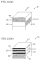
- FIG. 12 schematically illustrates heat exchangers, wherein Fig. 12(A) shows a conventional heat exchanger and Fig. 12(B), a heat exchanger using a honeycomb structure having slits obtainable according to the present method.
- the method for manufacturing a honeycomb structure having slits according to the present invention is characterized in that, at the step of extruding the honeycomb structure, slits are formed by protruding the slit forming member toward the molded article during a step of extruding a honeycomb structure having slits. Fine slits may be formed by cutting or grinding only the targeted cell array or arrays according to the present method for manufacturing a honeycomb structure having slits, and this method is a simple one fitted to mass production. The present invention will be described in detail below.
- a first feature of the method for manufacturing a honeycomb structure having slits according to the present invention is to form slits during the step of extruding the honeycomb structure.
- a relatively soft green molded article is used for the formation of the slits instead of a hardened and densified, dried, and/or fired article.
- the formation of slits may be done simultaneously with the extrusion of a honeycomb structure body, time and labor required for manufacturing a honeycomb structure having slits may be saved, compared with separate slit forming method using a dried or a fired article according to the conventional method.
- the firing of the molded article and that of sealing members 25 may be made simultaneously.
- one may save one step for firing, compared with the case when slits are formed in a fired article.
- this method is not only a highly productive method, but also a method fitted to mass production.
- the firing of a molded article and that of sealing members can be done at the same time if the cell array(s) in which slits are to be formed is sealed prior to firing. In this case, however, it is not preferable since the removal of the chips formed during forming the slits or the like becomes difficult because the formation of slits is done after sealing.
- a second feature of a method for manufacturing a honeycomb structure having slits according to the present invention is to form slits by boring slits in a molded article during a time when a molded article is being extruded.
- the molded article is less susceptible to the impacts of compression or deformation during extrusion and the drying and firing of the molded article than separate slit forming method after extrusion.
- a third feature of a method for manufacturing a honeycomb structure having slits according to the present invention is to form slits protruding a slit forming member toward a molded article during the extruding step of a honeycomb structure body.
- Slits may be formed even in the central part of the structure according to the present method. This is because the formation of slits having any desired length in any desired position of a structure in its lengthwise direction may be done by adjusting the position of the molded article during the extrusion step and the timing for protruding the slit forming member.
- the problem of weakened mechanical strength at the two ends of the structure or increased compression or deformation can be averted, and thus this method may be applicable, with a particular suitableness, to the manufacture of a honeycomb structure having slits for a solid-liquid separation filter.
- slits 34 would be formed all over the external circumference of the molded article 32 as illustrated in Fig. 3.
- the mechanical strength of the molded article 32 is weakened, and breakage during extrusion of a molded article or handling the molded article or breakage due to stress concentration at the time of drying or firing becomes inevitable.
- Specific methods of monitoring the position of the molded article being extruded include: (1) direct monitoring of the position of the molded article with a sensor or the like, and (2) indirect monitoring comprising by measuring and converting any one factors inclusive of the quantity, duration time for extrusion and the like at the time of extruding a puddled ceramic mixture.
- the slit forming member may be protruded along the cell array(s) in which slits are to be formed of the molded article being extruded.
- the slit forming member may constitute a part of the extruding die, and slits may be formed by extrusion. Where the slit forming member is protruded immediately after the cell formation, slits may be formed by cutting specified portion(s) of the molded article being extruded.
- a slit forming member may as well be protruded along a plurality of mutually adjoining cell arrays to simultaneously cut or ground the plurality of cell arrays.
- the depth of the slits is not particularly limited, and it may be provided only in the vicinity of the external face of the structure or, in some cases, go through the structure. Further, a plurality of slits can as well be formed in the lengthwise direction of one cell array of the honeycomb structure or in not just one but a plurality of cell arrays.
- the length of the slits is not particularly limited, the total slit length in any one cell array should preferably be not more than 1/3 of the overall length of the structure in view of mechanical strength. Where a plurality of slits are to be formed in one cell array, it is preferable to keep the spacing between the respective slits at 1/10 of the length of the slit or more.
- the length of slits is not necessarily equal, but, for instance, the length may be short in the internal portion of the structure and increased in the external portion thereof.
- Such a configuration is useful when the structure is used as a solid-liquid separation filter, because it enables the filtrate to be efficiently discharged to external space. This is because, in the case of a solid-liquid separation filter, the amount of the filtrate discharged through slit is increased due to the join of the filtrate from many cells at a peripheral portion of the structure, while the amount of the filtrate discharged through slits in the internal portion thereof is not so much.
- the method for manufacturing a honeycomb structure having slits according to the present invention can be carried out by using an apparatus for manufacturing a honeycomb structure having slits, which comprises, an extruder having an extruding die for a honeycomb structure, and a slit forming member arranged in the vicinity of the extruding die and being movable along specified cell array(s) of an extruded article in which slits are to be formed.
- an extruder is a molding machine that is provided with an extruder and an extruding die and can consecutively provide a molded article of a desired shape by extruding a molding material charged to the extruder from the extruding die.
- a conventional known extruder can be suitably used such as a single-shaft, double-shaft or multi-shaft screw extruder or a plunger extruder.
- the extruding die in the apparatus for manufacturing a honeycomb structure having slits according to the present invention is required to have an internal wall corresponding to an external shape of a honeycomb structure, and a shape in which cell blocks 48 corresponding to many cells aligned in parallel as shown in Fig. 4. That is, it should have a shape complementary to a honeycomb structure to be extruded. Many cells are formed since the cell blocks 48 of the die block a molding material from being pushed forward from the back side (not shown) of the die shown in Fig. 4.
- a puddled mixture obtained by admixing a mixture comprising a ceramic powder, a binder, and a solvent, and optionally a surface active agent, a plasticizer or the like is used as a molding material.
- the slit forming member in the apparatus for manufacturing a honeycomb structure having slits according to the present invention is a member for forming slits in a green molded article which is being extruded.
- a slit forming member to be used for practicing the present invention is not required to have a hardness such as a bit onto which a high-speed steel edge is brazed or a grind stone to which diamond is electro-deposited. Indeed, it is not required to be a revolving body such as a grinder or a drill.
- any impact of compression or deformation at the time of extrusion or drying or firing of the molded article can be eliminated as much as possible. Furthermore, the positioning of the slit forming member relative to the targeted cell array may be easily facilitated.
- the positions of the cell arrays and the slits will match each other to enable fine slits to be accurately formed into the targeted cell array(s) alone.
- the slit forming member as long as it is installed in the vicinity of the extruding die, may be disposed so as to protrude either outwardly or inwardly toward the extruding die or even to protrude both outwardly and inwardly in some cases.
- the slit forming member protrudes outwardly toward the die, the slit forming member functions as a cutting edge, and slits are formed by cutting the specified array(s) after the formation of the cell.
- the slit forming member in the case where the slit forming member protrudes inwardly toward the die, the slit forming member constitutes a part of the extruding die, and it blocks a puddled mixture to be extruded in that part.
- slits are formed simultaneously at the time of extruding a honeycomb structure.
- slits may be formed only on the external wall of the honeycomb structure, or if the slit forming member 4 is installed following the cell blocks as shown in Fig. 1(B), slits 5 can be provided not only on the external wall 3a of, but also inside the honeycomb structure.
- the thickness of the slit forming member is equal to or less than the diameter of the cell pores not so as to break the cell wall with the slit forming member. In a case where a plurality of adjacent cell arrays are to be cut or ground simultaneously, it is preferable that the thickness thereof is such a thickness that the cell wall on the outermost row of the honeycomb structure is not broken thereby.
- the slit forming member should be rigid enough not to yield to the extruding pressure of a puddled mixture for forming honeycomb structure. This is because, if it is not rigid enough, the slit forming member may yield to the extruding pressure of the a puddled mixture and be deformed to invite such machining errors as breaking the adjacent cell arrays or cutting the cell wall.
- a honeycomb structure having a long shape in the extruding direction of a molded article such as a rectangular or a square shape is preferable because it makes the member rigid in that direction.
- a manufacturing method according to the present invention allows slits to be formed in any desired length by appropriately adjusting the position of the molded article during extrusion and the timing of protruding the slit forming member.
- the length of the slit forming member and that of the slit are identical. Therefore, as long as the aforementioned rigidity is secured, a pin-shaped slit forming member having no length in the extruding direction of the molded article can be used.
- edge shape of the slit forming member is not particularly limited, its sectional shape across the extruding direction of the molded article may be round, rectangular or wedged as illustrated in Fig. 5(A) through 5(C). Where the edge shape has corners, such as in a rectangular or wedged shape, it is preferable to have a taper or round shape at the corners to prevent them from developing cracks at the slit end when drying or firing the molded article.
- preferable tip sectional shapes across the protruding direction of the slit forming member include, as shown in Figs. 6(A) through 6(D), round, rectangular, semi-annular and wedged shapes.
- a tip sectional shape 41 across the protruding direction of the member it is preferable to match a tip sectional shape 41 across the protruding direction of the member to the external circumference of the molded article 42 as illustrated in Fig. 6(E), because it would enable the edge (tip face) of the slit forming member to cut into the molded article simultaneously, and thereby the shape of the slit ends is formed accurately. Since the slit forming member is protruded toward the molded article being extruded according the present invention, if a tip sectional shape 43 does not match the molded article 42 as shown in Fig. 6(F), the part of the edge on the left of the drawing will firstly cut into the molded article. Therefore, the end of the slits would be formed in a steep shape, and not accurately in the intended shape.
- the slit forming member is to be installed so as to protrude out of the extruding die, it is preferable that the slit forming member is a J-shaped bit.
- a slit is cut into the molded article being extruded, resulting in the problem that the generated chip sticks to the slit forming member and thereby increases the machining resistance of the edge.
- An increase in the machining resistance of the edge is undesirable because it would distort the slit shape or break cell wall on both sides of the slits.
- a J-shaped bit 45 has a hollow part 46 ahead in the extruding direction of the molded article as illustrated in Fig. 6(G), this type of the slit forming member is preferable since the hollow part 46 can scrape and remove chips.
- the slit forming member is to protrude inwardly toward the die, as it constitutes part of the extruding die and forms slits during extrusion step, no such problem arises.
- the slit forming member may as well be installed so as to protrude from only one side of the molded article. In this case, however, the greater length and the resultant greater flexibility of the slit forming member might invite distortion of the slit or break the cell walls on both sides of the slits.
- Adjustment of the protrusion, retracting and protruding depth of the slit forming member may be done with a hydraulic cylinder or an electromotive cylinder besides an air cylinder.
- a stopper 54 may be provided as illustrated in Fig. 7.
- the manufacturing apparatus it is preferable for the manufacturing apparatus according to the present invention to have monitoring means for monitoring the position of the molded article being extruded and control means for controlling the actions of the slit forming member based on the monitoring data, because slits of any desired length could then be formed in any desired position in the lengthwise direction of the molded article by controlling the actions such as protrusion and retracting of the slit forming member according to the monitored position.
- the monitoring means may be a sensor for monitoring the position of the molded article, a sensor for monitoring the extruded volume of a puddled mixture for a honeycomb body or a timer for monitoring the duration period of the extrusion of the puddled mixture.
- this apparatus can control the movement of the slit forming member so as to protrude the slit forming member according to signals detected by sensors S1 and S3, and retract the member according to signals detected by sensors S2, based on the result of monitoring the tip position of a molded article with a plurality of sensors S1, S2, S3, and S4 consecutively arranged in the direction of extruding the slit forming member.
- the manufacturing apparatus 61 can provide a molded article in the vicinity of each of whose ends slits are formed. After the forming of slits, the extrusion of the puddled mixture is stopped in response to a detection signal from the sensor S5, and the terminal part of the molded article is cut off near a die 63.
- the manufacturing method according to the present invention is intended to use for the manufacture of a honeycomb structure having slits and having a plurality of arrays of numerous cells aligned in parallel. More specifically, for that of what has a plurality of "arrays of cells" in which the many cells in each array are not formed at random, but arranged in parallel in at least one direction of the honeycomb structure when viewed from the cell opening faces of the structure.
- any type of a honeycomb body may be manufactured by applying the manufacturing method according to the present invention; that is, irrespective of its overall shape, its size, its cell shape, diameter of its cell pore, its spacing of cells (cell wall thickness) or the like, and materials to be used for manufacturing the honeycomb body.
- the base can be tubular having a circular, square, rectangular or hexagonal sectional shape, and the material of the base may be selected as appropriate for the particular purpose out of various ceramic materials including alumina, titania, mullite, zirconia, cordierite, and any mixture of them.
- the shape of individual cells can be circular, rectangular, pentagonal or hexagonal, and in some cases even a plurality of cell shapes can be formed in combination by using cell blocks such as the one illustrated in Fig. 4.
- the shape of the cells of the cell arrays in which the slits are to be formed is a rectangular shape. This is because the slit forming member can move forwards easily along the internal wall of cells, thereby machining errors such as breaking adjacent cell arrays or cutting cell walls are prevented, in a case of a honeycomb body having rectangular cells whose internal walls are linearly configured relative to the protruding direction of the slit forming member.
- a honeycomb structure having slits can be used particularly suitably as a solid-liquid separation filter.
- a solid-liquid separation filter can be produced by drying a green honeycomb molded article produced by the manufacturing method according to the present invention, firing the resultant after sealing the cell opening faces of the slit-formed cell arrays thereof, and, in case of need, forming further ceramic filtering diaphragm on the internal walls of cells other than the cells in which the slits have been formed by dipping or the like.
- a honeycomb structure having slits according to the present invention may be usable as a heat exchanger.
- a plurality of honeycomb structures are crossing and stacking each other as a block 102 to form a heat exchanger 101 by using the cells 105 thereof directly as a heat path, as is illustrated in Fig. 12(A).
- a heat exchanger 103 may be constituted of only a single body structure by using cell arrays having slits 104 and being sealed with a sealing member 106 at their ends, and other arrays of cells 105 as crossing heat paths, respectively.
- the manufacturing method according to the present invention is advantageous in that such a heat exchanger can be integrally manufactured thereby.
- a puddled mixture formed by admixing alumina powder of 150 m in average grain size, an organic binder and water was used as the molding material.
- a plunger extruder was used, and as the extruding die was used a hollow round one of 180 mm in inside diameter, in whose hollow part were arranged hexagonal cell blocks of 3 mm in the across flat length at a 3.6 mm pitch.
- This extruding die can give a honeycomb molded article in which about 2000 cells are formed.
- the extrusion length of the molded article was set to 1000 mm.
- the groove widths of the slits were measured after drying the respective molded article in which slits had been formed.
- slits were formed into the dried article, and the groove widths of the slits were immediately measured thereafter. Groove widths of not less than 1.5 mm and within 2.5 mm were marked with o ⁇ , ones over 2.5 mm or not more than 3.0 mm, with ⁇ , and others, with ⁇ .
- Slits were formed in a honeycomb structure at the extrusion step, using a manufacturing apparatus 1 shown in Fig. 1(B), which was equipped with a plate 4 having a width of 2.4 mm and a length of 6.7 mm as a slit forming member.
- the slit forming member was installed so as to protrude within an extruding die 2, and from both sides of a molded article 3 inwardly toward a molded article 3. The results are shown in Tables 1 and 2.
- Slits were formed at the extrusion step by using a manufacturing apparatus 71 shown in Fig . 9, equipped with a pin 74 having a diameter of 2.4 mm as a slit forming member.
- the slit forming members was installed so as to protrude within an extruding die 72, and from both sides of a molded article 73 inwardly toward a molded article 73. The results are shown in Tables 1 and 2.
- Slits 85 were formed at the extrusion step by using a manufacturing apparatus 81 in Fig. 10, equipped with a J-shaped bit 84 having a width of 2.4 mm as a slit forming member.
- the slit forming member was installed so as to protrude outwardly toward an extruding die 82, but from both sides of a molded article 83 toward inwardly toward a molded article 83.
- Tables 1 and 2 The results are shown in Tables 1 and 2.
- Embodiments 1 through 3 although a slight contraction of slit width was observed after drying Embodiments 1 and 2, there was no problem in practical use, and the accuracy of groove width was satisfactory in both cases. In Comparative Example 1, the accidental cutting of cell walls in some cases almost broke the cell walls, and the accuracy of groove width was poor.
- Embodiments 1 through 3 required no particular manual machining task as an automated manufacturing apparatus formed slits
- the work on Comparative Example 1 was troublesome, involving marking on the external face of the structure and cutting while directly watching the structure with naked eyes.
- Comparative Example 1 involved problems in all respects including machining accuracy, machining time, tool durability, workability and cost.
- the manufacturing method and the manufacturing apparatus according to the present invention permit accurate forming of fine slits to cut or grind the targeted cell array(s) alone and moreover are suitably applicable to mass production.
- a method for manufacturing a honeycomb structure having slits which permits accurate forming of fine slits to cut or grind a targeted cell array alone and moreover is suitable for application to mass production, is to be provided. It is a method for manufacturing a honeycomb structure having slits and a plurality of arrays of numerous cells aligned in parallel; the slits communicating with external space and being formed along the arrays.
- Slits 5 are formed by protruding a slit forming member 4 toward a molded article 3 during the step of extruding the honeycomb structure.
Landscapes
- Engineering & Computer Science (AREA)
- Chemical & Material Sciences (AREA)
- Mechanical Engineering (AREA)
- Chemical Kinetics & Catalysis (AREA)
- Ceramic Engineering (AREA)
- Combustion & Propulsion (AREA)
- General Engineering & Computer Science (AREA)
- Toxicology (AREA)
- Health & Medical Sciences (AREA)
- Structural Engineering (AREA)
- Materials Engineering (AREA)
- Organic Chemistry (AREA)
- Press-Shaping Or Shaping Using Conveyers (AREA)
- Devices For Post-Treatments, Processing, Supply, Discharge, And Other Processes (AREA)
- Catalysts (AREA)
Applications Claiming Priority (2)
| Application Number | Priority Date | Filing Date | Title |
|---|---|---|---|
| JP2000046530 | 2000-02-23 | ||
| JP2000046530A JP4298116B2 (ja) | 2000-02-23 | 2000-02-23 | スリット付きハニカム構造体の製造方法及び製造装置 |
Publications (2)
| Publication Number | Publication Date |
|---|---|
| EP1128031A1 true EP1128031A1 (fr) | 2001-08-29 |
| EP1128031B1 EP1128031B1 (fr) | 2002-12-11 |
Family
ID=18568924
Family Applications (1)
| Application Number | Title | Priority Date | Filing Date |
|---|---|---|---|
| EP01102276A Expired - Lifetime EP1128031B1 (fr) | 2000-02-23 | 2001-01-31 | Méthode pour la fabrication d'une structure en nid d'abeilles comprenant des fentes et appareil pour la fabrication de celle-ci |
Country Status (4)
| Country | Link |
|---|---|
| US (2) | US6723262B2 (fr) |
| EP (1) | EP1128031B1 (fr) |
| JP (1) | JP4298116B2 (fr) |
| DE (1) | DE60100062T2 (fr) |
Cited By (5)
| Publication number | Priority date | Publication date | Assignee | Title |
|---|---|---|---|---|
| EP1508402A1 (fr) * | 2002-03-29 | 2005-02-23 | Ngk Insulators, Ltd. | Procede de fabrication de structure en nid d'abeille |
| WO2006056211A3 (fr) * | 2004-11-29 | 2006-07-06 | Stobbe R & D Aps | Dispositif de filtrage pour l'elimination de particules de gaz d'echappement |
| EP1864774A1 (fr) * | 2006-06-05 | 2007-12-12 | Ibiden Co., Ltd. | Méthode et appareil pour la coupe d'une structure en nid d'abeilles |
| WO2009023143A1 (fr) * | 2007-08-10 | 2009-02-19 | Corning Incorporated | Dispositif de traitement de fluide ayant une structure en nid d'abeilles à couches multiples, et procédé de fabrication |
| US7645427B2 (en) * | 2002-10-10 | 2010-01-12 | Ngk Insulators, Ltd. | Honeycomb structure, manufacturing method of the structure, and exhaust gas purification system using the structure |
Families Citing this family (21)
| Publication number | Priority date | Publication date | Assignee | Title |
|---|---|---|---|---|
| NO316475B1 (no) * | 2000-09-22 | 2004-01-26 | Nordic Exchanger Technology As | Varmevekslerelement |
| US6852291B1 (en) * | 2000-10-11 | 2005-02-08 | Innovadyne Technologies, Inc. | Hybrid valve apparatus and method for fluid handling |
| JP4685444B2 (ja) * | 2002-05-24 | 2011-05-18 | 日本碍子株式会社 | ハニカムフィルタの製造方法 |
| JP4155772B2 (ja) * | 2002-08-16 | 2008-09-24 | 日本碍子株式会社 | スリット付きハニカム構造体、ハニカム構造体、及びハニカム構造体の製造方法 |
| JP4358538B2 (ja) * | 2003-03-17 | 2009-11-04 | 日本碍子株式会社 | セラミックフィルタ |
| JP2004275907A (ja) * | 2003-03-17 | 2004-10-07 | Ngk Insulators Ltd | セラミックフィルタ |
| CN100377761C (zh) * | 2003-03-24 | 2008-04-02 | 日本碍子株式会社 | 陶瓷过滤器 |
| JP2004306020A (ja) * | 2003-03-24 | 2004-11-04 | Ngk Insulators Ltd | セラミックフィルタ |
| SE527456C2 (sv) * | 2003-07-28 | 2006-03-14 | Sandvik Intellectual Property | Förfarande och anordning för tillverkning genom extrusion av roterande verktyg för spånavskiljande bearbetning och verktyg |
| US7601194B2 (en) * | 2003-09-25 | 2009-10-13 | Corning Incorporated | Asymmetric honeycomb wall-flow filter having improved structural strength |
| JP2006006998A (ja) * | 2004-06-22 | 2006-01-12 | Ngk Insulators Ltd | セラミックフィルタ |
| FR2883490B1 (fr) * | 2005-03-22 | 2007-12-14 | Syngas Entpr Unipersonnelle A | Unite de traitement catalytique a chaud des gaz |
| JP2007237053A (ja) * | 2006-03-07 | 2007-09-20 | Ngk Insulators Ltd | 濾過器及び濾過器の逆洗方法 |
| JP5144075B2 (ja) * | 2006-03-30 | 2013-02-13 | 日本碍子株式会社 | ハニカム構造体及びその製造方法 |
| EP2067589B1 (fr) * | 2006-09-28 | 2012-04-11 | Hitachi Metals, Ltd. | Procédé et appareil pour fabriquer une structure en nid d'abeilles céramique |
| JP5475953B2 (ja) * | 2008-01-24 | 2014-04-16 | 日本碍子株式会社 | 穴あきハニカム構造体の製造方法 |
| JP5360051B2 (ja) * | 2008-03-28 | 2013-12-04 | 日立金属株式会社 | セラミックハニカム構造体成形用金型 |
| JP5162509B2 (ja) * | 2009-03-24 | 2013-03-13 | 日本碍子株式会社 | ハニカム成形体へのスリット形成方法 |
| JPWO2013038564A1 (ja) * | 2011-09-16 | 2015-03-23 | イビデン株式会社 | ハニカム構造体の製造方法および排ガス浄化装置の製造方法 |
| NO340556B1 (no) * | 2014-05-30 | 2017-05-08 | Pleat As | Anordning for varmeveksling |
| FR3074060B1 (fr) | 2017-11-30 | 2023-04-28 | Saint Gobain Ct Recherches | Structure filtrante membranaire monolithique |
Citations (2)
| Publication number | Priority date | Publication date | Assignee | Title |
|---|---|---|---|---|
| EP0017686A1 (fr) * | 1979-04-21 | 1980-10-29 | Ngk Insulators, Ltd. | Procédé de fabrication d'une matrice pour mouler par extrusion une charge de matière céramique en un corps à structure en nid d'abeilles et une matrice fabriquée par ce procédé |
| EP0452125A2 (fr) * | 1990-04-12 | 1991-10-16 | Ngk Insulators, Ltd. | Elément chauffant et dispositif de catalyseur |
Family Cites Families (12)
| Publication number | Priority date | Publication date | Assignee | Title |
|---|---|---|---|---|
| US3683059A (en) * | 1970-07-17 | 1972-08-08 | Fmc Corp | Method for making reticulated structures |
| IT1157134B (it) * | 1982-12-10 | 1987-02-11 | Saiag Spa | Procedimento ed apparecchiatura per realizzare mediante estrusione continua un trafilato in particolare una guarnizione di tenuta per carrozzerie di autoveicoli presentante successivi tratti di lunghezze predeterminate aventi ciascuno una rispettiva sezione prestabilita e trafilato ottenuto con tale procedimento |
| FR2597026B1 (fr) * | 1986-04-11 | 1988-12-09 | Trotignon Jean Pierre | Dispositif de fabrication d'une plaque alveolaire, plaque alveolaire en resultant |
| US4781831A (en) | 1986-12-19 | 1988-11-01 | Goldsmith Robert L | Cross-flow filtration device with filtrate flow conduits and method of forming same |
| JPH0661816B2 (ja) * | 1988-03-24 | 1994-08-17 | 鬼怒川ゴム工業株式会社 | 異形押出成形用口金構造 |
| US5149475A (en) * | 1988-07-28 | 1992-09-22 | Ngk Insulators, Ltd. | Method of producing a honeycomb structure |
| US5240663A (en) * | 1989-09-20 | 1993-08-31 | Sulzer Brothers Limited | Method,apparatus and extrusion nozzle for producing a member from extrudable material |
| DE4324347A1 (de) | 1992-07-23 | 1994-01-27 | Noritake Co Ltd | Monolithischer Keramikfilter |
| US5447670A (en) * | 1993-04-28 | 1995-09-05 | Toyoda Gosei Co., Ltd. | Method of and apparatus for forming weather strip by extrusion |
| WO1996028264A1 (fr) * | 1995-03-16 | 1996-09-19 | Mitsubishi Aluminum Co., Ltd. | Matrice a extrusion a section variable et technique d'extrusion avec ce type de matrice |
| JP3635780B2 (ja) * | 1996-04-08 | 2005-04-06 | 株式会社デンソー | ハニカム構造体の成形装置及び成形方法 |
| JP2002283327A (ja) * | 2001-03-28 | 2002-10-03 | Ngk Insulators Ltd | ハニカム構造体成形装置及び成形方法 |
-
2000
- 2000-02-23 JP JP2000046530A patent/JP4298116B2/ja not_active Expired - Fee Related
-
2001
- 2001-01-24 US US09/768,891 patent/US6723262B2/en not_active Expired - Fee Related
- 2001-01-31 DE DE60100062T patent/DE60100062T2/de not_active Expired - Lifetime
- 2001-01-31 EP EP01102276A patent/EP1128031B1/fr not_active Expired - Lifetime
-
2003
- 2003-11-12 US US10/706,063 patent/US20040142055A1/en not_active Abandoned
Patent Citations (2)
| Publication number | Priority date | Publication date | Assignee | Title |
|---|---|---|---|---|
| EP0017686A1 (fr) * | 1979-04-21 | 1980-10-29 | Ngk Insulators, Ltd. | Procédé de fabrication d'une matrice pour mouler par extrusion une charge de matière céramique en un corps à structure en nid d'abeilles et une matrice fabriquée par ce procédé |
| EP0452125A2 (fr) * | 1990-04-12 | 1991-10-16 | Ngk Insulators, Ltd. | Elément chauffant et dispositif de catalyseur |
Cited By (10)
| Publication number | Priority date | Publication date | Assignee | Title |
|---|---|---|---|---|
| EP1508402A1 (fr) * | 2002-03-29 | 2005-02-23 | Ngk Insulators, Ltd. | Procede de fabrication de structure en nid d'abeille |
| EP1508402A4 (fr) * | 2002-03-29 | 2006-03-15 | Ngk Insulators Ltd | Procede de fabrication de structure en nid d'abeille |
| US7309277B2 (en) | 2002-03-29 | 2007-12-18 | Ngk Insulators, Ltd. | Method of manufacturing honeycomb structural body |
| US7645427B2 (en) * | 2002-10-10 | 2010-01-12 | Ngk Insulators, Ltd. | Honeycomb structure, manufacturing method of the structure, and exhaust gas purification system using the structure |
| WO2006056211A3 (fr) * | 2004-11-29 | 2006-07-06 | Stobbe R & D Aps | Dispositif de filtrage pour l'elimination de particules de gaz d'echappement |
| EP1864774A1 (fr) * | 2006-06-05 | 2007-12-12 | Ibiden Co., Ltd. | Méthode et appareil pour la coupe d'une structure en nid d'abeilles |
| EP1880817A1 (fr) * | 2006-06-05 | 2008-01-23 | Ibiden Co., Ltd. | Méthode pour la coupe d'une structure en nid d'abeilles |
| EP1880818A1 (fr) * | 2006-06-05 | 2008-01-23 | Ibiden Co., Ltd. | Méthode pour la coupe d'une structure en nid d'abeilles |
| WO2009023143A1 (fr) * | 2007-08-10 | 2009-02-19 | Corning Incorporated | Dispositif de traitement de fluide ayant une structure en nid d'abeilles à couches multiples, et procédé de fabrication |
| US8007731B2 (en) | 2007-08-10 | 2011-08-30 | Corning Incorporated | Fluid treatment device having a multiple ceramic honeycomb layered structure |
Also Published As
| Publication number | Publication date |
|---|---|
| US6723262B2 (en) | 2004-04-20 |
| JP2001232615A (ja) | 2001-08-28 |
| DE60100062T2 (de) | 2003-10-09 |
| JP4298116B2 (ja) | 2009-07-15 |
| EP1128031B1 (fr) | 2002-12-11 |
| DE60100062D1 (de) | 2003-01-23 |
| US20040142055A1 (en) | 2004-07-22 |
| US20010020756A1 (en) | 2001-09-13 |
Similar Documents
| Publication | Publication Date | Title |
|---|---|---|
| EP1128031B1 (fr) | Méthode pour la fabrication d'une structure en nid d'abeilles comprenant des fentes et appareil pour la fabrication de celle-ci | |
| EP2064028B1 (fr) | Structures alvéolaires apprêtées à l'endroit et leurs procédés de fabrication | |
| EP1772242B1 (fr) | Filière pour l'extrusion et procédé de fabrication de corps poreux en céramique | |
| US4428758A (en) | Solid particulate filters | |
| EP1340530B1 (fr) | Filtre en nid d'abeille et son procede de fabrication | |
| EP1974884B1 (fr) | Procédé de fabrication d'un élément structuré en nid d'abeille | |
| US9962770B2 (en) | Method for producing ceramic honeycomb body | |
| US6290837B1 (en) | Method for machining slots in molding die | |
| EP1964655B1 (fr) | Procédé de fabrication d'un élément structuré en nid d'abeille | |
| EP1724056B1 (fr) | Méthode pour la fabrication d'une structure en nid d'abeilles | |
| US4557682A (en) | Apparatus for fabrication of solid particulate filters | |
| EP2944366A2 (fr) | Structure en nid d'abeille | |
| EP2116347B1 (fr) | Procédé de fabrication d'une structure en nid d'abeille hermétique | |
| US8128395B2 (en) | Honeycomb segment-forming die and method for manufacturing honeycomb structure | |
| EP2484504B1 (fr) | Méthode d'une fabrication d'une structure en nid d'abeilles | |
| JP4222586B2 (ja) | スリット付きハニカム構造体の製造方法 | |
| EP2481542A1 (fr) | Structure de nid d'abeilles et son procédé de fabrication | |
| US11135739B2 (en) | Manufacturing method of honeycomb structure | |
| JP3745504B2 (ja) | ハニカム構造体押出用ダイスおよびその製造方法 | |
| EP3714139B1 (fr) | Corps en nid d'abeilles à stockage élevé de cendres, à motifs fixes et filtres à particules | |
| JPH08112809A (ja) | 押出し成形金型 | |
| US20170259460A1 (en) | Manufacturing method of honeycomb structure forming die, and honeycomb structure forming die | |
| JP2010221588A (ja) | ハニカムフィルタの目詰まり除去治具及び除去治具を用いた目詰まり除去方法 |
Legal Events
| Date | Code | Title | Description |
|---|---|---|---|
| PUAI | Public reference made under article 153(3) epc to a published international application that has entered the european phase |
Free format text: ORIGINAL CODE: 0009012 |
|
| AK | Designated contracting states |
Kind code of ref document: A1 Designated state(s): DE FR GB Kind code of ref document: A1 Designated state(s): AT BE CH CY DE DK ES FI FR GB GR IE IT LI LU MC NL PT SE TR |
|
| AX | Request for extension of the european patent |
Free format text: AL;LT;LV;MK;RO;SI |
|
| 17P | Request for examination filed |
Effective date: 20010808 |
|
| 17Q | First examination report despatched |
Effective date: 20011031 |
|
| GRAG | Despatch of communication of intention to grant |
Free format text: ORIGINAL CODE: EPIDOS AGRA |
|
| AKX | Designation fees paid |
Free format text: DE FR GB |
|
| GRAG | Despatch of communication of intention to grant |
Free format text: ORIGINAL CODE: EPIDOS AGRA |
|
| GRAH | Despatch of communication of intention to grant a patent |
Free format text: ORIGINAL CODE: EPIDOS IGRA |
|
| GRAH | Despatch of communication of intention to grant a patent |
Free format text: ORIGINAL CODE: EPIDOS IGRA |
|
| GRAA | (expected) grant |
Free format text: ORIGINAL CODE: 0009210 |
|
| AK | Designated contracting states |
Kind code of ref document: B1 Designated state(s): DE FR GB |
|
| REG | Reference to a national code |
Ref country code: GB Ref legal event code: FG4D |
|
| REF | Corresponds to: |
Ref document number: 60100062 Country of ref document: DE Date of ref document: 20030123 |
|
| ET | Fr: translation filed | ||
| PLBE | No opposition filed within time limit |
Free format text: ORIGINAL CODE: 0009261 |
|
| STAA | Information on the status of an ep patent application or granted ep patent |
Free format text: STATUS: NO OPPOSITION FILED WITHIN TIME LIMIT |
|
| 26N | No opposition filed |
Effective date: 20030912 |
|
| PGFP | Annual fee paid to national office [announced via postgrant information from national office to epo] |
Ref country code: FR Payment date: 20101221 Year of fee payment: 11 |
|
| PGFP | Annual fee paid to national office [announced via postgrant information from national office to epo] |
Ref country code: GB Payment date: 20101215 Year of fee payment: 11 |
|
| PGFP | Annual fee paid to national office [announced via postgrant information from national office to epo] |
Ref country code: DE Payment date: 20110131 Year of fee payment: 11 |
|
| GBPC | Gb: european patent ceased through non-payment of renewal fee |
Effective date: 20120131 |
|
| REG | Reference to a national code |
Ref country code: FR Ref legal event code: ST Effective date: 20120928 |
|
| PG25 | Lapsed in a contracting state [announced via postgrant information from national office to epo] |
Ref country code: GB Free format text: LAPSE BECAUSE OF NON-PAYMENT OF DUE FEES Effective date: 20120131 Ref country code: DE Free format text: LAPSE BECAUSE OF NON-PAYMENT OF DUE FEES Effective date: 20120801 |
|
| REG | Reference to a national code |
Ref country code: DE Ref legal event code: R119 Ref document number: 60100062 Country of ref document: DE Effective date: 20120801 |
|
| PG25 | Lapsed in a contracting state [announced via postgrant information from national office to epo] |
Ref country code: FR Free format text: LAPSE BECAUSE OF NON-PAYMENT OF DUE FEES Effective date: 20120131 |