EP1127997B1 - Treppe für einen Treppenturm - Google Patents
Treppe für einen Treppenturm Download PDFInfo
- Publication number
- EP1127997B1 EP1127997B1 EP20010100477 EP01100477A EP1127997B1 EP 1127997 B1 EP1127997 B1 EP 1127997B1 EP 20010100477 EP20010100477 EP 20010100477 EP 01100477 A EP01100477 A EP 01100477A EP 1127997 B1 EP1127997 B1 EP 1127997B1
- Authority
- EP
- European Patent Office
- Prior art keywords
- slot
- slots
- staircase
- string according
- rung
- Prior art date
- Legal status (The legal status is an assumption and is not a legal conclusion. Google has not performed a legal analysis and makes no representation as to the accuracy of the status listed.)
- Expired - Lifetime
Links
- 239000000725 suspension Substances 0.000 claims description 13
- 230000009194 climbing Effects 0.000 description 1
- 230000001419 dependent effect Effects 0.000 description 1
- 238000004519 manufacturing process Methods 0.000 description 1
Images


Classifications
-
- E—FIXED CONSTRUCTIONS
- E04—BUILDING
- E04F—FINISHING WORK ON BUILDINGS, e.g. STAIRS, FLOORS
- E04F11/00—Stairways, ramps, or like structures; Balustrades; Handrails
- E04F11/02—Stairways; Layouts thereof
- E04F11/022—Stairways; Layouts thereof characterised by the supporting structure
- E04F11/025—Stairways having stringers
Definitions
- the present invention relates to a staircase for the stair tower based on a modular scaffolding.
- the present invention further relates to the stair stringers and the associated steps.
- Scaffolding is nowadays increasingly being equipped with a stair tower, which allows workers to reach the different levels of the scaffolding and be transported by the loads.
- the stairs of such a stair tower must be made massive so that they can be sufficiently loaded. This massive design has the disadvantage that the stairs themselves or the items from which they are mounted are often heavy and therefore unwieldy.
- the stair string invention has an upper flange and a lower flange, which are preferably interconnected by two end posts.
- rungs are attached between the upper belt and the lower belt, to which the steps are attached.
- these rungs have at least two slots which reversibly receive the attachment bolts of a step.
- the slots can be attached to the rungs in any manner known to those skilled in the art.
- slotted plates are welded to the rungs, are incorporated in the slots.
- the slots in the rungs punched, milled or stamped.
- a slit pockets is pressed into the rung, in which the slots are incorporated.
- each slot has an opening through which the Ein vonbolzen a matching to the staircase according to the invention staircase step is inserted into the slots. Through this opening, the step can also be solved again by the slotted sheet.
- a slot is arranged parallel to the longitudinal central axis of the rung and the other slot at an angle of 25 ° -155 °, preferably 45 ° -135 ° with respect to the longitudinal center axis of the rung. More preferably, the angle is 85 ° -95 °, most preferably 90 °.
- the slot is straight. Also preferably, at least one slot is L-shaped.
- the slots are 10 to 30 mm long and have a width of 8 to 20 mm.
- the stair string according to the invention has a low weight and is easy to manufacture. There must be no additional locks are provided to secure a step securely to the stair string invention.
- a rectangular step which has two suspension bolts on the circumference on two opposite sides.
- suspension bolts can have any shape. However, they preferably have a cylindrical part, on whose one end face a disc is attached, which has a larger diameter than the cylindrical part.
- the Ein rehabilitationbolzen a step, which is attached to the stair string invention, from is pulled out of the slot.
- the diameter of the cylindrical part is 6 to 18 mm and its length 10 to 30 mm.
- Another object of the present invention is a staircase, which consists of the invention and the stairs staircase invention.
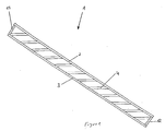
- FIG. 1 shows the staircase cheek according to the invention.
- Figure 2 shows a rung of the staircase cheek invention.
- FIG. 2 also shows how a step is fastened to the rung.
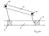
- Figure 2a shows another embodiment of the rung of the stair string invention.
- FIG. 2a also shows how a step is fastened to the rung.
- Figure 3 shows slots punched into the rung.
- Figure 4 shows rungs with slit pockets, in which the slots are incorporated.
- FIG. 5 shows the step according to the invention.
- the stair string invention 1 is shown. It has a lower flange 3 and a top flange 2.
- the straps are connected by the posts 12, 13.
- sprouts 4 are welded.
- FIG. 2 shows a rung 4 of the staircase cheek according to the invention.
- two slotted plates 5, 6 are welded, wherein the slotted plate 6 is mounted in the vicinity of the lower flange and the slotted plate 5 in the vicinity of the upper flange.
- the slotted plates 5, 6 each have a slot 8,9, the so in the slotted plates 5, 6 is mounted, that each slot 8.9 on one side has an opening 11,12 through which the suspension bolts 10 of the step 7 can be inserted into the slot The openings point in the direction of the lower flange.
- the slotted plates are arranged so that the longitudinal central axis of the slot 8 is arranged parallel to the longitudinal center axis of the rung, while the longitudinal center axis 9 of the slotted plate 6 is arranged at an angle of 135 ° relative to the longitudinal center axis of the rung.
- This configuration has the advantage that a craftsman when climbing the stairs can not trigger the stairs.
- FIG. 2 is also shown by arrows, as the step 7 is mounted on the stair string 1.
- the suspension bolts 10 are inserted into the slots 8, 9 and then pulled down or pressed down the rear end of the step. Due to the arrangement of the slot 9 of the suspension bolt 10 is automatically pressed to the end of the slot 8. The same applies to the dismantling. By lifting the step in the rear area the suspension bolts 10 are pulled out of the slots 8, 9.
- a rung is shown, in which the slots are punched into the rung.
- the slot 9, which is located in the vicinity of the lower flange, is arranged in the present case at an angle of 90 ° relative to the longitudinal center axis of the rung.
- the slot 8 is L-shaped. This configuration prevents in particular that the step can be started.
- FIG. 4 shows a rung in which slot pockets are pressed into the side wall of the rung into which the slots are worked.
- FIG. 5 shows the step according to the invention. It has two suspension bolts each on the narrow sides.
- the suspension bolts exist from a cylindrical part 13, on whose one end face a disc 14 is attached, which has a larger diameter than the cylindrical part 13. By this undercut slipping out of the suspension bolt is avoided from the slot.
Landscapes
- Engineering & Computer Science (AREA)
- Architecture (AREA)
- Civil Engineering (AREA)
- Structural Engineering (AREA)
- Steps, Ramps, And Handrails (AREA)
Description
- Die vorliegende Erfindung betrifft eine Treppe für den Treppenturm auf Basis eines Modulgerüstes. Die vorliegende Erfindung betrifft ferner die Treppenwangen und die dazugehörigen Treppenstufen.
- Gerüste werden heutzutage immer öfter mit einem Treppenturm ausgerüstet, durch den die Arbeiter auf die verschiedenen Ebenen des Gerüstes gelangen und durch den Lasten transportiert werden können. Die Treppen eines solchen Treppenturms müssen massiv ausgeführt werden, damit sie hinreichend belastet werden können. Diese massive Ausführung hat den Nachteil, daß die Treppe selbst oder die Einzelteile aus der sie montiert wird oftmals schwer und damit unhandlich sind.
- Es bestand deshalb die Aufgabe Treppenteile mit einem geringen Gewicht zur Verfügung zu stellen, die leicht montierbar sind.
- Die Aufgabe wird erfindungsgemäß durch eine Treppenwange gemäß Patentanspruch 1 gelöst. Bevorzugte Ausführungsformen sind in den abhängigen Ansprüchen 2-8 beansprucht.
- Die erfindungsgemäße Treppenwange weist einen Obergurt und einen Untergurt auf, die vorzugsweise durch zwei Endpfosten miteinander verbunden sind. Zwischen dem Obergurt und dem Untergurt sind außerdem Sprossen angebracht, an denen die Treppenstufen befestigt werden.
- Diese Sprossen weisen erfindungsgemäß mindestens zwei Schlitze auf, die die Einhängebolzen einer Treppenstufe reversibel aufnehmen.
- Die Schlitze können an den Sprossen in jeder dem Fachmann geläufigen Weise angebracht werden.
- Vorzugsweise werden jedoch an den Sprossen Schlitzbleche angeschweißt, in die Schlitze eingearbeitet sind. Ebenfalls bevorzugt werden die Schlitze in die Sprossen gestanzt, gefräst oder eingeprägt. Ebenfalls bevorzugt wird in die Sprosse eine Schlitztaschen gedrückt, in die die Schlitze eingearbeitet werden.
- Vorzugsweise weist jeder Schlitz eine Öffnung auf, durch die die Einhängebolzen einer zu der erfindungsgemäßen Treppenwange passenden Treppenstufe in die Schlitze einführbar ist. Durch diese Öffnung kann die Treppenstufe auch wieder von dem Schlitzblech gelöst werden.
- In einer bevorzugten Ausführungsform ist ein Schlitz parallel zu der Längsmittelachse der Sprosse und der andere Schlitz in einem Winkel von 25°-155°, vorzugsweise 45°-135° bezogen auf die Längsmittelachse der Sprosse angeordnet. Besonders bevorzugt beträgt der Winkel 85°-95°, ganz besonders bevorzugt 90°. Diese Anordnung hat den Vorteil, daß die Treppenstufen an den Treppenwangen leicht montiert und nicht losgetreten werden können.
- Vorzugsweise ist der Schlitz gerade. Ebenfalls bevorzugt ist mindestens ein Schlitz L-förmig.
- In einer bevorzugten Ausführungsform sind die Schlitze 10 bis 30 mm lang und haben eine Breite von 8 bis 20 mm.
- Die erfindungsgemäße Treppenwange weist ein geringes Gewicht auf und ist einfach herzustellen. Es müssen keine zusätzlichen Arretierungen vorgesehen werden, um eine Treppenstufe sicher an der erfindungsgemäßen Treppenwange zu befestigen.
- Ebenfalls Gegenstand der vorliegenden Erfindung ist eine rechteckige Treppenstufe, die am Umfang an zwei gegenüberliegenden Seiten zwei Einhängebolzen aufweist.
- Diese Einhängebolzen können eine beliebige Form haben. Vorzugsweise weisen sie jedoch einen zylindrischen Teil auf, an dessen einer Stirnseite eine Scheibe angebracht ist, die einen größeren Durchmesser aufweist als der zylindrische Teil. Durch diese Form der Einhängebolzen wird vermieden, daß die Einhängebolzen einer Treppenstufe, die an der erfindungsgemäßen Treppenwange befestigt ist, aus dem Schlitz herausgezogen wird. Vorzugsweise beträgt der Durchmesser des zylindrischen Teils 6 bis 18 mm und dessen Länge 10 bis 30 mm.
- Ein weiterer Gegenstand der vorliegenden Erfindung ist eine Treppe, die aus den erfindungsgemäßen Treppenwangen und aus den erfindungsgemäßen Treppenstufen besteht.
- Im folgenden wird die Erfindung anhand der Figuren 1-5 erläutert, diese Erläuterungen sind lediglich beispielhaft und schränken den allgemeinen Erfindungsgedanken nicht ein.
- Figur 1 zeigt die erfindungsgemäße Treppenwange.
- Figur 2 zeigt eine Sprosse der erfindungsgemäßen Treppenwange. In Figur 2 ist ferner dargestellt, wie eine Treppenstufe an der Sprosse befestigt wird.
- Figur 2a zeigt eine weitere Ausführungsform der Sprosse der erfindungsgemäßen Treppenwange. In Figur 2a ist ferner dargestellt, wie eine Treppenstufe an der Sprosse befestigt wird.
- Figur 3 zeigt Schlitze, die in die Sprosse eingestanzt sind.
- Figur 4 zeigt Sprossen mit Schlitztaschen, in die die Schlitze eingearbeitet sind.
- Figur 5 zeigt die erfindungsgemäße Treppenstufe.
- In Figur 1 ist die erfindungsgemäße Treppenwange 1 dargestellt. Sie weist einen Untergurt 3 und einen Obergurt 2 auf. Die Gurte sind durch die Pfosten 12, 13 miteinander verbunden. An der Treppenwangen sind Sprossen 4 angeschweißt.
- In Figur 2 ist eine Sprosse 4 der erfindungsgemäßen Treppenwange dargestellt. An der Sprosse 4 sind zwei Schlitzbleche 5, 6 angeschweißt, wobei das Schlitzblech 6 in der Nähe des Untergurtes und das Schlitzblech 5 in der Nähe des Obergurtes angebracht ist. Die Schlitzbleche 5, 6 weisen jeweils einen Schlitz 8,9 auf, der so in den Schlitzblechen 5, 6 angebracht ist, daß jeder Schlitz 8,9 an der einen Seite eine Öffnung 11,12 hat, durch die die Einhängebolzen 10 der Treppenstufe 7 in den Schlitz eingeführt werden können
Die Öffnungen weisen in Richtung des Untergurtes. Die Schlitzbleche sind so angeordnet, daß die Längsmittelachse des Schlitzes 8 parallel zur Längsmittelachse der Sprosse angeordnet ist, während die Längsmittelachse 9 des Schlitzbleches 6 in einem Winkel von 135° bezogen auf die Längsmittelachse der Sprosse angeordnet ist. Diese Konfiguration hat den Vorteil, daß ein Handwerker beim Besteigen der Treppe die Treppenstufen nicht lostreten kann. - In Figur 2 ist ebenfalls durch Pfeile dargestellt, wie die Treppenstufe 7 an der Treppenwange 1 montiert wird. Die Einhängebolzen 10 werden in die Schlitze 8, 9 eingeführt und dann das hintere Ende der Treppenstufe heruntergezogen odergedrückt. Durch die Anordnung des Schlitzes 9 wird der Einhängebolzen 10 automatisch an das Ende des Schlitzes 8 gedrückt. Dasselbe gilt für die Demontage. Durch Anheben der Stufe im hinteren Bereich werden die Einhängebolzen 10 aus den Schlitzen 8, 9 gezogen.
- In Figur 2a ist diegleiche Sprosse wie in Figur 2 gezeigt, mit dem Unterschied, daß in diesem Beispiel der Schlitz 9 einen Winkel von 90° gegenüber der Längsmittelachse der Sprosse aufweist.
- In Figur 3 ist eine Sprosse dargestellt, bei der die Schlitze in die Sprosse gestanzt sind. Der Schlitz 9, der sich in der Nähe des Untergurtes befindet, ist im vorliegenden Fall in einem Winkel von 90° gegenüber der Längsmittelachse der Sprosse angeordnet. Der Schlitz 8 ist L-förmig ausgestaltet. Durch diese Konfiguration wird insbesondere verhindert, daß die Treppenstufe losgetreten werden kann.
- In Figur 4 ist eine Sprosse dargestellt, bei der Schlitztaschen in die Seitenwand der Sprosse gedrückt werden, in die die Schlitze eingearbeitet werden.
- In Figur 5 ist die erfindungsgemäße Treppenstufe dargestellt. Sie weist an den schmalen Seiten jeweils zwei Einhängebolzen auf. Die Einhängebolzen bestehen aus einem zylindrischen Teil 13, an dessen einer Stirnseite eine Scheibe 14 angebracht ist, die einen größeren Durchmesser aufweist als der zylindrische Teil 13. Durch diesen Hinterschnitt wird ein Herausrutschen der Einhängebolzen aus dem Schlitz vermieden.
Claims (12)
- Treppenwange (1) mit einem Obergurt (2) und einem Untergurt (3), die durch mindestens eine, vorzugsweis drei Sprossen (4) und gegebenenfalls Mittel (12, 13) miteinander verbunden sind, dadurch gekennzeichnet, daß jede Sprosse (4) mindestens zwei Schlitze (8, 9) aufweist, die die Einhängebolzen (10) einer Treppenstufe (7) reversibel aufnehmen.
- Treppenwange gemäß Anspruch 1, dadurch gekennzeichnet, daß an den Sprossen (4) Schlitzbleche (5, 6) angebracht sind, die die Schlitze (8, 9) aufweisen.
- Treppenwange gemäß Anspruch 1, dadurch gekennzeichnet, daß die Schlitze (8, 9) in die Sprosse eingestanzt sind oder daß in die Sprosse (4) Schlitztaschen gedrückt werden, in die die Schlitze eingearbeitet werden.
- Treppenwange gemäß einem der Ansprüche 1-3, dadurch gekennzeichnet, daß die Schlitze (8, 9) Öffnungen (11, 12) aufweisen.
- Treppenwange gemäß einem der Ansprüche 1-4, dadurch gekennzeichnet, daß der Schlitz (8) parallel zur Längsmittelachse der Sprosse (4) und der Schlitz (9) in einem Winkel von 25° bis 155°, vorzugsweise 45° bis 135° bezogen auf die Längsmittelachse der Sprosse (4) angeordnet ist.
- Treppenwange gemäß Anspruch 5, dadurch gekennzeichnet, daß der Schlitz (9) in einem Winkel von 85° bis 95°, vorzugsweise 90° angeordnet ist.
- Treppenwange gemäß einem der Ansprüche 1-6, dadurch gekennzeichnet, daß mindestens ein Schlitz (8, 9) L-förmig ist.
- Treppenwange gemäß einem der Ansprüche 1 bis 7, dadurch gekennzeichnet, daß die Schlitze (8, 9) eine Bereite von 8 bis 20 mm und eine Länge von 10 bis 30 mm haben.
- Rechteckige Treppenstufe (7), dadurch gekennzeichnet, daß sie am Umfang an zwei gegenüberliegenden Seiten jeweils zwei Einhängebolzen (10) aufweist.
- Rechteckige Treppenstufe gemäß Anspruch 9, dadurch gekennzeichnet, daß die Einhängebolzen (10) einen zylindrischen Teil (15) aufweisen, auf den eine zylindrische Scheibe (14) aufgesetzt ist, die einen größeren Durchmesser hat als der zylindrische Teil (15).
- Rechteckige Treppenstufe gemäß Anspruch 10, dadurch gekennzeichnet, daß der zylindrische Teil (15) der Einhängebolzen jeweils einen Durchmesser von 6 bis 18 und eine Länge von 10 bis 30 mm aufweist.
- Treppe aus zwei Treppenwangen gemäß einem der Ansprüche 1 bis 8, an denen mindestens eine, vorzugsweise drei Treppenstufe(n) gemäß den Ansprüchen 9 bis 11 befestigt sind.
Applications Claiming Priority (2)
| Application Number | Priority Date | Filing Date | Title |
|---|---|---|---|
| DE2000107917 DE10007917A1 (de) | 2000-02-21 | 2000-02-21 | Treppe für einen Treppenturm |
| DE10007917 | 2000-02-21 |
Publications (3)
| Publication Number | Publication Date |
|---|---|
| EP1127997A2 EP1127997A2 (de) | 2001-08-29 |
| EP1127997A3 EP1127997A3 (de) | 2002-11-13 |
| EP1127997B1 true EP1127997B1 (de) | 2006-06-28 |
Family
ID=7631752
Family Applications (1)
| Application Number | Title | Priority Date | Filing Date |
|---|---|---|---|
| EP20010100477 Expired - Lifetime EP1127997B1 (de) | 2000-02-21 | 2001-01-09 | Treppe für einen Treppenturm |
Country Status (2)
| Country | Link |
|---|---|
| EP (1) | EP1127997B1 (de) |
| DE (2) | DE10007917A1 (de) |
Families Citing this family (1)
| Publication number | Priority date | Publication date | Assignee | Title |
|---|---|---|---|---|
| FR2937354B1 (fr) * | 2008-10-17 | 2010-12-10 | Retotub | Structure d'echafaudage integrant un escalier |
Family Cites Families (5)
| Publication number | Priority date | Publication date | Assignee | Title |
|---|---|---|---|---|
| US3307653A (en) * | 1966-02-07 | 1967-03-07 | Herman O Gnehm | Demountable stairway unit |
| FR2316409A1 (fr) * | 1975-07-02 | 1977-01-28 | Serrurerie Const Metall Meca E | Escalier et son procede de montage |
| BE887181A (fr) * | 1981-01-22 | 1981-05-14 | Loix Gilbert | Elements a assembler pour escalier provisoire |
| CA1145110A (en) * | 1981-03-30 | 1983-04-26 | Nicholas M. Stathopoulos | Modular staircase assembly |
| DE9113568U1 (de) * | 1991-10-31 | 1992-02-27 | Hünnebeck-RöRo GmbH, 4030 Ratingen | Treppe für Baugerüste |
-
2000
- 2000-02-21 DE DE2000107917 patent/DE10007917A1/de not_active Withdrawn
-
2001
- 2001-01-09 EP EP20010100477 patent/EP1127997B1/de not_active Expired - Lifetime
- 2001-01-09 DE DE50110297T patent/DE50110297D1/de not_active Expired - Lifetime
Also Published As
| Publication number | Publication date |
|---|---|
| EP1127997A3 (de) | 2002-11-13 |
| DE50110297D1 (de) | 2006-08-10 |
| EP1127997A2 (de) | 2001-08-29 |
| DE10007917A1 (de) | 2001-08-23 |
Similar Documents
| Publication | Publication Date | Title |
|---|---|---|
| DE60109668T2 (de) | Verbindungselement eines Traggerüsts | |
| EP0580960A1 (de) | Trittplatte für Leitern | |
| EP0870099B1 (de) | Vorrichtung zum verbinden von zwei einholm-leiterelementen | |
| EP2199247A2 (de) | Drehverbindung | |
| DE2621546C3 (de) | Verbindung von Tragprofilen mit Auflageflächenprofilen, insbesondere bei einer Palette | |
| DE102013005324A1 (de) | Plattformleiter mit Leiterverlängerung | |
| EP3303731B1 (de) | Gerüstbodenelement, insbesondere für ein baugerüst | |
| DE7813510U1 (de) | Gegengewicht für fahrbare Arbeitsund Transportvorrichtungen | |
| DE112006004045B4 (de) | Vorrichtung zum Arbeiten auf einer Fahrtreppe | |
| DE202019001698U1 (de) | Vorrichtung zum Vergrößern der Trittfläche einer Leiter-Sprosse | |
| DE19858550C2 (de) | Wiederverwendungsfähige Treppe | |
| DE3505917C2 (de) | ||
| EP3239437B1 (de) | Arbeitsplattform und standholm hierfür | |
| DE10007917A1 (de) | Treppe für einen Treppenturm | |
| DE202022106214U1 (de) | Verbindungsstück für die Beine eines Metallregals | |
| DE2311199A1 (de) | Geruest | |
| EP3348780B1 (de) | Leiterverbinder und anordnung mit einem leiterverbinder | |
| EP0005258B1 (de) | Einstiegstufe für Wohnwagen | |
| DE69211840T2 (de) | Arbeitsbühne für Baugerüste | |
| EP0276486A1 (de) | Bordbrettausbildung für Gerüste | |
| DE29711225U1 (de) | Stapel- und Transportvorrichtung für Pizzaschachteln | |
| DE202025101781U1 (de) | Dachkorb für einen Bauphasen-Aufzug | |
| DE102023112162A1 (de) | Leiter | |
| DE19818280C2 (de) | Leiter mit verschiebbarer Leiterfußspitze | |
| DE8901674U1 (de) | Auswechselbarer Aufbau, vorzugsweise für Arbeitsgerüste |
Legal Events
| Date | Code | Title | Description |
|---|---|---|---|
| PUAI | Public reference made under article 153(3) epc to a published international application that has entered the european phase |
Free format text: ORIGINAL CODE: 0009012 |
|
| AK | Designated contracting states |
Kind code of ref document: A2 Designated state(s): AT BE CH CY DE DK ES FI FR GB GR IE IT LI LU MC NL PT SE TR |
|
| AX | Request for extension of the european patent |
Free format text: AL;LT;LV;MK;RO;SI |
|
| PUAL | Search report despatched |
Free format text: ORIGINAL CODE: 0009013 |
|
| AK | Designated contracting states |
Kind code of ref document: A3 Designated state(s): AT BE CH CY DE DK ES FI FR GB GR IE IT LI LU MC NL PT SE TR |
|
| AX | Request for extension of the european patent |
Free format text: AL;LT;LV;MK;RO;SI |
|
| RAP1 | Party data changed (applicant data changed or rights of an application transferred) |
Owner name: PLETTAC AG |
|
| AKX | Designation fees paid | ||
| 17P | Request for examination filed |
Effective date: 20030419 |
|
| RBV | Designated contracting states (corrected) |
Designated state(s): DE FR GB |
|
| REG | Reference to a national code |
Ref country code: DE Ref legal event code: 8566 |
|
| GRAP | Despatch of communication of intention to grant a patent |
Free format text: ORIGINAL CODE: EPIDOSNIGR1 |
|
| 19U | Interruption of proceedings before grant |
Effective date: 20031113 |
|
| 19W | Proceedings resumed before grant after interruption of proceedings |
Effective date: 20060301 |
|
| GRAC | Information related to communication of intention to grant a patent modified |
Free format text: ORIGINAL CODE: EPIDOSCIGR1 |
|
| GRAS | Grant fee paid |
Free format text: ORIGINAL CODE: EPIDOSNIGR3 |
|
| GRAA | (expected) grant |
Free format text: ORIGINAL CODE: 0009210 |
|
| RAP1 | Party data changed (applicant data changed or rights of an application transferred) |
Owner name: ALTRAD PLETTAC ASSCO GMBH |
|
| AK | Designated contracting states |
Kind code of ref document: B1 Designated state(s): DE FR GB |
|
| REG | Reference to a national code |
Ref country code: GB Ref legal event code: FG4D Free format text: NOT ENGLISH |
|
| REF | Corresponds to: |
Ref document number: 50110297 Country of ref document: DE Date of ref document: 20060810 Kind code of ref document: P |
|
| GBT | Gb: translation of ep patent filed (gb section 77(6)(a)/1977) |
Effective date: 20060808 |
|
| ET | Fr: translation filed | ||
| PLBE | No opposition filed within time limit |
Free format text: ORIGINAL CODE: 0009261 |
|
| STAA | Information on the status of an ep patent application or granted ep patent |
Free format text: STATUS: NO OPPOSITION FILED WITHIN TIME LIMIT |
|
| 26N | No opposition filed |
Effective date: 20070329 |
|
| REG | Reference to a national code |
Ref country code: FR Ref legal event code: PLFP Year of fee payment: 16 |
|
| REG | Reference to a national code |
Ref country code: FR Ref legal event code: PLFP Year of fee payment: 17 |
|
| REG | Reference to a national code |
Ref country code: FR Ref legal event code: PLFP Year of fee payment: 18 |
|
| PGFP | Annual fee paid to national office [announced via postgrant information from national office to epo] |
Ref country code: DE Payment date: 20200219 Year of fee payment: 20 Ref country code: GB Payment date: 20200123 Year of fee payment: 20 |
|
| PGFP | Annual fee paid to national office [announced via postgrant information from national office to epo] |
Ref country code: FR Payment date: 20200121 Year of fee payment: 20 |
|
| REG | Reference to a national code |
Ref country code: DE Ref legal event code: R071 Ref document number: 50110297 Country of ref document: DE |
|
| REG | Reference to a national code |
Ref country code: GB Ref legal event code: PE20 Expiry date: 20210108 |
|
| PG25 | Lapsed in a contracting state [announced via postgrant information from national office to epo] |
Ref country code: GB Free format text: LAPSE BECAUSE OF EXPIRATION OF PROTECTION Effective date: 20210108 |