EP1127977A2 - Verfahren zum Betrieb einer Kalanderwalze und Kalanderwalze - Google Patents
Verfahren zum Betrieb einer Kalanderwalze und Kalanderwalze Download PDFInfo
- Publication number
- EP1127977A2 EP1127977A2 EP01103141A EP01103141A EP1127977A2 EP 1127977 A2 EP1127977 A2 EP 1127977A2 EP 01103141 A EP01103141 A EP 01103141A EP 01103141 A EP01103141 A EP 01103141A EP 1127977 A2 EP1127977 A2 EP 1127977A2
- Authority
- EP
- European Patent Office
- Prior art keywords
- calender roll
- roller
- shell
- actuators
- roll
- Prior art date
- Legal status (The legal status is an assumption and is not a legal conclusion. Google has not performed a legal analysis and makes no representation as to the accuracy of the status listed.)
- Granted
Links
Images
Classifications
-
- D—TEXTILES; PAPER
- D21—PAPER-MAKING; PRODUCTION OF CELLULOSE
- D21G—CALENDERS; ACCESSORIES FOR PAPER-MAKING MACHINES
- D21G1/00—Calenders; Smoothing apparatus
- D21G1/0073—Accessories for calenders
- D21G1/008—Vibration-preventing or -eliminating devices
-
- F—MECHANICAL ENGINEERING; LIGHTING; HEATING; WEAPONS; BLASTING
- F16—ENGINEERING ELEMENTS AND UNITS; GENERAL MEASURES FOR PRODUCING AND MAINTAINING EFFECTIVE FUNCTIONING OF MACHINES OR INSTALLATIONS; THERMAL INSULATION IN GENERAL
- F16C—SHAFTS; FLEXIBLE SHAFTS; ELEMENTS OR CRANKSHAFT MECHANISMS; ROTARY BODIES OTHER THAN GEARING ELEMENTS; BEARINGS
- F16C13/00—Rolls, drums, discs, or the like; Bearings or mountings therefor
- F16C13/02—Bearings
- F16C13/022—Bearings supporting a hollow roll mantle rotating with respect to a yoke or axle
- F16C13/024—Bearings supporting a hollow roll mantle rotating with respect to a yoke or axle adjustable for positioning, e.g. radial movable bearings for controlling the deflection along the length of the roll mantle
Definitions
- the invention relates to a method for operating a Calender roll with a roll shell that has an interior surrounds.
- the invention further relates to a calender roll with a roller shell that has an interior surrounds.
- Such calender rolls are often used as center rolls used in a calender, so they form one Part of a roll stack. Form adjacent rolls here nips through which a material web is guided, to there with increased pressure and possibly increased Temperature to be applied.
- rollers are widely used when treating a paper web, the following used as an example to illustrate the invention shall be. The same problem arises also with other material webs.
- calenders usually act in such calenders “soft” rollers together with “hard” rollers. Scattered two “soft” rollers also work together.
- the soft rollers are here with a plastic covering based. It has now been observed that after a certain Operating time of such a calender a so-called Barring can be observed. That barring appearance on the one hand causes an undesirable strip-like Pattern on the paper web. You can get these stripes though also as stripe-shaped markings on the elastic Recognize rollers with the plastic coverings.
- the soft rollers become polygonal, so to speak. From a certain These barrings add strength or intensity Committee on the paper web.
- the corresponding roller or the corresponding rollers must then be revised to eliminate the deformation of the plastic covering. Usually this is done by turning off the Roller connected.
- the invention has for its object the barring appearance to diminish.
- This task is carried out in a method of the type mentioned at the beginning Art solved in that one in the interior active vibration generated on the roll shell works.
- a roll stack made up of several rolls has a variety of natural frequencies. With these There are natural frequencies, for example, natural bending frequencies, who are less interested in the present case, and modes of natural vibration, which result from the vibrating roller masses on the spring and damper systems result from those located between the rollers Plastic coverings and next to it through the roller bearings are formed.
- a running calender creates now excitation forces, their frequencies with the roller speeds related and in first approximation each correspond to multiples of the rotational frequencies. This Excitation forces can have many causes, for example Inhomogeneities, anisotropies or geometry errors. Fluctuations in the thickness of the calender can also occur excite the continuous paper web the roller stack.
- a resultant Vibration on the roll shell is determined and the active one Vibration depending on the resulting Vibration controls. So you create the active vibration in a control loop that is designed so that the resulting vibration is as small as possible.
- the frequency and / or phase is preferably changed the active vibration during operation.
- the active vibration is essentially directed in the press direction of the roller. This is the Direction from which, based on current knowledge, the expected to exert the greatest influence on barring formation is. When the active vibration of the excitation vibration can counteract there, the effect is greatest.
- the task is the beginning of a calender roll mentioned type solved in that in the interior at least an actuator acting on the roll shell is arranged is.
- the actuator between one Inertial mass and the roll shell is arranged. This increases the effectiveness of the actuator.
- the actuator can, for example, be designed so that it the distance between the inertial mass and the roll shell enlarged or reduced, which is why a movement the inertial phase is required. In this case arises due to the inertia of the inertial mass on the roll shell a reaction force that is used to generate the active vibration can be used.
- At least two actuators are vertical act on the roller axis and essentially on the same axial position are arranged to one Group summarized. So you get simple Way the way, the direction of arousal to influence.
- Each actuator can be independent a reaction force from the other of the same group generate the roll shell. The total force results then as the resultant of the reaction forces.
- the actuators Group rotationally symmetrical around the roller axis are arranged. In this case you need either at least two double acting actuators or three single-acting actuators. You can then in Basically set every direction of vibration, without giving up the symmetry inside the roller.
- a sensor arrangement is preferably in the roll shell arranged connected to a control device stands that controls the at least one actuator. With the help of the sensor arrangement you can on the Detect vibrations acting on the roller jacket. Since the Sensor arrangement is also arranged in the interior, the vibration can also be reliably detected, if the roller is operating on another roller and especially in the area where the largest Vibrations are to be expected, for this reason, outside no space for sensors is available. In the interior but the roller has space that you can for can use the placement of the sensor assembly. This also has the advantage that the vibrations can be determined on the roller practically where also the counter-vibrations generated by the actuators be generated.
- the control device preferably has one Speed and / or an angle of rotation input. In order to can be the speed or the angle of rotation of the roller in the generation of active vibrations by the Take actuators into account. This improves the response behavior the control device.
- the actuator rotates with the roller shell.
- there is a permanent coupling between the actuator and the roller shell so there is no need Provide bearings between the actuator and the roll shell.
- An electrical energy transmission device is preferred arranged at one end of the roll shell. With the help of the energy transmission device energy required to operate the actuators from the outside transferred to the inside of the roller.
- the electrical In one case, energy can be applied directly to the actuators Act. But it is also possible to have one here to provide electro-mechanical implementation and the actuators for example, hydraulically or pneumatically operate when an electric motor drives a pump is arranged inside the roller. The simplicity for the sake of the following, however, it is assumed that the actuators are operated electrically.
- the electrical energy transmission device has a slip ring arrangement.
- a slip ring arrangement forms sliding contacts, about the electric current under a certain voltage can be directed into the interior of the roller. This is a very simple and proven embodiment.
- the electrical Energy transmission device an inductive Have coupling. So it's one Transformer with one stationary part and one with of the roller rotating part. Even through such a Inductive transmission can be electrical Bring energy inside the roller.
- the energy requirement for the actuators is not excessively large. It is of the order of magnitude Kilowatts, that already relatively compact slip ring or transformer arrangements are sufficient to suffice to transmit electrical power.
- Modulation device arranged that a signal in feeds the transmitted electrical energy.
- modulation what is meant here is that the current or the voltage, which is transferred to the inside of the roller with information is provided with the help of which Actuators are controlled.
- This modulation can done in many ways. One can, for example use a multiplexer that is in successive Periods of signals and power transfers. It is also possible, a correspondingly more frequent signal in the manner of a carrier frequency modulation on the electrical power to "put on" when using this a direct current or with the help of a low frequency AC is transmitted.
- a generator is provided in the roll shell, which is driven by rotation of the roller.
- this Generator can be an electrical generator or a hydraulic or pneumatic pump act. In this case there is a slight increase Drive power required for the roller. Man receives the energy required to drive the actuators but without additional energy transmission device from the outside to the inside.
- the roller shell preferably has in the region of a each actuator has a cage-like support structure.
- the actuator no longer has to be directly on the Roller jacket act where it may be one facing curved or concave surface. He can act on the support structure, which in turn is the reaction forces transfers to the roll shell.
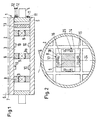
- Fig. 1 shows a longitudinal section through a calender roll 1 with a roll shell 2, the interior 3 surrounds.
- the calender roll 1 also has roll journals 4 on, which are connected to tenon washers 5, the Complete interior 3 on the front. The presence however, the roll neck 4 and the pin washers 5 not necessarily required.
- the calender roll 1 works with at least a counter-roller 6 shown in broken lines. Between the calender roll 1 and the counter roll 6 a nip 7 is formed through which a material web, for example a paper web, can be guided to with increased pressure and possibly also with increased Temperature can be applied. Possibly the counter roller 6 is heated.
- a material web for example a paper web
- roller jacket 2 on its outer peripheral surface Have plastic covering so that the calender roll 1 is designed as an elastic or "soft” roller.
- the actuators are variable in length in the embodiment of FIG. 1. They are with one end on the roll shell 2 attached. At the other end they are with an inertial mass 9 connected. So when an actuator 8 is actuated is then shortened or extended the distance between the inertial mass 9 and the roll shell 2. Since for the displacement of the inertial mass 9 a certain force is required a corresponding counter or reaction force on the Roller jacket 2 back.
- sensors 10 are also arranged determine the vibrations of the roll shell 2. With a 1 and 2 control device not shown in detail you can now control the actuators 8 that the vibrations determined by the sensors 10 are kept as small as possible or even disappear. If the roller shell 2 no longer vibrates, then the risk of barring is drastically reduced been.
- the vibrations provide that the frequency, with which the actuators are operated (here frequencies between 100 and 1000 Hz) in operation at intervals or continuously varies so that the resulting vibration of the roll shell 2 does not remain on one frequency long enough, to allow barring.
- the actuators can be electromagnets.
- the electromagnets are over two slip rings 11 with electric current below a predetermined Power supplied.
- the slip rings can be used here one end of the calender roll 1 may be arranged. They are fed via contacts 12. Inside 3 the roll shell 2 can also be a power amplifier 13, optionally with a control device, be arranged, which then ultimately the actuators 8 controlled in the desired manner.
- a rotating one can also be used Transformer can be provided in which the electrical Power is transmitted inductively.
- an electric generator or to arrange a pump for air or a hydraulic fluid, caused by the rotation of the calender roll 1 are driven.
- the actuators can be shown in the drawing plane, as shown let it work. If the actuators turn, if the actuators with the roller shell 2 connected, you can control them, for example, that they always shift the inertial masses 9 only perform if the direction of movement the mass of inertia lies in the press plane.
- the Actuator arrangement shown in which one double-acting actuators 8, 8a in the press plane if the actuators do not turn.
- the vibration of the roller shell becomes the simplest
- the actuators also generate tensile forces, for example magnetically on Roller shell.
- the roll shell 2 slides on the actuators 8, 8a and with not shown Actuators 8, 8a are relative to means a fixed point, for example one not closer shown stand held. A stand is but not absolutely necessary if others Means are provided.
- the actuators 8, 8a with the help of a gravity pendulum or an opposing one the rotating field rotating to the roller are "held".
- Fig. 2 shows a modified embodiment in which same parts are provided with the same reference numerals.
- a cage-like support structure 14 which is made up of four plates, the one form centrally arranged square 15 and in rest on the inner wall of the roll shell 2.
- the inertial mass 9 arranged, on which four actuators 8 are arranged, which are designed as electromagnets.
- Any electromagnet has an E-shaped yoke 16 around which middle coil a coil 17 is placed.
- the thigh of the yoke together with the cage arrangement 14 Air gaps 18.
- coil 17 When coil 17 is powered then the electromagnet pulls the inertial mass 9 closer to the corresponding side of the cage assembly 14 or he pushes them off accordingly. This too In this way, the roller shell 2 can impart an oscillation.
- the direction of the resulting force can be change. For example, if you follow the in Fig. 2 pointing upwards and the one pointing to the right in FIG. 2 Actuator actuated simultaneously and with the same intensity, then there is a force that is below one An angle of 45 ° acts on the roller jacket 2. If drives the actuators out of phase, then you can generate a force vector that is relative to the roll shell 2 rotates. In the present embodiment with four actuators evenly distributed in the circumferential direction 8, combined into an actuator group are such a rotating force generation, achieve, for example, that the individual Actuators loaded with sinusoidal alternating currents, which are electrically offset from each other by 90 ° are.
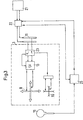
- FIG. 3 shows schematically in the form of a circuit diagram, how the actuators 8 are controlled.
- the actuators are shown here in the form of double arrows.
- the Interior 3 is delimited by a dashed line.
- the calender roll 1 has a tachometer generator 19 provided, which generates information about the speed. In a signal processor 20 one can, if necessary also information about the respective Win the angle of rotation of the roller.
- a power supply device 21 feeds through the Slip rings 11 the power amplifier 13, which in turn in turn controls the actuators 8.
- a modulation device is arranged, which in the present case as a multiplexer / demultiplexer is trained.
- the modulation device 22 shapes those coming from the processor 20 Signals on the transmitted to the slip rings 11 Power on.
- a corresponding demodulation device 23 is arranged in the interior 3.
- the demodulation device 23 is also a multiplexer / demultiplexer educated. It is also capable of the sensor assembly 10 originating signals via the multiplexer 22 to deliver to the processor 20.
- the processor 20 is thus able to control the actuators 8 to be controlled so that the vibrations of the roll shell 2 either be almost eliminated or the Vibrations of the roll shell 2 not long enough a frequency range around a barring allow.
Landscapes
- Engineering & Computer Science (AREA)
- General Engineering & Computer Science (AREA)
- Mechanical Engineering (AREA)
- Paper (AREA)
- Rolls And Other Rotary Bodies (AREA)
Abstract
Description
- Fig. 1
- einen Längsschnitt durch eine erste Ausführungsform einer Walze,
- Fig. 2
- einen Querschnitt durch eine abgewandelte Ausführungsform einer Walze und
- Fig. 3
- eine schematische Schaltungsanordnung zur Erläuterung des Betriebs der Walze.
Claims (19)
- Verfahren zum Betrieb einer Kalanderwalze mit einem Walzenmantel, der einen Innenraum umgibt, dadurch gekennzeichnet, daß man im Innenraum eine aktive Schwingung erzeugt, die auf den Walzenmantel wirkt.
- Verfahren nach Anspruch 1, dadurch gekennzeichnet, daß man eine resultierende Schwingung am Walzenmantel ermittelt und die aktive Schwingung in Abhängigkeit von der resultierenden Schwingung steuert.
- Verfahren nach Anspruch 1 oder 2, dadurch gekennzeichnet, daß man die Frequenz und/oder Phase der aktiven Schwingung im Betrieb verändert.
- Verfahren nach einem der Ansprüche 1 bis 3, dadurch gekennzeichnet, daß die aktive Schwingung im wesentlichen in Pressenrichtung der Walze gerichtet ist.
- Kalanderwalze mit einem Walzenmantel, der einen Innenraum umgibt, dadurch gekennzeichnet, daß in dem Innenraum (3) mindestens ein auf den Walzenmantel (2) wirkender Aktuator (8) angeordnet ist.
- Kalanderwalze nach Anspruch 5, dadurch gekennzeichnet, daß der Aktuator (8) zwischen einer Trägheitsmasse (9) und dem Walzenmantel (2) angeordnet ist.
- Kalanderwalze nach Anspruch 5 oder 6, dadurch gekennzeichnet, daß mehrere Aktuatoren (8) über die axiale Länge des Walzenmantels (2) verteilt sind.
- Kalanderwalze nach einem der Ansprüche 5 bis 7, dadurch gekennzeichnet, daß mindestens zwei Aktuatoren (8, 25), die senkrecht zur Walzenachse wirken und die im wesentlichen an der gleichen axialen Position angeordnet sind, zu einer Gruppe zusammengefaßt sind.
- Kalanderwalze nach Anspruch 8, dadurch gekennzeichnet, daß die Aktuatoren (8, 25) einer Gruppe rotationssymmetrisch um die Walzenachse herum angeordnet sind.
- Kalanderwalze nach einem der Ansprüche 5 bis 9, dadurch gekennzeichnet, daß im Walzenmantel (2) eine Sensoranordnung (10) angeordnet ist, die mit einer Steuereinrichtung (20) in Verbindung steht, die den mindestens einen Aktuator (8, 25) ansteuert.
- Kalanderwalze nach Anspruch 10, dadurch gekennzeichnet, daß die Steuereinrichtung (20) einen Drehzahl- und/oder einen Drehwinkeleingang aufweist.
- Kalanderwalze nach einem der Ansprüche 5 bis 11, dadurch gekennzeichnet, daß die Aktuatoren (8, 25) Elektromagnete aufweisen.
- Kalanderwalze nach einem der Ansprüche 5 bis 12, dadurch gekennzeichnet, daß der Aktuator (8) mit dem Walzenmantel mitdreht.
- Kalanderwalze nach einem der Ansprüche 5 bis 13, dadurch gekennzeichnet, daß eine elektrische Energieübertragungseinrichtung (11) an einem Ende des Walzenmantels (2) angeordnet ist.
- Kalanderwalze nach Anspruch 14, dadurch gekennzeichnet, daß die elektrische Energieübertragungseinrichtung eine Schleifringanordnung (11) aufweist.
- Kalanderwalze nach Anspruch 14, dadurch gekennzeichnet, daß die elektrische Energieübertragungseinrichtung eine induktive Kopplung aufweist.
- Kalanderwalze nach einem der Ansprüche 5 bis 13, dadurch gekennzeichnet, daß zwischen der Energieübertragungseinrichtung und einer Energieversorgungseinrichtung eine Modulationseinrichtung (22) angeordnet ist, die ein Signal in die übertragene elektrische Energie einspeist.
- Kalanderwalze nach einem der Ansprüche 5 bis 13, dadurch gekennzeichnet, daß ein Generator im Walzenmantel (2) vorgesehen ist, der durch Rotation der Walze angetrieben ist.
- Kalanderwalze nach einem der Ansprüche 5 bis 18, dadurch gekennzeichnet, daß der Walzenmantel (2) im Bereich eines jeden Aktuators (8, 25) eine Käfigstruktur (14) aufweist.
Applications Claiming Priority (2)
| Application Number | Priority Date | Filing Date | Title |
|---|---|---|---|
| DE10008800A DE10008800B4 (de) | 2000-02-25 | 2000-02-25 | Verfahren zum Betrieb einer Kalanderwalze und Kalanderwalze |
| DE10008800 | 2000-02-25 |
Publications (3)
| Publication Number | Publication Date |
|---|---|
| EP1127977A2 true EP1127977A2 (de) | 2001-08-29 |
| EP1127977A3 EP1127977A3 (de) | 2002-07-24 |
| EP1127977B1 EP1127977B1 (de) | 2008-03-26 |
Family
ID=7632327
Family Applications (1)
| Application Number | Title | Priority Date | Filing Date |
|---|---|---|---|
| EP01103141A Expired - Lifetime EP1127977B1 (de) | 2000-02-25 | 2001-02-10 | Verfahren zum Betrieb einer Kalanderwalze und Kalanderwalze |
Country Status (3)
| Country | Link |
|---|---|
| US (1) | US6464834B2 (de) |
| EP (1) | EP1127977B1 (de) |
| DE (2) | DE10008800B4 (de) |
Cited By (5)
| Publication number | Priority date | Publication date | Assignee | Title |
|---|---|---|---|---|
| EP1275774A1 (de) * | 2001-07-12 | 2003-01-15 | Voith Paper Patent GmbH | Verfahren zum Betreiben eines Kalanders und Kalander |
| US6851356B2 (en) | 2001-07-12 | 2005-02-08 | Voith Paper Patent Gmbh | Calender and process for arranging rolls in a roll stack of a calender |
| US6892631B2 (en) | 2001-07-12 | 2005-05-17 | Voith Paper Patent Gmbh | Process for operating a calender |
| US6902691B2 (en) | 2001-07-12 | 2005-06-07 | Voith Paper Patent Gmbh | Process for operating a calendar |
| AT506011B1 (de) * | 2007-09-28 | 2012-01-15 | Metso Paper Inc | Verfahren zur dämpfung periodisch auftretender schwingungen in einer faserbahnmaschine |
Families Citing this family (15)
| Publication number | Priority date | Publication date | Assignee | Title |
|---|---|---|---|---|
| DE10213851A1 (de) | 2002-03-27 | 2003-10-09 | Voith Paper Patent Gmbh | Verfahren zum Betreiben einer Papiermaschine sowie Papiermaschine |
| DE10221680C1 (de) * | 2002-05-16 | 2003-10-09 | Voith Paper Patent Gmbh | Kalander und Verfahren zum Betreiben eines Kalanders |
| DE10248519B4 (de) * | 2002-10-17 | 2006-11-02 | Voith Patent Gmbh | Mittelwalze eines Kalanders und Kalander |
| DE102005026907A1 (de) * | 2005-06-10 | 2006-12-14 | Voith Patent Gmbh | Biegeausgleichwalze |
| US20080000363A1 (en) * | 2006-06-29 | 2008-01-03 | Metso Paper, Inc. | Adjustable Anti-Barring Device for Calender Rolls |
| FI119334B (fi) * | 2007-09-06 | 2008-10-15 | Metso Paper Inc | Menetelmä ja järjestely värähtelyjen estämiseksi paperi-/kartonkikoneen telaryhmässä |
| DE102008026344A1 (de) | 2008-05-31 | 2009-12-03 | Voith Patent Gmbh | Verfahren zum Betreiben eines Kalanders und Kalander |
| JP2010275673A (ja) * | 2009-06-01 | 2010-12-09 | Seed:Kk | 古紙再生装置のベルト蛇行防止装置、抄紙装置および古紙再生装置 |
| WO2011086847A1 (en) * | 2010-01-15 | 2011-07-21 | Semiconductor Energy Laboratory Co., Ltd. | Semiconductor device |
| DE102010002129A1 (de) | 2010-02-18 | 2011-08-18 | Voith Patent GmbH, 89522 | Walze und Verfahren zur Vermeidung von Schwingungen |
| DE102010029492A1 (de) | 2010-05-31 | 2011-12-01 | Voith Patent Gmbh | Walze und Verfahren zur Vermeidung ihrer Schwingungen |
| DE102010039387A1 (de) | 2010-08-17 | 2012-02-23 | Voith Patent Gmbh | Verfahren zur Vermeidung von Barringerscheinungen |
| DE102010041615A1 (de) | 2010-09-29 | 2012-03-29 | Voith Patent Gmbh | Verfahren zum Betreiben eines Kalanders |
| DE102010061915A1 (de) | 2010-11-25 | 2012-05-31 | Voith Patent Gmbh | Walze und Verfahren zur Druckbehandlung einer Warenbahn |
| DE102012219062A1 (de) * | 2012-10-19 | 2014-04-24 | Robert Bosch Gmbh | Energieübertragungsvorrichtung und Energieübertragungsanordnung |
Citations (3)
| Publication number | Priority date | Publication date | Assignee | Title |
|---|---|---|---|---|
| US3266414A (en) * | 1962-05-30 | 1966-08-16 | Karlstads Mek Ab | Calenders to overcome barring |
| DE19652769A1 (de) * | 1996-12-18 | 1998-06-25 | Voith Sulzer Papiermasch Gmbh | Verfahren und Vorrichtung zur Dämpfung von Kontaktschwingungen |
| WO1999004181A2 (en) * | 1997-07-15 | 1999-01-28 | Lord Corporation | Vibration control apparatus and method for calender rolls and the like |
Family Cites Families (8)
| Publication number | Priority date | Publication date | Assignee | Title |
|---|---|---|---|---|
| US1000065A (en) | 1910-04-08 | 1911-08-08 | Lyman Paul Armstrong | System of heating and ventilating. |
| US3456582A (en) * | 1966-09-29 | 1969-07-22 | Beloit Corp | Crownless electromagnetic press roll loading |
| DE2851747C2 (de) * | 1978-11-30 | 1986-05-28 | Kleinewefers Gmbh, 4150 Krefeld | Druckbehandlungs- oder Transportwalze, insbesondere Kalanderwalze |
| SE432792B (sv) * | 1982-04-01 | 1984-04-16 | Dynapac Maskin Ab | Forfarande och anordning for att astadkomma optimal packningsgrad vid packning av olika material sasom asfalt, jord etc medelst en vibrerande velt |
| US4943224A (en) * | 1989-02-10 | 1990-07-24 | General Electric Company | Apparatus employing integral dielectric heater for roll forming thermoplastic material |
| US5821498A (en) * | 1990-08-15 | 1998-10-13 | Valmet Corporation | Method for heating of a roll and a heatable roll |
| US5768985A (en) * | 1995-12-11 | 1998-06-23 | Valmet Corporation | Method for preventing vibrations of a roll set |
| FI104207B (fi) * | 1998-07-24 | 1999-11-30 | Valmet Corp | Menetelmä ja laite paperi- tai kartonkikoneen nippitelarakenteen ominaistaajuuden muuttamiseksi |
-
2000
- 2000-02-25 DE DE10008800A patent/DE10008800B4/de not_active Withdrawn - After Issue
-
2001
- 2001-02-10 DE DE50113771T patent/DE50113771D1/de not_active Expired - Lifetime
- 2001-02-10 EP EP01103141A patent/EP1127977B1/de not_active Expired - Lifetime
- 2001-02-23 US US09/790,687 patent/US6464834B2/en not_active Expired - Fee Related
Patent Citations (3)
| Publication number | Priority date | Publication date | Assignee | Title |
|---|---|---|---|---|
| US3266414A (en) * | 1962-05-30 | 1966-08-16 | Karlstads Mek Ab | Calenders to overcome barring |
| DE19652769A1 (de) * | 1996-12-18 | 1998-06-25 | Voith Sulzer Papiermasch Gmbh | Verfahren und Vorrichtung zur Dämpfung von Kontaktschwingungen |
| WO1999004181A2 (en) * | 1997-07-15 | 1999-01-28 | Lord Corporation | Vibration control apparatus and method for calender rolls and the like |
Cited By (6)
| Publication number | Priority date | Publication date | Assignee | Title |
|---|---|---|---|---|
| EP1275774A1 (de) * | 2001-07-12 | 2003-01-15 | Voith Paper Patent GmbH | Verfahren zum Betreiben eines Kalanders und Kalander |
| US6851356B2 (en) | 2001-07-12 | 2005-02-08 | Voith Paper Patent Gmbh | Calender and process for arranging rolls in a roll stack of a calender |
| US6857356B2 (en) | 2001-07-12 | 2005-02-22 | Voith Paper Patent Gmbh | Calender and process for operating a calendar |
| US6892631B2 (en) | 2001-07-12 | 2005-05-17 | Voith Paper Patent Gmbh | Process for operating a calender |
| US6902691B2 (en) | 2001-07-12 | 2005-06-07 | Voith Paper Patent Gmbh | Process for operating a calendar |
| AT506011B1 (de) * | 2007-09-28 | 2012-01-15 | Metso Paper Inc | Verfahren zur dämpfung periodisch auftretender schwingungen in einer faserbahnmaschine |
Also Published As
| Publication number | Publication date |
|---|---|
| DE50113771D1 (de) | 2008-05-08 |
| DE10008800A1 (de) | 2001-09-20 |
| DE10008800B4 (de) | 2005-10-27 |
| EP1127977B1 (de) | 2008-03-26 |
| EP1127977A3 (de) | 2002-07-24 |
| US20020060021A1 (en) | 2002-05-23 |
| US6464834B2 (en) | 2002-10-15 |
Similar Documents
| Publication | Publication Date | Title |
|---|---|---|
| EP1127977A2 (de) | Verfahren zum Betrieb einer Kalanderwalze und Kalanderwalze | |
| DE2851747C2 (de) | Druckbehandlungs- oder Transportwalze, insbesondere Kalanderwalze | |
| EP0675224B1 (de) | Pressvorrichtung für bahnförmiges Material | |
| EP0854233A2 (de) | Verfahren und Vorrichtung zur Dämpfung von Kontaktschwingungen rotierender Walzen | |
| DE3216182C3 (de) | Kalander für Papier- und andere Materialbahnen | |
| DE10248519B4 (de) | Mittelwalze eines Kalanders und Kalander | |
| EP1483444A1 (de) | Verfahren und vorrichtung zur verminderung von schwingungen an rotierenden bauteilen | |
| EP0949378B1 (de) | Walzenmaschine und Verfahren zu ihrem Betrieb | |
| DE4015245A1 (de) | Durchbiegungseinstellwalze | |
| EP1835207A1 (de) | Wellendichtung | |
| EP0918947B1 (de) | Verfahren und vorrichtung zum verändern der durchbiegung einer welle, achse oder eines anderen trägers | |
| DE102007041931A1 (de) | Walzenanordnung | |
| EP0439684A1 (de) | Stanzpresse | |
| EP1371776B1 (de) | Kalander und Verfahren zum Betreiben eines Kalanders | |
| EP1790600B1 (de) | Rollenwickeleinrichtung | |
| EP1333123B1 (de) | Verfahren und Vorrichtung zur aktiven Dämpfung von Schwingungen in einer Vorrichtung zum Bearbeiten einer laufenden Bahn | |
| EP2337643B1 (de) | Verfahren und vorrichtung zur verbesserung mechanischer eigenschaften von magnetisch aktivierbaren materialien | |
| DE19819663B4 (de) | Walze mit Verminderung des Rundlauffehlers | |
| DE102007035476A1 (de) | Verfahren zum Betreiben einer Druckmaschine | |
| AT505571B1 (de) | Steuerventil | |
| EP1912768B1 (de) | Querschneider mit schwingungsdämpfung | |
| EP1275777B1 (de) | Verfahren zum Betreiben eines Kalanders | |
| EP1961992A2 (de) | Vorrichtung und Verfahren zur aktiven Schwingungsdämpfung bei gegenläufig rotierenden Walzen | |
| DE4042365C2 (de) | Durchbiegungseinstellwalze | |
| EP2577078A1 (de) | Walze und verfahren zur vermeidung ihrer schwingungen |
Legal Events
| Date | Code | Title | Description |
|---|---|---|---|
| PUAI | Public reference made under article 153(3) epc to a published international application that has entered the european phase |
Free format text: ORIGINAL CODE: 0009012 |
|
| AK | Designated contracting states |
Kind code of ref document: A2 Designated state(s): AT BE CH CY DE DK ES FI FR GB GR IE IT LI LU MC NL PT SE TR |
|
| AX | Request for extension of the european patent |
Free format text: AL;LT;LV;MK;RO;SI |
|
| PUAL | Search report despatched |
Free format text: ORIGINAL CODE: 0009013 |
|
| AK | Designated contracting states |
Kind code of ref document: A3 Designated state(s): AT BE CH CY DE DK ES FI FR GB GR IE IT LI LU MC NL PT SE TR |
|
| AX | Request for extension of the european patent |
Free format text: AL;LT;LV;MK;RO;SI |
|
| 17P | Request for examination filed |
Effective date: 20020702 |
|
| AKX | Designation fees paid |
Designated state(s): DE FI FR GB SE |
|
| 17Q | First examination report despatched |
Effective date: 20060731 |
|
| RAP1 | Party data changed (applicant data changed or rights of an application transferred) |
Owner name: VOITH PATENT GMBH |
|
| GRAP | Despatch of communication of intention to grant a patent |
Free format text: ORIGINAL CODE: EPIDOSNIGR1 |
|
| GRAS | Grant fee paid |
Free format text: ORIGINAL CODE: EPIDOSNIGR3 |
|
| GRAA | (expected) grant |
Free format text: ORIGINAL CODE: 0009210 |
|
| AK | Designated contracting states |
Kind code of ref document: B1 Designated state(s): DE FI FR GB SE |
|
| REG | Reference to a national code |
Ref country code: GB Ref legal event code: FG4D Free format text: NOT ENGLISH |
|
| REF | Corresponds to: |
Ref document number: 50113771 Country of ref document: DE Date of ref document: 20080508 Kind code of ref document: P |
|
| ET | Fr: translation filed | ||
| PLBE | No opposition filed within time limit |
Free format text: ORIGINAL CODE: 0009261 |
|
| STAA | Information on the status of an ep patent application or granted ep patent |
Free format text: STATUS: NO OPPOSITION FILED WITHIN TIME LIMIT |
|
| 26N | No opposition filed |
Effective date: 20081230 |
|
| PGFP | Annual fee paid to national office [announced via postgrant information from national office to epo] |
Ref country code: GB Payment date: 20090219 Year of fee payment: 9 |
|
| PGFP | Annual fee paid to national office [announced via postgrant information from national office to epo] |
Ref country code: FR Payment date: 20090220 Year of fee payment: 9 |
|
| GBPC | Gb: european patent ceased through non-payment of renewal fee |
Effective date: 20100210 |
|
| REG | Reference to a national code |
Ref country code: FR Ref legal event code: ST Effective date: 20101029 |
|
| PG25 | Lapsed in a contracting state [announced via postgrant information from national office to epo] |
Ref country code: FR Free format text: LAPSE BECAUSE OF NON-PAYMENT OF DUE FEES Effective date: 20100301 |
|
| PG25 | Lapsed in a contracting state [announced via postgrant information from national office to epo] |
Ref country code: GB Free format text: LAPSE BECAUSE OF NON-PAYMENT OF DUE FEES Effective date: 20100210 |
|
| PGFP | Annual fee paid to national office [announced via postgrant information from national office to epo] |
Ref country code: SE Payment date: 20130219 Year of fee payment: 13 |
|
| REG | Reference to a national code |
Ref country code: SE Ref legal event code: EUG |
|
| PG25 | Lapsed in a contracting state [announced via postgrant information from national office to epo] |
Ref country code: SE Free format text: LAPSE BECAUSE OF NON-PAYMENT OF DUE FEES Effective date: 20140211 |
|
| PGFP | Annual fee paid to national office [announced via postgrant information from national office to epo] |
Ref country code: DE Payment date: 20150219 Year of fee payment: 15 Ref country code: FI Payment date: 20150211 Year of fee payment: 15 |
|
| REG | Reference to a national code |
Ref country code: DE Ref legal event code: R119 Ref document number: 50113771 Country of ref document: DE |
|
| PG25 | Lapsed in a contracting state [announced via postgrant information from national office to epo] |
Ref country code: FI Free format text: LAPSE BECAUSE OF NON-PAYMENT OF DUE FEES Effective date: 20160210 |
|
| PG25 | Lapsed in a contracting state [announced via postgrant information from national office to epo] |
Ref country code: DE Free format text: LAPSE BECAUSE OF NON-PAYMENT OF DUE FEES Effective date: 20160901 |