EP1127740A1 - Projecteur de véhicule automobile à masque et réflecteur - Google Patents
Projecteur de véhicule automobile à masque et réflecteur Download PDFInfo
- Publication number
- EP1127740A1 EP1127740A1 EP01400053A EP01400053A EP1127740A1 EP 1127740 A1 EP1127740 A1 EP 1127740A1 EP 01400053 A EP01400053 A EP 01400053A EP 01400053 A EP01400053 A EP 01400053A EP 1127740 A1 EP1127740 A1 EP 1127740A1
- Authority
- EP
- European Patent Office
- Prior art keywords
- reflector
- mask
- projector
- projector according
- clipping
- Prior art date
- Legal status (The legal status is an assumption and is not a legal conclusion. Google has not performed a legal analysis and makes no representation as to the accuracy of the status listed.)
- Granted
Links
Images




Classifications
-
- B—PERFORMING OPERATIONS; TRANSPORTING
- B60—VEHICLES IN GENERAL
- B60Q—ARRANGEMENT OF SIGNALLING OR LIGHTING DEVICES, THE MOUNTING OR SUPPORTING THEREOF OR CIRCUITS THEREFOR, FOR VEHICLES IN GENERAL
- B60Q1/00—Arrangement of optical signalling or lighting devices, the mounting or supporting thereof or circuits therefor
- B60Q1/0029—Spatial arrangement
- B60Q1/0041—Spatial arrangement of several lamps in relation to each other
-
- B—PERFORMING OPERATIONS; TRANSPORTING
- B60—VEHICLES IN GENERAL
- B60Q—ARRANGEMENT OF SIGNALLING OR LIGHTING DEVICES, THE MOUNTING OR SUPPORTING THEREOF OR CIRCUITS THEREFOR, FOR VEHICLES IN GENERAL
- B60Q1/00—Arrangement of optical signalling or lighting devices, the mounting or supporting thereof or circuits therefor
- B60Q1/02—Arrangement of optical signalling or lighting devices, the mounting or supporting thereof or circuits therefor the devices being primarily intended to illuminate the way ahead or to illuminate other areas of way or environments
- B60Q1/04—Arrangement of optical signalling or lighting devices, the mounting or supporting thereof or circuits therefor the devices being primarily intended to illuminate the way ahead or to illuminate other areas of way or environments the devices being headlights
- B60Q1/06—Arrangement of optical signalling or lighting devices, the mounting or supporting thereof or circuits therefor the devices being primarily intended to illuminate the way ahead or to illuminate other areas of way or environments the devices being headlights adjustable, e.g. remotely-controlled from inside vehicle
- B60Q1/068—Arrangement of optical signalling or lighting devices, the mounting or supporting thereof or circuits therefor the devices being primarily intended to illuminate the way ahead or to illuminate other areas of way or environments the devices being headlights adjustable, e.g. remotely-controlled from inside vehicle by mechanical means
- B60Q1/0683—Adjustable by rotation of a screw
-
- F—MECHANICAL ENGINEERING; LIGHTING; HEATING; WEAPONS; BLASTING
- F21—LIGHTING
- F21S—NON-PORTABLE LIGHTING DEVICES; SYSTEMS THEREOF; VEHICLE LIGHTING DEVICES SPECIALLY ADAPTED FOR VEHICLE EXTERIORS
- F21S41/00—Illuminating devices specially adapted for vehicle exteriors, e.g. headlamps
- F21S41/50—Illuminating devices specially adapted for vehicle exteriors, e.g. headlamps characterised by aesthetic components not otherwise provided for, e.g. decorative trim, partition walls or covers
- F21S41/55—Attachment thereof
-
- F—MECHANICAL ENGINEERING; LIGHTING; HEATING; WEAPONS; BLASTING
- F21—LIGHTING
- F21S—NON-PORTABLE LIGHTING DEVICES; SYSTEMS THEREOF; VEHICLE LIGHTING DEVICES SPECIALLY ADAPTED FOR VEHICLE EXTERIORS
- F21S43/00—Signalling devices specially adapted for vehicle exteriors, e.g. brake lamps, direction indicator lights or reversing lights
- F21S43/50—Signalling devices specially adapted for vehicle exteriors, e.g. brake lamps, direction indicator lights or reversing lights characterised by aesthetic components not otherwise provided for, e.g. decorative trim, partition walls or covers
-
- B—PERFORMING OPERATIONS; TRANSPORTING
- B60—VEHICLES IN GENERAL
- B60Q—ARRANGEMENT OF SIGNALLING OR LIGHTING DEVICES, THE MOUNTING OR SUPPORTING THEREOF OR CIRCUITS THEREFOR, FOR VEHICLES IN GENERAL
- B60Q2200/00—Special features or arrangements of vehicle headlamps
- B60Q2200/30—Special arrangements for adjusting headlamps, e.g. means for transmitting the movements for adjusting the lamps
- B60Q2200/36—Conjoint adjustments, i.e. a mechanical link allows conjoint adjustment of several units
Definitions
- the invention relates to vehicle headlights automobile.
- a motor vehicle headlamp comprising a housing, a reflector and a mask visible from outside the projector between the reflector and housing.
- the projector has a plate carrying the reflector, the mask and the lamp holder.
- the orientation of the projector beam by report to the vehicle can be adjusted by a means connecting the plate to the housing. It can be a manual adjustment means (local or from the control panel edge) and occasional, or a means of correction automatic, for example depending on the base of the vehicle.
- the assembly of these different pieces between them is relatively long.
- An object of the invention is to provide a projector faster to assemble.
- a vehicle headlamp comprising at least one reflector, a housing and a mask visible between the reflector and the housing from the exterior of the projector, in which the reflector and the mask include direct clipping means, one to the other.
- the clipping makes it possible to fix the mask to the reflector quickly, reliably and inexpensively. We therefore makes manufacturing faster.
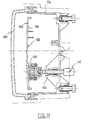
- the projector 2 has a case 4 and a lens 6 fixed to the latter in defining an internal enclosure to the projector.
- the projector has a reflector 8 comprising a wall 10 with reflecting face 12 in the form of paraboloid.
- the reflector has a rear base 14 comprising a flat wall 16 in the general shape of disc coaxial with axis 18 of the reflecting wall and a cylindrical border 19 of axis 18 extending towards the rear from the flat wall 16.
- the wall reflective 10 and the flat wall 16 are joined in their central area, these having an opening 20 along axis 18.
- the reflector 8 is of a single room.
- the projector has a lamp holder 22 fixed to the reflector by appropriate means and supporting a lamp 24 extending into opening 20.
- the projector has a mask 26 extending circumferentially between the reflecting wall 10 and the housing 4.
- the mask 26 has at the front a annular edge 28 extending radially at direction from the outside towards the housing the wall reflective of the reflector. This border is locally inclined towards the front and the axis 18. It is visible from outside the projector between the reflector and housing. It aims to hide a large part of the housing for an observer placed in front of the mirror.
- the mask has a skirt 30 extending backwards from edge 28.
- the skirt includes a first cylindrical section 32 of axis 18 followed by a second frustoconical section 34 of axis 18 narrowing towards the rear.
- the skirt 30 has a rear edge carrying a series of lugs 35 and a series of stops 36.
- the lugs 35 include cylinder sections of axis 18 returning axially towards the front from the back edge of the skirt.
- the front end of each lug 35 extends projecting radial towards axis 18.
- the stops 36 have annular wall sections plane perpendicular to the axis 18.
- the pins 35 are here 4 in number, just like the stops 36 with which they are regularly alternated around axis 18. The pins are capable of coming to bear along axis 18 on wall 16 to urge it backwards, while the stops 36 are suitable for come to rest along axis 18 on the rear edge free of the cylindrical edge 19 to request it forward.
- the second section frustoconical 34 of the skirt has notches 37 between lugs 35 and stops 36 to increase the elasticity of the pins.
- the projector has in addition a position corrector 40 known per se, of which only the actuating rod 42 has been shown. It is movable by sliding through a bearing of the housing 4, essentially following a direction parallel to axis 18.
- This rod is connected by a ball joint connection directly to part of the mask 26.
- This connection is for example obtained by blistering a spherical face of the rod 42 in a housing adapted from the mask.
- the assembly formed by the reflector 8, the mask 26, the lamp holder 22 and the lamp 24 is by elsewhere supported in a mobile way in one or two others fixed points of the case so that the sliding of the rod 42 modifies the inclination of this assembly by relation to the housing in one or two planes perpendicular to each other.
- the mask therefore fills a adjustment stage function.
- the projector has a single main lamp 24, i.e. a single lamp providing a lighting function.
- the projector is a double projector and has two subsets with main lamp 124, lamp holder 122, reflector 108 and mask 126.
- Each of these sub-assemblies is broadly similar to that of the first mode so that their description will not be repeated.
- the glass 106 and the housing 104 define an enclosure common to the two subsets.
- the two reflectors 108 are independent of each other.
- the two masks 126 are in one piece one with the other.
- Each of the two reflectors 108 is therefore fixed to mask 126 by clipping into the housing corresponding, as shown in particular in the figures 9 and 10. This time, the pins 135 are still at number of three for each reflector. But every time lug 135 are associated in their own two stops 136 extending on either side of the lug. The stops are therefore six in number for each reflector.
- slats are provided for each reflector radial positioning 141, here six in number, and regularly distributed around axis 118 of the accommodation reflector. Each strip extends substantially parallel to axis 118 and comes to stress the wall 119 for the radial centering of the reflector on the axis 118.
- the lower subset of Figure 8 comprises, in addition to the main lamp 124, a city lamp 150 extending offset in a lateral orifice of the reflecting wall 112. The face reflective of the upper light in figure 8 shows streaks.
- the corrector position 140 can extend to one end of the case so that one of the subsets is interposed between the corrector 140 and the other sub-assembly.
- the corrector extends laterally opposite the wall reflective, on the side opposite the reflective face 112.
- the rod 140 is engaged with a rear relief 133 of a plate 129 extending in the plane of the borders 128 and extending them in one piece with the masks.
- the two subsets connected to the piece forming the two masks 126 form therewith a self-contained group. This group is operated by compared to the housing 104 for its good orientation thanks corrector 140.
- the part forming the masks 126 therefore form the adjustment plate.
- the corrector 140 is connected to the part forming the masks between the two reflectors 108.
- each of the reflectors 108 is clipped into its mask 126 in the same way as for the first mode. Clipping fastening ensures good hold relative of the two vibrating parts.
- each reflector is planned to be fixed in addition 108 to the mask 126 by screws.
- ears 150 illustrated in Figures 13 and 15, extending radially in the direction axis 118 from the rear edge of wall 119. The ears receive screws screwed into a wall of the base 114 perpendicular to the axis 118.
- the stops 36 and 136 are configured to present a certain axial elasticity to make up for the axial play of the mask relative to the reflector.
- the mask can be made of material plastic by molding using a form mold simple. In particular, it does not have to be mold has drawers.
- the corrector 40, 140 may be manual or automatic. It will be able to act on the position in site and / or in azimuth.
Landscapes
- Engineering & Computer Science (AREA)
- General Engineering & Computer Science (AREA)
- Mechanical Engineering (AREA)
- Non-Portable Lighting Devices Or Systems Thereof (AREA)
- Optical Radar Systems And Details Thereof (AREA)
Abstract
Description
- les moyens de clipsage étant aptes à former une butée à l'égard du déplacement du réflecteur par rapport au masque suivant une direction donnée dans un premier sens, le réflecteur et le masque comportent des moyens de butée interdisant le déplacement du réflecteur par rapport au masque dans cette direction et dans un deuxième sens ;
- les moyens de clipsage et les moyens de butée sont alternés circonférentiellement autour d'un axe du projecteur ;
- les moyens de clipsage comprennent des ergots portés par le masque ;
- le réflecteur comportant une paroi réfléchissante, les moyens de clipsage sont agencés de sorte que le réflecteur et le masque viennent en prise mutuelle à distance de cette paroi, à l'arrière de celle-ci ;
- le réflecteur comporte une embase s'étendant en partie arrière d'une paroi réfléchissante du réflecteur et au moyen de laquelle le réflecteur est fixé au masque ;
- le masque présente une partie évasée vers l'avant du projecteur et dans laquelle s'étend le réflecteur ;
- le masque et le réflecteur sont configurés pour assurer un centrage mutuel lors de l'approche de la position de clipsage ;
- le projecteur comporte des lamelles élastiques de centrage relatif du réflecteur et du masque.
- le réflecteur étant un premier réflecteur et le masque étant un premier masque, le projecteur comporte un deuxième réflecteur et un deuxième masque associé au deuxième réflecteur, les deux masques étant d'une seule pièce ;
- le projecteur comporte des moyens de clipsage direct du deuxième masque au deuxième réflecteur ;
- le projecteur comporte des moyens de réglage de la position du ou de chaque réflecteur par rapport au boítier ; et
- les moyens de réglage sont reliés directement au masque en vue du réglage.
- la figure 1 est une vue en section axiale verticale d'un projecteur selon un premier mode préféré de réalisation ;
- la figure 2 est une vue de face de certaines pièces du projecteur de la figure 1 ;
- les figures 3 et 4 sont deux vues en section axiale d'une partie du projecteur de la figure 1 suivant les plans III-III et IV-IV de la figure 2 ;
- les figures 5 à 7 sont trois vues en section axiale du projecteur de la figure 1, montrant trois étapes du clipsage du masque au réflecteur ;
- la figure 8 est une vue en section axiale horizontale d'un projecteur selon un deuxième mode de réalisation ;
- les figures 9, 10 et 11 sont des vues en section verticale selon les plans IX-IX, X-X et XI-XI du projecteur de la figure 8 ;
- la figure 12 est une vue partielle de face du projecteur de la figure 8, au niveau de la partie gauche de celui-ci ;
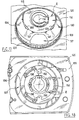
- les figures 13, 14 et 15 sont des vues partielles respectives en perspective et arrière du masque de la figure 8 seul ; et
- les figures 16, 17 et 18 sont des vues analogues aux figures 13, 14 et 15 du masque recevant le réflecteur, la face réfléchissante du réflecteur ayant été omise pour bien montrer les moyens de fixation.
Claims (13)
- Projecteur pour véhicule, comportant au moins un réflecteur (8 ; 108), un boítier (4 ; 104) et un masque (26 ; 126) visible entre le réflecteur et le boítier depuis l'extérieur du projecteur, caractérisé en ce que le réflecteur et le masque comportent des moyens (19, 35 ; 119, 135) de clipsage direct l'un à l'autre.
- Projecteur selon la revendication 1, caractérisé en ce que les moyens de clipsage étant aptes à former une butée à l'égard du déplacement du réflecteur (8 ; 108) par rapport au masque (26 ; 126) suivant une direction donnée (18 ; 118) dans un premier sens, le réflecteur et le masque comportent des moyens de butée (19, 36 ; 119, 136) interdisant le déplacement du réflecteur par rapport au masque dans cette direction (18 ; 118) et dans un deuxième sens.
- Projecteur selon la revendication 2, caractérisé en ce que les moyens de clipsage (35 ; 135) et les moyens de butée (36 ; 136) sont alternés circonférentiellement autour d'un axe (18 ; 118) du projecteur.
- Projecteur selon l'une quelconque des revendications 1 à 3, caractérisé en ce que les moyens de clipsage comprennent des ergots (35 ; 135) portés par le masque (26 ; 126).
- Projecteur selon l'une quelconque des revendications 1 à 4, caractérisé en ce que, le réflecteur (8 ; 108) comportant une paroi réfléchissante (10 ; 110), les moyens de clipsage sont agencés de sorte que le réflecteur et le masque viennent en prise mutuelle à distance de cette paroi, à l'arrière de celle-ci.
- Projecteur selon l'une quelconque des revendications 1 à 5, caractérisé en ce que le réflecteur (8 ; 108) comporte une embase (14 ; 114) s'étendant en partie arrière d'une paroi réfléchissante (10 ; 110) du réflecteur et au moyen de laquelle le réflecteur est fixé au masque.
- Projecteur selon l'une quelconque des revendications 1 à 6, caractérisé en ce que le masque (26 ; 126) présente une partie évasée (30 ; 130) vers l'avant du projecteur et dans laquelle s'étend le réflecteur.
- Projecteur selon l'une quelconque des revendications 1 à 7, caractérisé en ce que le masque (26 ; 126) et le réflecteur (8 ; 108) sont configurés pour assurer un centrage mutuel lors de l'approche de la position de clipsage.
- Projecteur selon l'une quelconque des revendications 1 à 8, caractérisé en ce qu'il comporte des lamelles élastiques (141) de centrage relatif du réflecteur et du masque.
- Projecteur selon l'une quelconque des revendications 1 à 9, caractérisé en ce que le réflecteur (108) étant un premier réflecteur et le masque (126) étant un premier masque, le projecteur comporte un deuxième réflecteur (108) et un deuxième masque (126) associé au deuxième réflecteur, les deux masques (126) étant d'une seule pièce.
- Projecteur selon la revendication 10, caractérisé en ce qu'il comporte des moyens de clipsage direct du deuxième masque au deuxième réflecteur.
- Projecteur selon l'une quelconque des revendications 1 à 11, caractérisé en ce qu'il comporte des moyens de réglage (40 ; 140) de la position du ou de chaque réflecteur (8 ; 108) par rapport au boítier (4 ; 104).
- Projecteur selon la revendication 12, caractérisé en ce que les moyens de réglage sont reliés directement au masque (26 ; 126) en vue du réglage.
Applications Claiming Priority (2)
| Application Number | Priority Date | Filing Date | Title |
|---|---|---|---|
| FR0002322A FR2805596B1 (fr) | 2000-02-24 | 2000-02-24 | Projecteur de vehicule automobile a masque et reflecteur |
| FR0002322 | 2000-02-24 |
Publications (2)
| Publication Number | Publication Date |
|---|---|
| EP1127740A1 true EP1127740A1 (fr) | 2001-08-29 |
| EP1127740B1 EP1127740B1 (fr) | 2011-02-02 |
Family
ID=8847353
Family Applications (1)
| Application Number | Title | Priority Date | Filing Date |
|---|---|---|---|
| EP01400053A Expired - Lifetime EP1127740B1 (fr) | 2000-02-24 | 2001-01-10 | Projecteur de véhicule automobile à masque et réflecteur |
Country Status (4)
| Country | Link |
|---|---|
| EP (1) | EP1127740B1 (fr) |
| AT (1) | ATE497455T1 (fr) |
| DE (1) | DE60143979D1 (fr) |
| FR (1) | FR2805596B1 (fr) |
Cited By (3)
| Publication number | Priority date | Publication date | Assignee | Title |
|---|---|---|---|---|
| DE10243575A1 (de) * | 2002-09-19 | 2004-04-01 | Volkswagen Ag | Befestigungsvorrichtung und Befestigungssystem für die Befestigung eines Anbauteils an einem Karosserieteil eines Fahrzeugs |
| FR2935115A1 (fr) * | 2008-08-21 | 2010-02-26 | Peugeot Citroen Automobiles Sa | Masque de bloc optique de vehicule automobile a insert(s) interchangeable(s) |
| FR3092535A1 (fr) * | 2019-02-11 | 2020-08-14 | Psa Automobiles Sa | Boîtier pour dispositif d’éclairage et de signalisation de véhicules automobiles |
Families Citing this family (1)
| Publication number | Priority date | Publication date | Assignee | Title |
|---|---|---|---|---|
| FR3140033A1 (fr) | 2022-09-22 | 2024-03-29 | Psa Automobiles Sa | Système d’assemblage d’un masque de projecteur pour véhicule automobile sur un réflecteur en matériau thermodurcissable |
Citations (2)
| Publication number | Priority date | Publication date | Assignee | Title |
|---|---|---|---|---|
| EP0054444A1 (fr) * | 1980-11-12 | 1982-06-23 | Regie Nationale Des Usines Renault | Projecteur pour véhicule automobile |
| DE19546271A1 (de) * | 1995-12-12 | 1997-06-19 | Bosch Gmbh Robert | Scheinwerfer für Fahrzeuge |
-
2000
- 2000-02-24 FR FR0002322A patent/FR2805596B1/fr not_active Expired - Fee Related
-
2001
- 2001-01-10 DE DE60143979T patent/DE60143979D1/de not_active Expired - Lifetime
- 2001-01-10 EP EP01400053A patent/EP1127740B1/fr not_active Expired - Lifetime
- 2001-01-10 AT AT01400053T patent/ATE497455T1/de not_active IP Right Cessation
Patent Citations (2)
| Publication number | Priority date | Publication date | Assignee | Title |
|---|---|---|---|---|
| EP0054444A1 (fr) * | 1980-11-12 | 1982-06-23 | Regie Nationale Des Usines Renault | Projecteur pour véhicule automobile |
| DE19546271A1 (de) * | 1995-12-12 | 1997-06-19 | Bosch Gmbh Robert | Scheinwerfer für Fahrzeuge |
Cited By (4)
| Publication number | Priority date | Publication date | Assignee | Title |
|---|---|---|---|---|
| DE10243575A1 (de) * | 2002-09-19 | 2004-04-01 | Volkswagen Ag | Befestigungsvorrichtung und Befestigungssystem für die Befestigung eines Anbauteils an einem Karosserieteil eines Fahrzeugs |
| FR2935115A1 (fr) * | 2008-08-21 | 2010-02-26 | Peugeot Citroen Automobiles Sa | Masque de bloc optique de vehicule automobile a insert(s) interchangeable(s) |
| FR3092535A1 (fr) * | 2019-02-11 | 2020-08-14 | Psa Automobiles Sa | Boîtier pour dispositif d’éclairage et de signalisation de véhicules automobiles |
| WO2020165515A1 (fr) * | 2019-02-11 | 2020-08-20 | Psa Automobiles Sa | Boîtier pour dispositif d'éclairage et de signalisation de véhicules automobiles |
Also Published As
| Publication number | Publication date |
|---|---|
| EP1127740B1 (fr) | 2011-02-02 |
| FR2805596A1 (fr) | 2001-08-31 |
| FR2805596B1 (fr) | 2002-04-12 |
| ATE497455T1 (de) | 2011-02-15 |
| DE60143979D1 (de) | 2011-03-17 |
Similar Documents
| Publication | Publication Date | Title |
|---|---|---|
| EP1644219B1 (fr) | Bloc projecteur pour vehicule automobile, et vehicule corresppondant | |
| FR2820706A1 (fr) | Ensemble de bloc avant de vehicule automobile comportant un dispositif ameliore de fixation des composants, et vehicule equipe d'un tel ensemble | |
| FR2818209A1 (fr) | Phare de vehicule a ampoule a decharge et circuit a ballast | |
| WO2002095286A1 (fr) | Ensemble de montage d'un spot auto-portant sur un plafond tendu | |
| EP2598795A1 (fr) | Dispositif de fixation d'un premier élément sur un second élément, par coopération entre des pattes d'immobilisation et des pattes de fixation | |
| EP1127740B1 (fr) | Projecteur de véhicule automobile à masque et réflecteur | |
| FR2808316A1 (fr) | Dispositif d'eclairage ou de signalisation pour vehicule a boitier renforce | |
| EP1127741B1 (fr) | Projecteur de véhicule automobile à masque et correcteur | |
| FR2808319A1 (fr) | Dispositif d'eclairage ou de signalisation pour vehicule de haute tenue thermique | |
| FR2624584A1 (fr) | Bloc optique pour vehicules automobiles avec fixation reglable | |
| EP0648642B1 (fr) | Feu de signalisation à optique réglable notamment pour lunette arrière de véhicule automobile | |
| EP1867918B1 (fr) | Projecteur comportant un élément de support rapporté fixe sur lequel un réflecteur est monté pivotant | |
| EP1160128B1 (fr) | Dispositif d'éclairage ou de signalisation pour véhicule comportant deux pièces fixées par clipsage | |
| EP0995947B1 (fr) | Feu de signalisation à porte-lampe integré au socle | |
| EP2952804B1 (fr) | Module lumineux pour véhicule et procédé de fixation | |
| EP1739345B1 (fr) | Module optique pour véhicule automobile | |
| FR2808318A1 (fr) | Dispositif d'eclairage ou de signalisation pour vehicule a ecran thermique | |
| EP3966496B1 (fr) | Module de signalisation de jour pour véhicules automobiles et ensemble d'éclairage et de signalisation comprenant ledit module | |
| FR2707730A1 (fr) | Projecteur pour véhicule avec support d'ampoule réglable. | |
| EP0698762B1 (fr) | Dispositif de montage d'un porte-lampe pour lampe de ville dans une partie inclinée d'un miroir de dispositif d'éclairage ou de signalisation de véhicule automobile | |
| EP1475268A1 (fr) | Agencement pour le positionnement et la fixation d'un élément d'équipement sur un véhicule automobile | |
| FR2735850A1 (fr) | Dispositif de montage d'un porte-lampe, notamment pour lampe de ville, dans une partie inclinee d'un miroir de dispositif d'eclairage ou de signalisation de vehicule automobile | |
| FR2746900A1 (fr) | Projecteur a barreau optique pour vehicule automobile | |
| FR3100596A1 (fr) | Dispositif de fixation réglable avec rattrapage de jeu des projecteurs de véhicules automobiles | |
| EP1129898A1 (fr) | Projecteur de véhicule automobile muni de moyens perfectionnés de montage d'un correcteur d'orientation de faisceau |
Legal Events
| Date | Code | Title | Description |
|---|---|---|---|
| PUAI | Public reference made under article 153(3) epc to a published international application that has entered the european phase |
Free format text: ORIGINAL CODE: 0009012 |
|
| AK | Designated contracting states |
Kind code of ref document: A1 Designated state(s): AT BE CH CY DE DK ES FI FR GB GR IE IT LI LU MC NL PT SE TR |
|
| AX | Request for extension of the european patent |
Free format text: AL;LT;LV;MK;RO;SI |
|
| AKX | Designation fees paid |
Free format text: AT DE ES IT |
|
| 17P | Request for examination filed |
Effective date: 20020521 |
|
| 17Q | First examination report despatched |
Effective date: 20090727 |
|
| GRAP | Despatch of communication of intention to grant a patent |
Free format text: ORIGINAL CODE: EPIDOSNIGR1 |
|
| GRAS | Grant fee paid |
Free format text: ORIGINAL CODE: EPIDOSNIGR3 |
|
| GRAA | (expected) grant |
Free format text: ORIGINAL CODE: 0009210 |
|
| AK | Designated contracting states |
Kind code of ref document: B1 Designated state(s): AT DE ES IT |
|
| REF | Corresponds to: |
Ref document number: 60143979 Country of ref document: DE Date of ref document: 20110317 Kind code of ref document: P |
|
| REG | Reference to a national code |
Ref country code: DE Ref legal event code: R096 Ref document number: 60143979 Country of ref document: DE Effective date: 20110317 |
|
| PG25 | Lapsed in a contracting state [announced via postgrant information from national office to epo] |
Ref country code: ES Free format text: LAPSE BECAUSE OF FAILURE TO SUBMIT A TRANSLATION OF THE DESCRIPTION OR TO PAY THE FEE WITHIN THE PRESCRIBED TIME-LIMIT Effective date: 20110513 |
|
| PG25 | Lapsed in a contracting state [announced via postgrant information from national office to epo] |
Ref country code: AT Free format text: LAPSE BECAUSE OF FAILURE TO SUBMIT A TRANSLATION OF THE DESCRIPTION OR TO PAY THE FEE WITHIN THE PRESCRIBED TIME-LIMIT Effective date: 20110202 |
|
| PLBE | No opposition filed within time limit |
Free format text: ORIGINAL CODE: 0009261 |
|
| STAA | Information on the status of an ep patent application or granted ep patent |
Free format text: STATUS: NO OPPOSITION FILED WITHIN TIME LIMIT |
|
| 26N | No opposition filed |
Effective date: 20111103 |
|
| REG | Reference to a national code |
Ref country code: DE Ref legal event code: R097 Ref document number: 60143979 Country of ref document: DE Effective date: 20111103 |
|
| PGFP | Annual fee paid to national office [announced via postgrant information from national office to epo] |
Ref country code: IT Payment date: 20120126 Year of fee payment: 12 |
|
| PGFP | Annual fee paid to national office [announced via postgrant information from national office to epo] |
Ref country code: DE Payment date: 20130110 Year of fee payment: 13 |
|
| REG | Reference to a national code |
Ref country code: DE Ref legal event code: R119 Ref document number: 60143979 Country of ref document: DE |
|
| REG | Reference to a national code |
Ref country code: DE Ref legal event code: R119 Ref document number: 60143979 Country of ref document: DE Effective date: 20140801 |
|
| PG25 | Lapsed in a contracting state [announced via postgrant information from national office to epo] |
Ref country code: DE Free format text: LAPSE BECAUSE OF NON-PAYMENT OF DUE FEES Effective date: 20140801 |
|
| PG25 | Lapsed in a contracting state [announced via postgrant information from national office to epo] |
Ref country code: IT Free format text: LAPSE BECAUSE OF NON-PAYMENT OF DUE FEES Effective date: 20140110 |