EP1127704B1 - Tintenflaschenmontiervorrichtung - Google Patents
Tintenflaschenmontiervorrichtung Download PDFInfo
- Publication number
- EP1127704B1 EP1127704B1 EP01102845A EP01102845A EP1127704B1 EP 1127704 B1 EP1127704 B1 EP 1127704B1 EP 01102845 A EP01102845 A EP 01102845A EP 01102845 A EP01102845 A EP 01102845A EP 1127704 B1 EP1127704 B1 EP 1127704B1
- Authority
- EP
- European Patent Office
- Prior art keywords
- bottle
- ink bottle
- ink
- projection
- chamber
- Prior art date
- Legal status (The legal status is an assumption and is not a legal conclusion. Google has not performed a legal analysis and makes no representation as to the accuracy of the status listed.)
- Expired - Lifetime
Links
Images



Classifications
-
- B—PERFORMING OPERATIONS; TRANSPORTING
- B41—PRINTING; LINING MACHINES; TYPEWRITERS; STAMPS
- B41L—APPARATUS OR DEVICES FOR MANIFOLDING, DUPLICATING OR PRINTING FOR OFFICE OR OTHER COMMERCIAL PURPOSES; ADDRESSING MACHINES OR LIKE SERIES-PRINTING MACHINES
- B41L13/00—Stencilling apparatus for office or other commercial use
- B41L13/18—Inking units
Definitions
- the present invention relates to an ink bottle set-up device, and more particularly, to an ink bottle set-up device for setting up an ink bottle having a positioning projection in a given position.
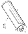
- an ink bottle 100 is made of plastic and comprises a cylindrical bottle body 101 internally filled with an ink, with a bottom wall having an ink discharging section 102 formed at a central position of the bottom wall.
- An outer periphery of the bottle body 101 is formed with three positioning ribs (positioning projections) 103 which extend along the length of the ink body 101, i.e., along an inserting direction of the ink bottle 100.
- the bottom wall of the bottle body 101 is also formed with an information indicating rib 104.
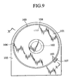
- FIG.9 is a front view of the ink bottle set-up device wherein the ink bottle 100 is located in a set-up position
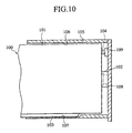
- FIG. 10 is a cross sectional view taken along line X-X of FIG. 9.
- a bottle set-up body 105 is formed with a bottle set-up chamber 106, and a rib-guide recess 107 opening to the bottle set-up chamber 106 and extending in a direction along the inserting direction of the ink bottle 100.
- An innermost end of the bottle set-up chamber 106 has an ink receptor section 108 formed at a central position of the bottle set-up chamber 106. Also, the innermost end of the bottle set-up chamber 106 is formed with an information detecting sensor 109 in the vicinity of the ink receptor section 108 for detecting a bottle-in state, an ink color, etc.
- the ink bottle 100 is inserted into the bottle set-up chamber 106 while the positioning ribs 103 of the ink bottle 100 are held in alignment with the rib-guide recess 107.
- the positioning ribs 10 move along the rib-guide recess 107 such that the ink bottle 100 is inserted into the bottle set-up chamber 106 in a given rotated orientation.
- the bottle 100 is set up and the ink discharging section 102 is fitted to the ink receptor section 108, and the information indicating rib 104 is detected by the information detecting sensor 109.
- the positioning ribs 103 of the ink bottle 100 are aligned with the rib-guide recess 107 and, under this condition, the ink bottle 100 is inserted into the bottle set-up chamber 106 in the given rotated orientation. Owing to this inserting movement, it is possible for the information detecting sensor 109 to correctly detect necessary information from the ink bottle 100 and rotational movement of the ink bottle 100 is prevented from avoiding rupturing of the information detecting sensor 109 after the ink bottle 100 is set up in the given position.
- the ink bottle 100 is made of plastic that is apt to swell owing to an inherent property of material absorbing ink, a consideration has been undertaken that the bottle set-up chamber 106 is designed to be slightly larger in diameter than the ink bottle 100. As a result, the ink bottle 100 is undesirably caused to be inserted into the bottle set-up chamber 106 even in a case where the positioning ribs 103 are out of alignment with the rib-guide recess 107.
- the ink discharging section 102 of the ink bottle 100 is set up in a wrong position displaced from the ink receptor section 108 of the bottle set-up body 105 and it may be difficult for the information detecting sensor 109 to correctly detect information of the ink bottle 100.
- the present invention has been made in view of the above-described investigation by the present inventor and has the object to provide an ink bottle set-up device which can overcome the above various phenomenon by preventing an incorrect ink bottle having no positioning provision from being erroneously inserted and by preventing a correct ink bottle with a positioning projection from being erroneously inserted in an incorrectly rotated orientation.
- an ink bottle set-up device setting up an ink bottle having a positioning projection is provided with: a bottle set-up body having a bottle set-up chamber adapted to receive the ink bottle, and a projection-guide recess guiding the positioning projection; and an ink bottle erroneous set-up prevention mechanism including a projection detecting member detecting that the positioning projection is inserted into the projection-guide recess, and a bottle stopper member allowing the ink bottle to be inserted into the bottle set-up chamber, when the projection detecting member detects that the positioning projection is inserted into the projection-guide recess, for thereby enabling the ink bottle to be set up in a given position of the set- up chamber.
- the bottle stopper member prevents the ink bottle from being inserted into the bottle set-up chamber when the projection detecting member detects that the positioning projection is out of alignment with the projection-guide recess.
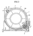
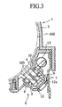
- FIGS. 1 to 7 there is shown a preferred embodiment of an ink bottle set-up device according to the present invention, wherein FIG. 1 is a cross sectional view of the ink bottle set-up device wherein an ink-bottle is located in an ink-bottle set-up starting position, FIG. 2 is a front view of the ink bottle set-up device showing a set-up condition of the ink bottle, FIG. 3 is an enlarged cross sectional view of an ink bottle erroneous set-up prevention mechanism, FIG. 4 is an enlarged cross sectional view of the ink-bottle erroneous set-up prevention mechanism, FIG. 5 is an exploded perspective view of the ink bottle erroneous set-up prevention mechanism , FIG.
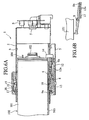
- FIG. 6A is a cross sectional view of the ink-bottle mounting device wherein the ink bottle is located in a halfway of an inserting stroke
- FIG. 6B is a part of a cross sectional view of the ink-bottle mounting device wherein an unsuitable ink bottle is located in a halfway of an inserting stroke
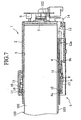
- FIG. 7 is a cross sectional view of the ink bottle set-up device wherein the ink bottle is located in a set-up position.
- the ink bottle 100 has been already described above in detail with reference to FIG. 8 and, therefore, a detailed description of the same is herein omitted for the sake of simplicity.
- the ink-bottle mounting device 1 includes a bottle set-up body 2 that has a bottle set-up chamber 3.
- the bottle set-up chamber 3 has a cylindrical configuration that has one distal end formed with an opening.
- the bottle set-up chamber 3 is designed to have a diameter slightly larger than that of the ink bottle 100 that is made of plastic and swells in outer diameter owing to an inherent property of material that absorbs an ink.
- the bottle set-up body 2 has a rib guide recess (or a projecting guide recess) 4 that is open to the bottle set-up chamber 3 and extends in a bottle set-up direction.
- the bottle set-up chamber 3 has an innermost end formed with an ink receptor portion 5, which is located in a central position of the bottle set-up chamber 3. Further, an information detecting sensor S is located in the innermost end of the bottle set-up chamber 3 in the vicinity of the ink receptor portion 5 in order to detect information such as a bottle-in or an ink color.
- the ink bottle set-up device 1 further includes an ink-bottle erroneous set-up prevention mechanism 6.
- the ink-bottle erroneous set-up prevention mechanism 6 includes a body bracket 7 secured to an outer periphery of the bottle set-up body 2 in the vicinity of the rib-guide recess 4, and a pair of detecting levers 9, as projection detecting members, rotatably supported by a pivot shaft 9 that is supported by the body bracket 7.
- each detecting lever 9 has a projection 9a that is located in an opening 10 formed in the bottle set-up body 2 and is freely moveable owing to the pivotal movement of the detecting lever 9 between a protruding position wherein the projection 9a is exposed to the rib guide recess 4 and a retracted position wherein the projection 9a is retracted from the rib guide recess 4.
- each of the detecting levers 9 has the other distal end to which one end of a leaf spring 11 is secured, with the other end of the leaf spring being held in abutting engagement with the bottle set-up body 2 such that the detecting levers 9 are urged toward the protruding position by the actions of the leaf springs 11, respectively.
- each detecting lever 9 has a stopper projection or claw 9b that is adapted to selectively engage with one of a series of engaging teeth 12a of a slide member 12 extending parallel to the outer periphery of the bottle set-up body 2 along an longitudinal axis thereof.
- the slide body 12 is disposed in the body bracket 7 for freely sliding movement along an axis parallel to a bottle set-up direction or a bottle discharging direction, and the series of engaging teeth 12a are formed on an upper surface of the slide body 12.
- One end of a tension spring 13 is connected to the other distal end of the slide member 12 and the other end of the tension spring 13 is connected to one distal end of the body bracket 7 such that the slide member 12 is urged toward the bottle discharging direction by an action of the tension spring 13.
- a bottle stopper segment 14 is firmly secured to the other distal end of the slide member 12 and extends inward in the bottle set-up chamber 3.
- a bottle stopper member is formed with the slide member 12 and the bottle stopper segment 14.
- the bottle set-up body 2 has a support member composed of an arm member 16 located in a position opposite to the ink-bottle erroneous set-up prevention mechanism 6, with the arm member 16 having one distal end that supports a biasing roller 17 for rotatable movement which serves as a part of a biasing member.
- the biasing roller 17 is freely moveable in a direction to allow the amount of projecting stroke of the biasing roller 17 to vary in the bottle set-up chamber 3 owing to the rotational movement of the arm member 16 and is urged inward in a protruding direction by the action of a twisted coil spring 18. That is, when the ink bottle 100 is inserted into the bottle set-up chamber 3, the outer periphery of the ink bottle 100 is urged toward an opposing side of the bottle set-up chamber 3.
- a correct ink bottle 100 having a positioning rib (i.e., a positioning projection) 103 is inserted into the bottle set-up body 2 in a suitably rotated orientation, the positioning rib 103 of the ink bottle 100 fits into the rib-guide recess 4 as viewed in FIG. 1. If, in this event, the ink bottle 100 is further inserted as shown in FIG.
- each detecting lever 9 is rotated from an initial protruding position toward the retracted position and a distal end of the ink bottle 100 is caused to abut against the bottle stopper segment 14.
- each stopper claw 9b of each detecting lever 9 is displaced from the opposing engaging teeth 12a, allowing the detecting levers 9 to move the slide member 12.
- the ink bottle 100 is caused to slide in a bottle set-up direction against the action of the tension spring 13 to allow a further inserting movement of the ink bottle 100. If, in this event, the ink bottle 100 is moved to a final rest or set-up position, the ink bottle 100 is locked in the final rest position, with a consequent set-up of the ink discharging section 102 of the ink bottle 100 relative to the ink receptor section 5 wherein the information indicating rib 104 is detected by the information detecting sensor S.
- the stopper claw 9b of the detecting lever 9 is brought into engagement with one of the series of the engaging teeth 12a by the actions of the leaf springs 11,11, preventing the slide member 12 from further sliding. Accordingly, even when the ink bottle 100 is inserted and the bottle stopper segment 14 is urged, the slide member 12 can not move in the sliding direction and, therefore, a further inserting movement of the ink bottle 100 is prevented by the bottle stopper segment 14.
- the primary advantage resides in that it is possible to prevent both undesired cases, namely, one for erroneous insertion of an incorrect ink bottle 100 with no positioning rib 103, and the other for erroneous insertion of the ink bottle 100 in unsuitably rotated orientation, for thereby avoiding influence caused in the information detecting sensor S due to undesired insertion of the unsuitable ink bottle 100 and its rotation.
- the ink bottle 100 can not be inserted in unsuitably rotated orientation, it is possible to prevent situation wherein the ink discharging section 102 of the ink bottle 100 and the ink receptor section 5 of the bottle set-up body 2 are set-up in a wrongly displaced condition, or wherein the information detecting sensor S can not correctly detect information from the ink body 100.
- Another advantage of the preferred embodiment of the present invention is that, when all of the two detecting levers (i.e. , the projection detecting member) 9 detect the positioning rib 103, discrimination is made wherein the positioning rib 103 is inserted into the rib-guide recess 4 and, when either one of the detecting levers 9 is moved toward the retracted position, the slide member 12 is not allowed for sliding movement, thereby preventing erroneous detection of the positioning rib 103 in a reliable fashion.
- the two detecting levers 9 are provided with respect to three rows of positioning ribs 103, three detecting levers 9 may be provided so as to correspond to three positioning ribs 103, thereby preventing the erroneous detection of the positioning ribs 103 in a further reliable manner.
- a single detecting lever 9 may also be provided with respect to the plural positioning ribs 103 and, further, the single detecting lever 9 may be provided with respect to a single positioning rib 103.
- Another advantage of the preferred embodiment of the present invention resides in that the ink bottle 100 is urged in the opposing direction by the action of the biasing roller 17 as a part of the biasing member to permit the positioning rib 103 of the ink bottle 100 to be correctly inserted into the rib-guide recess 4, thereby preventing erroneous detection of the positioning ribs 103. That is, although a consideration is undertaken to design the bottle set-up chamber 3 so as to have a diameter slightly larger than that of the ink bottle 100 to provide a margin in a space to some extent to compensate for an inherent property of swelling material owing to absorbing the ink, it is possible to prevent erroneous detection of the positioning ribs 103.
- a further advantage of the preferred embodiment of the present invention is the provision of the biasing member that is freely moveable in a direction to allow the amount of protruding stroke thereof to be varied in the bottle set-up chamber 3 and that includes the biasing roller 17 which is urged in the protruding direction and is freely rotatable.
- the ink bottle 100 is inserted into the bottle set-up chamber 3 while the biasing roller 17 rotates and urges the ink bottle 100 toward the rib-guide recess 4, inserting resistance is not imparted to the ink bottle 100 to permit smooth insertion of the ink bottle 100, provided that the biasing member is not limited to a particular structure employed in the preferred embodiment and may have other structure that allow the ink bottle 100 to be urged in the opposing direction in the bottle set-up chamber 3.
- a further advantage of the preferred embodiment of the present invention resides in that the projection detecting member is freely moveable between the protruding position wherein the projection protrudes into the rib-guide recess 4 and the retracted position wherein the projection is retracted from the rib-guide recess 4 and includes detecting levers 9 that are urged toward the protruding direction, thereby allowing the projection detecting member to be composed of only mechanical components.
- the projection detecting member is not limited to a particular structure employed in the preferred embodiment and may include other structure that can detect the positioning rib 103 which is correctly inserted into the rib-guide recess 4.
- a further advantage of the preferred embodiment of the present invention resides in the provision of a bottle stopper member that is freely moveable in the bottle set-up direction and the bottle discharging direction, that is urged in the bottle discharging direction and that includes a slide member 12 which is prevented from sliding movement when the detecting levers 9 remain in the protruding position and is allowed to slide when the detecting levers 4 remain in the retracted position, and the bottle stopper segment 14 extending into the bottle set-up chamber 3.
- the bottle stopper member may include only mechanical components, provided that the bottle stopper member is not limited to a particular structure employed in the preferred embodiment and may include other structure wherein, when the projection detecting member detects the positioning ribs 103 that is inserted in the rib-guide recess 4, the ink bottle 100 is allowed to insert the ink bottle 100 into the bottle set-up chamber 3 and, when the projection detecting member does not detect the positioning ribs 103, the ink bottle 100 is prevented from being inserted into the bottle set-up chamber 3.
- the single information indicating rib 104 and the single information detection sensor S are located in the ink bottle 100 and the bottle mounting device 1, respectively, plural information indicating ribs and plural information detection sensors may be utilized.
- the projection 104 is employed for indicating information of the ink bottle 100
- information of the ink bottle 100 may be indicated with the use of other components such as the detecting levers 9 formed with segments like the projections and urged for enabling positioning of the ink bottle 100.
Landscapes
- Inking, Control Or Cleaning Of Printing Machines (AREA)
- Ink Jet (AREA)
Claims (14)
- Einrichtung zum Aufstellen einer Tintenflasche (100), die einen Positioniervorsprung (103) hat, mit einem Flaschenaufstellkörper (2) mit einer Flaschenaufstellkammer (3) zur Aufnahme der Tintenflasche und einer Führungsausnehmung (4) zum Führen des Positioniervorsprungs führt,
gekennzeichnet durch
einen Mechanismus (6) zum Verhindern eines fehlerhaften Aufstellens der Tintenflasche, mit einem Vorsprungserfassungselement (9), das erfasst, dass der Positioniervorsprung in die Führungsausnehmung eingebracht worden ist, und einem Flaschenstopperelement (12, 14), das ein Einbringen der Tintenflasche in die Flaschenaufstellkammer hinein ermöglicht, wenn das Vorsprungserfassungselement erfasst, dass der Positioniervorsprung (103) in die Führungsausnehmung hineingebracht worden ist, um dadurch eine Aufstellung der Tintenflasche in einer gegebenen Position der Aufstellkammer zu ermöglichen, wobei das Flaschenstopperelement (12, 14) ein Einbringen der Tintenflasche in die Flaschenaufstellkammer hinein verhindert, wenn das Vorsprungserfassungselement (9) erfasst, dass der Positioniervorsprung (103) nicht in Ausrichtung mit der Führungsausnehmung (4) ist. - Einrichtung nach Anspruch 1, bei welcher der Positioniervorsprung sich entlang einer Einführrichtung der Tintenflasche erstreckt.
- Einrichtung nach Anspruch 1, bei welcher die Führungsausnehmung für den Vorsprung entlang der Einführrichtung der Tintenflasche in dem Flaschenaufstellkörper ausgebildet ist und sich hin zu der Flaschenaufstellkammer öffnet.
- Einrichtung nach Anspruch 1, bei welcher das Vorsprungserfassungselement einen Erfassungshebel (9) hat, der frei durch die Führungsausnehmung hindurch zwischen einer hervorstehenden und einer zurückgezogenen Position beweglich ist.
- Einrichtung nach Anspruch 4, bei welcher der Erfassungshebel mittels eines Federelements (11) in Richtung der hervorstehenden Position beaufschlagt wird.
- Einrichtung nach Anspruch 1, bei welcher das Flaschenstopperelement ein Schieberelement (14) hat, das frei in einer Einführrichtung der Tintenflasche und in einer Ausbringrichtung der Tintenflasche beweglich ist, so dass, wenn der Erfassungshebel in der hervorstehenden Position verbleibt, eine gleitende Bewegung des Schieberelements verhindert ist, und, wenn der Erfassungshebel in der zurückgezogenen Position verbleibt, das Schieberelement sich verschieben kann; und ein Flaschenstoppersegment (14), das an dem Schieberelement fest gesichert ist und in die Flaschenaufstellkammer hinein hervorsteht.
- Einrichtung nach Anspruch 6, bei welcher das Schieberelement in der Ausgaberichtung der Tintenflasche mittels eines Federelements (13) beaufschlagt ist.
- Einrichtung nach Anspruch 1, bei welcher der Positioniervorsprung mehrere Positionierrippen (103) hat, und das Vorsprungserfassungselement mehrere Erfassungselemente hat, deren Anzahl gleich der der Positionierrippen ist.
- Einrichtung nach Anspruch 1, bei welcher ein Vorspannelement (17) vorgesehen ist, welches die Tintenflasche in Richtung des Mechanismus zum Verhindern eines fehlerhaften Aufstellens der Tintenflasche beaufschlagt.
- Einrichtung nach Anspruch 9, bei welcher das Vorspannelement sich in der Flaschenaufstellkammer in einer Position gegenüber dem Mechanismus zum Verhindern des fehlerhaften Aufstellens der Tintenflasche befindet.
- Einrichtung nach Anspruch 10, bei welcher das Vorspannelement eine drehbare Walze (17) hat, die in der Flaschenaufstellkammer hervorsteht, und ein Stützelement, das die drehbare Walze so lagert, dass die drehbare Walze sich in einer Richtung frei bewegt, in der die drehbare Walze in der Flaschenaufstellkammer mit einem variablen hervorstehenden Hub hervorstehen kann.
- Einrichtung nach Anspruch 11, bei welcher die drehbare Walze in Richtung einer hervorstehenden Richtung mittels eines Federelements beaufschlagt ist.
- Einrichtung nach Anspruch 1, bei welcher die Tintenflasche eine Bodenwand hat, in welcher ein Tintenausgabeabschnitt ausgebildet ist, und der Flaschenaufstellkörper einen Tintenaufnahmeabschnitt (5) hat, mit welchem der Tintenausgabeabschnitt gekoppelt ist, wenn die Tintenflasche in der gegebenen Position der Flaschenaufstellkammer aufgestellt ist.
- Einrichtung nach Anspruch 1, bei welcher die Tintenflasche eine Informationen anzeigende Rippe (104) hat, und der Flaschenaufstellkörper einen Informationserfassungssensor (S) zum Erfassen der Informationen anzeigenden Rippe hat.
Applications Claiming Priority (2)
| Application Number | Priority Date | Filing Date | Title |
|---|---|---|---|
| JP2000044895 | 2000-02-22 | ||
| JP2000044895A JP3790084B2 (ja) | 2000-02-22 | 2000-02-22 | インクボトル装着装置 |
Publications (3)
| Publication Number | Publication Date |
|---|---|
| EP1127704A2 EP1127704A2 (de) | 2001-08-29 |
| EP1127704A3 EP1127704A3 (de) | 2002-09-11 |
| EP1127704B1 true EP1127704B1 (de) | 2005-11-09 |
Family
ID=18567586
Family Applications (1)
| Application Number | Title | Priority Date | Filing Date |
|---|---|---|---|
| EP01102845A Expired - Lifetime EP1127704B1 (de) | 2000-02-22 | 2001-02-13 | Tintenflaschenmontiervorrichtung |
Country Status (5)
| Country | Link |
|---|---|
| US (1) | US6530503B2 (de) |
| EP (1) | EP1127704B1 (de) |
| JP (1) | JP3790084B2 (de) |
| CN (1) | CN1199792C (de) |
| DE (1) | DE60114677T2 (de) |
Families Citing this family (1)
| Publication number | Priority date | Publication date | Assignee | Title |
|---|---|---|---|---|
| CN115628660B (zh) * | 2022-09-29 | 2023-10-10 | 江苏华培动力科技有限公司 | 一种带有防护装置的涡轮增压器中间壳防错工装 |
Family Cites Families (9)
| Publication number | Priority date | Publication date | Assignee | Title |
|---|---|---|---|---|
| US3685694A (en) * | 1969-12-18 | 1972-08-22 | Yan Nell Corp | Liquid dispenser plastic bottle and receptacle with piercing units |
| US5100030A (en) * | 1990-05-24 | 1992-03-31 | Inopak Ltd. | Fixtures for fluid dispensing bags |
| US5174476A (en) * | 1991-05-06 | 1992-12-29 | Steiner Company, Inc. | Liquid soap dispensing system |
| US5261568A (en) * | 1992-02-14 | 1993-11-16 | Eastman Kodak Company | Apparatus for storing and dispensing pigmented marking particles |
| JPH08142307A (ja) * | 1994-11-16 | 1996-06-04 | Riso Kagaku Corp | 輪転式印刷機のインキ容器保持装置 |
| US5613625A (en) * | 1995-03-31 | 1997-03-25 | Waterbury Companies, Inc. | Anticounterfeit device for dispenser |
| US6095370A (en) * | 1997-12-18 | 2000-08-01 | Americlean Systems, Inc. | Encapsulated liquid dispensing device and method |
| US6283330B1 (en) * | 1999-08-25 | 2001-09-04 | The Butcher Company | Cleaning solution dilution and dispensing system |
| US6412666B1 (en) * | 2001-03-19 | 2002-07-02 | International Business Machines Corporation | Fluid container with a keying means to prevent improper fluid loading in a fluid delivery tool and a system including such fluid container and fluid delivery tool |
-
2000
- 2000-02-22 JP JP2000044895A patent/JP3790084B2/ja not_active Expired - Fee Related
-
2001
- 2001-02-13 DE DE60114677T patent/DE60114677T2/de not_active Expired - Fee Related
- 2001-02-13 EP EP01102845A patent/EP1127704B1/de not_active Expired - Lifetime
- 2001-02-14 US US09/782,221 patent/US6530503B2/en not_active Expired - Lifetime
- 2001-02-22 CN CN01103840.3A patent/CN1199792C/zh not_active Expired - Fee Related
Also Published As
| Publication number | Publication date |
|---|---|
| DE60114677D1 (de) | 2005-12-15 |
| JP2001232763A (ja) | 2001-08-28 |
| DE60114677T2 (de) | 2006-07-20 |
| US6530503B2 (en) | 2003-03-11 |
| JP3790084B2 (ja) | 2006-06-28 |
| EP1127704A3 (de) | 2002-09-11 |
| US20010015146A1 (en) | 2001-08-23 |
| CN1310099A (zh) | 2001-08-29 |
| CN1199792C (zh) | 2005-05-04 |
| EP1127704A2 (de) | 2001-08-29 |
Similar Documents
| Publication | Publication Date | Title |
|---|---|---|
| KR100324099B1 (ko) | 신뢰성 있는 커버스위치를 사용한 장치 | |
| US7437119B2 (en) | Image forming apparatus and feeding tray | |
| KR970064963A (ko) | 프린터 | |
| RU2556505C2 (ru) | Удерживающий механизм в выдачном устройстве для удерживания сменного рулона материала, удерживающая система, выдачное устройство и способ вставки рулона материала в такой удерживающий механизм | |
| EP1127704B1 (de) | Tintenflaschenmontiervorrichtung | |
| EP1961612A2 (de) | Schaltervorrichtung für eine Fahrtrichtungsanzeige | |
| EP1434166B1 (de) | Kartenleser | |
| JP4276835B2 (ja) | スイッチ | |
| JP3840920B2 (ja) | 給紙装置 | |
| US5018885A (en) | Cassette for a printing ribbon for typewriters | |
| US4925076A (en) | Paper feeder | |
| KR100288535B1 (ko) | 자동차 시트의 높이조절수단 잠금장치 | |
| CN216526744U (zh) | 一种显影盒 | |
| JP7525376B2 (ja) | リッド開閉装置 | |
| JP6547713B2 (ja) | シート収納装置 | |
| US5790507A (en) | Cartridge changing device | |
| JP3696061B2 (ja) | プリンタ | |
| WO2006079158A1 (en) | Usage indicator for a cartridge | |
| US5524744A (en) | Coin return mechanism for a coin acceptor | |
| CN112497936B (zh) | 纸宽侦测组件以及具有该组件的打印机 | |
| CN223880977U (zh) | 一种地弹簧 | |
| JP6819728B2 (ja) | シート収納装置及び画像形成装置 | |
| US6679447B2 (en) | Seat belt retractor | |
| JP2882025B2 (ja) | 磁気テープカセット | |
| JP6873573B2 (ja) | ヒンジ装置 |
Legal Events
| Date | Code | Title | Description |
|---|---|---|---|
| PUAI | Public reference made under article 153(3) epc to a published international application that has entered the european phase |
Free format text: ORIGINAL CODE: 0009012 |
|
| 17P | Request for examination filed |
Effective date: 20010213 |
|
| AK | Designated contracting states |
Kind code of ref document: A2 Designated state(s): AT BE CH CY DE DK ES FI FR GB GR IE IT LI LU MC NL PT SE TR |
|
| AX | Request for extension of the european patent |
Free format text: AL;LT;LV;MK;RO;SI |
|
| PUAL | Search report despatched |
Free format text: ORIGINAL CODE: 0009013 |
|
| AK | Designated contracting states |
Kind code of ref document: A3 Designated state(s): AT BE CH CY DE DK ES FI FR GB GR IE IT LI LU MC NL PT SE TR |
|
| AX | Request for extension of the european patent |
Free format text: AL;LT;LV;MK;RO;SI |
|
| RIC1 | Information provided on ipc code assigned before grant |
Free format text: 7B 41L 13/18 A, 7B 41L 27/04 B, 7B 41F 31/02 B |
|
| AKX | Designation fees paid |
Designated state(s): DE FR GB |
|
| GRAP | Despatch of communication of intention to grant a patent |
Free format text: ORIGINAL CODE: EPIDOSNIGR1 |
|
| GRAS | Grant fee paid |
Free format text: ORIGINAL CODE: EPIDOSNIGR3 |
|
| GRAA | (expected) grant |
Free format text: ORIGINAL CODE: 0009210 |
|
| AK | Designated contracting states |
Kind code of ref document: B1 Designated state(s): DE FR GB |
|
| REG | Reference to a national code |
Ref country code: GB Ref legal event code: FG4D |
|
| REF | Corresponds to: |
Ref document number: 60114677 Country of ref document: DE Date of ref document: 20051215 Kind code of ref document: P |
|
| ET | Fr: translation filed | ||
| PLBE | No opposition filed within time limit |
Free format text: ORIGINAL CODE: 0009261 |
|
| STAA | Information on the status of an ep patent application or granted ep patent |
Free format text: STATUS: NO OPPOSITION FILED WITHIN TIME LIMIT |
|
| 26N | No opposition filed |
Effective date: 20060810 |
|
| PGFP | Annual fee paid to national office [announced via postgrant information from national office to epo] |
Ref country code: DE Payment date: 20090206 Year of fee payment: 9 |
|
| PGFP | Annual fee paid to national office [announced via postgrant information from national office to epo] |
Ref country code: GB Payment date: 20090211 Year of fee payment: 9 |
|
| PGFP | Annual fee paid to national office [announced via postgrant information from national office to epo] |
Ref country code: FR Payment date: 20090213 Year of fee payment: 9 |
|
| GBPC | Gb: european patent ceased through non-payment of renewal fee |
Effective date: 20100213 |
|
| REG | Reference to a national code |
Ref country code: FR Ref legal event code: ST Effective date: 20101029 |
|
| PG25 | Lapsed in a contracting state [announced via postgrant information from national office to epo] |
Ref country code: FR Free format text: LAPSE BECAUSE OF NON-PAYMENT OF DUE FEES Effective date: 20100301 |
|
| PG25 | Lapsed in a contracting state [announced via postgrant information from national office to epo] |
Ref country code: DE Free format text: LAPSE BECAUSE OF NON-PAYMENT OF DUE FEES Effective date: 20100901 |
|
| PG25 | Lapsed in a contracting state [announced via postgrant information from national office to epo] |
Ref country code: GB Free format text: LAPSE BECAUSE OF NON-PAYMENT OF DUE FEES Effective date: 20100213 |