EP1126500A2 - Kathodenstrahlröhre - Google Patents
Kathodenstrahlröhre Download PDFInfo
- Publication number
- EP1126500A2 EP1126500A2 EP01103396A EP01103396A EP1126500A2 EP 1126500 A2 EP1126500 A2 EP 1126500A2 EP 01103396 A EP01103396 A EP 01103396A EP 01103396 A EP01103396 A EP 01103396A EP 1126500 A2 EP1126500 A2 EP 1126500A2
- Authority
- EP
- European Patent Office
- Prior art keywords
- shadow mask
- slit
- ray tube
- cathode ray
- apertures
- Prior art date
- Legal status (The legal status is an assumption and is not a legal conclusion. Google has not performed a legal analysis and makes no representation as to the accuracy of the status listed.)
- Withdrawn
Links
Images


Classifications
-
- H—ELECTRICITY
- H01—ELECTRIC ELEMENTS
- H01J—ELECTRIC DISCHARGE TUBES OR DISCHARGE LAMPS
- H01J29/00—Details of cathode-ray tubes or of electron-beam tubes of the types covered by group H01J31/00
- H01J29/02—Electrodes; Screens; Mounting, supporting, spacing or insulating thereof
- H01J29/06—Screens for shielding; Masks interposed in the electron stream
- H01J29/07—Shadow masks for colour television tubes
-
- H—ELECTRICITY
- H01—ELECTRIC ELEMENTS
- H01J—ELECTRIC DISCHARGE TUBES OR DISCHARGE LAMPS
- H01J2229/00—Details of cathode ray tubes or electron beam tubes
- H01J2229/07—Shadow masks
- H01J2229/0727—Aperture plate
- H01J2229/0738—Mitigating undesirable mechanical effects
Definitions
- the present invention relates to a shadow mask type cathode ray tube, which is used for a television receiver, a computer display, and the like.
- FIG. 4 is a cross-sectional view showing one example of a conventional color cathode ray tube.
- the color cathode ray tube 41 shown in FIG. 4 includes a substantially rectangular-shaped face panel 42 having a phosphor screen formed on its inner face, a funnel 43 connected to the rear side of the face panel 42, an electron gun 44 contained in a neck portion 43a of the funnel 43, a shadow mask 46 facing the phosphor screen 42a inside the face panel 42, and a mask frame 47 for fixing the shadow mask 46.
- a deflection yoke 45 is provided on the outer periphery of the funnel 43.
- the shadow mask 46 plays a role of selecting colors with respect to three electron beams emitted from the electron gun 44. "A" shows a track of the electron beams.
- the shadow mask is a flat plate in which a number of apertures, through which electron beams pass, are formed by etching.
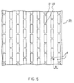
- FIG. 5 is a plan view showing a part of an example of a conventional shadow mask.
- a shadow mask 20 In a shadow mask 20, a number of apertures 21 are formed in lines. The apertures 21 neighboring in the vertical direction (vertical direction of the screen) are connected by a bridge 22.
- stress is applied in the direction indicated by arrow d. When such stress is applied, wrinkles are created in the area B, and the aperture 21 is shifted in the horizontal direction.
- a so-called local doming phenomenon occurs, electron beams do not hit the shadow mask correctly, thus causing displacement of colors, unevenness in colors, and deterioration of luminance.
- the thickness of the shadow mask is extremely small (for example, about 0.1mm) compared to the thickness of the mask frame to which the shadow mask is fixed. Therefore, in the initial stage of operating the color cathode ray tube, a so-called initial doming phenomenon occurs, in which only the shadow mask expands thermally. When this initial doming phenomenon occurs, the lines of the aperture are shifted in the horizontal direction, so that electron beams do not hit the shadow mask correctly, thus causing displacement of colors, unevenness in colors, and deterioration of luminance. Such problems caused by the local doming phenomenon or the initial doming phenomenon could not be prevented sufficiently even by stretching and holding the shadow mask as described above.
- the cathode ray tube of the present invention is characterized by including a shadow mask made of a flat plate in which a number of aperture lines are arranged, wherein a slit extending in the line direction of the apertures is formed between the neighboring aperture lines.
- the slit includes a slit having inclined faces opposed to each other via an opening, and the inclined faces are formed at an angle inclined such that electron beams entering the shadow mask are blocked.
- the slit described above includes a slit having inclined faces opposed to each other via an opening, and the inclined faces are inclined toward the side of a vertical center line of the shadow mask by taking a rear face of the shadow mask as the starting point.
- the cathode ray tube including the shadow mask provided with the slit having inclined faces as described above electron beams are blocked surely in the portion where the slit is formed. Therefore, while incorrect hitting of electron beams can be prevented, with regard to passing of electron beams, this shadow mask is substantially equivalent to a shadow mask in which a slit is not formed.
- a connected portion is further provided for linking the inclined faces opposed to each other at one portion of each inclined face. According to the cathode ray tube described above, electron beams are blocked even more surely in the portion where the slit is formed.
- a plurality of slits described above preferably are formed separately in the line direction of the apertures.
- a number of bridge for linking upper and lower slits is increased, so that the hardness of the shadow mask can be secured more easily, and at the same time, the surfaces of the shadow mask located on the right and left sides of the slits are less likely to be entwined.
- FIG. 1 is a perspective view showing a color-selecting electrode of one embodiment of the present invention.
- FIG. 2 is a plan view showing a shadow mask of one embodiment of the present invention.
- FIG. 3A is a cross-sectional view taken on line I-I of FIG. 2.
- FIG. 3B is a cross-sectional view taken on line II-II of FIG. 2.
- FIG. 4 is a cross-sectional view showing an example of a color cathode ray tube.
- FIG. 5 is a plan view showing an example of a conventional shadow mask.
- FIG. 1 is a perspective view showing one embodiment of a color-selecting electrode.
- a mask frame 30 is a rectangular frame and is made of a pair of long frame supports 31, facing each other, fixed to a pair of short frames made of elastic members 32.
- the shadow mask 1 is held between the supports 31.
- apertures 2, through which electron beams pass, are formed by etching.
- a slit 5 is formed between the lines of the apertures 2.
- a tension method is employed, and the shadow mask 1 is stretched and held between the supports 31 with a tension force applied mainly in the direction indicated by arrow Y.
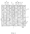
- FIG. 2 is a plan view showing a part of one embodiment of a shadow mask according to the present invention.
- a number of apertures 2 are formed in lines, and the apertures 2 neighboring in the vertical direction of the shadow mask 1 (vertical direction of the screen) are linked by a bridge 3.
- a line 4 shows the vertical center line of the shadow mask 1.
- the slit 5 is formed in the right area (hereinafter, this area is referred to as "right area”) and a slit 6 is formed in the left area (hereinafter, this area is referred to as "left area”) respectively.
- the slits 5, 6 are formed between the neighboring lines of the apertures 2.
- the slit 5 is formed between an aperture line 2a and an aperture line 2b in the right area
- the slit 6 is formed between an aperture line 2c and an aperture line 2d in the left area.
- Such slits can be formed by etching just like forming the apertures 2, and they also can be formed by laser processing.
- the slits 5, 6 neighboring in the vertical direction are linked by a bridge 7.
- FIG. 3 is a cross-sectional view of the shadow mask shown in FIG. 2 taken in the horizontal direction (horizontal direction of the screen).
- FIG. 3A is a cross-sectional view taken on line I-I of FIG. 2, that is, a cross-sectional view in the right area
- FIG. 3B is a cross-sectional view taken on line II-II of FIG. 2, that is, a cross-sectional view in the left area.
- the slit 5 in the right area has an inclined face 8 and an inclined face 9 opposed to each other via an opening 10.
- the inclined faces 8, 9 start to incline from a rear face 1b of the shadow mask 1 and incline toward the side of the vertical center line 4 as they approach a surface la.
- the slit 6 in the left area has an inclined face 11 and an inclined face 12 opposed to each other via an opening 13.
- the inclined faces 11, 12 start to incline from the rear face 1b of the shadow mask 1 and incline toward the side of the vertical center line 4 as they approach the surface 1a.
- the slit 5 is formed between the lines of the apertures 2, so that such stress is effected in the direction of reducing the width of the slit 5 and is absorbed by the deformation of the slit 5.
- the present embodiment it is possible to suppress the displacement of apertures due to the local doming phenomenon or the initial doming phenomenon caused by the thermal expansion of the shadow mask. As a result, displacement of colors, unevenness in colors, and deterioration of luminance caused by incorrect hitting of electron beams can be prevented from occurring.
- FIG. 3A electron beams are propagated in the direction indicated by arrow a in the right area.
- a light beam 14 passes through the aperture 2, but a light beam 15 is blocked by the inclined face 9 of the slit 5.
- This configuration also applies to the left area.
- FIG. 3B electron beams are propagated in the direction indicated by arrow b in the left area.
- a light beam 16 passes through the aperture 2, but a light beam 17 is blocked by the inclined face 12 of the slit 6.
- this shadow mask is substantially equivalent to a shadow mask in which the slits are not formed.
- a thickness t of the shadow mask preferably is in the range between 0.05 and 0.25mm
- a width C of the aperture preferably is in the range between 0.7t and 2t
- a width D preferably is in the range between 1.2C and 2.5C
- a width E of the slit preferably is in the range between 0.1t and 0.8t.
- the slit was explained by referring to the case in which the slit penetrates completely from the surface to the rear face of the shadow mask, but there also may be a minute connected portion 23 formed in the opening for linking the opposed inclined faces as illustrated in FIG. 3C. Also in this case, the effect of absorbing stress can be achieved, and light is blocked even more surely.
- the connected portion 23 may be formed successively over the entire slits and also partially or intermittently. It may be determined appropriately in the range in which both the effect of absorbing stress and the shielding effect can be achieved at the same time.
- the inclined angle of the slit is not limited to the example illustrated in FIG. 3.
- the inclined angle may be determined suitably in the range in which stress can be absorbed and electron beams can be blocked.
- the inclined direction of the slit may be determined to be opposite to the example illustrated in FIG. 3. Namely, as for the direction of inclination of the inclined faces, the inclined faces may start to incline from the rear face 1b of the shadow mask 1 and incline toward the side away from the vertical center line 4 as they approach the surface 1a.
- the slit also may be formed with the vertical faces opposed to each other.
- each line may be formed as one slit.
- the present embodiment was described under the condition that the shadow mask is stretched and held. However, even if the shadow mask is not stretched and held, the effect of absorbing stress as described above can be obtained. Therefore, the present embodiment also is applicable to a shadow mask provided with a curved surface formed by press molding, which is not stretched and held.
- the slit 5 is formed between the lines of the apertures 2, but the slit 5 may be further provided in the area between the lines of the apertures 2 on the both sides and the right and left edges of the shadow mask.
- the cathode ray tube of the present invention in the shadow mask made of a flat plate in which a number of aperture lines are arranged, a slit is formed between the neighboring aperture lines.
- the displacement of apertures due to the local doming phenomenon or the initial doming phenomenon caused by the thermal expansion of the shadow mask can be suppressed.
- displacement of colors, unevenness in colors, and deterioration of luminance caused by incorrect hitting of electron beams can be prevented from occurring.
Landscapes
- Electrodes For Cathode-Ray Tubes (AREA)
Applications Claiming Priority (2)
| Application Number | Priority Date | Filing Date | Title |
|---|---|---|---|
| JP2000040007 | 2000-02-17 | ||
| JP2000040007 | 2000-02-17 |
Publications (2)
| Publication Number | Publication Date |
|---|---|
| EP1126500A2 true EP1126500A2 (de) | 2001-08-22 |
| EP1126500A3 EP1126500A3 (de) | 2002-05-15 |
Family
ID=18563476
Family Applications (1)
| Application Number | Title | Priority Date | Filing Date |
|---|---|---|---|
| EP01103396A Withdrawn EP1126500A3 (de) | 2000-02-17 | 2001-02-14 | Kathodenstrahlröhre |
Country Status (4)
| Country | Link |
|---|---|
| US (1) | US6548950B2 (de) |
| EP (1) | EP1126500A3 (de) |
| KR (1) | KR100390270B1 (de) |
| CN (1) | CN1145186C (de) |
Cited By (2)
| Publication number | Priority date | Publication date | Assignee | Title |
|---|---|---|---|---|
| EP1178515A2 (de) * | 2000-08-04 | 2002-02-06 | Matsushita Electric Industrial Co., Ltd. | Kathodenstrahlröhre |
| EP1372180A2 (de) * | 2002-06-12 | 2003-12-17 | Matsushita Electric Industrial Co., Ltd. | Kathodenstrahlröhre |
Families Citing this family (2)
| Publication number | Priority date | Publication date | Assignee | Title |
|---|---|---|---|---|
| KR100334081B1 (ko) * | 2000-07-12 | 2002-04-26 | 김순택 | 칼라 음극선관용 마스크 |
| KR100786827B1 (ko) * | 2001-06-08 | 2007-12-20 | 삼성에스디아이 주식회사 | 음극선관의 색 선별 장치 |
Citations (4)
| Publication number | Priority date | Publication date | Assignee | Title |
|---|---|---|---|---|
| JPS59194332A (ja) * | 1983-04-20 | 1984-11-05 | Toshiba Corp | カラ−受像管 |
| US4636683A (en) * | 1983-03-10 | 1987-01-13 | Tokyo Shibaura Denki Kabushiki Kaisha | Color cathode-ray tube having shadow mask with variable sized apertures |
| US4727280A (en) * | 1984-03-30 | 1988-02-23 | Mitsubishi Denki Kabushiki Kaisha | Shadow mask for color cathode ray tube shaped to minimize doming |
| EP0939424A2 (de) * | 1998-02-26 | 1999-09-01 | Matsushita Electronics Corporation | Farbbildröhre |
-
2001
- 2001-02-13 US US09/782,208 patent/US6548950B2/en not_active Expired - Fee Related
- 2001-02-14 EP EP01103396A patent/EP1126500A3/de not_active Withdrawn
- 2001-02-16 KR KR10-2001-0007725A patent/KR100390270B1/ko not_active IP Right Cessation
- 2001-02-19 CN CNB011047321A patent/CN1145186C/zh not_active Expired - Fee Related
Patent Citations (4)
| Publication number | Priority date | Publication date | Assignee | Title |
|---|---|---|---|---|
| US4636683A (en) * | 1983-03-10 | 1987-01-13 | Tokyo Shibaura Denki Kabushiki Kaisha | Color cathode-ray tube having shadow mask with variable sized apertures |
| JPS59194332A (ja) * | 1983-04-20 | 1984-11-05 | Toshiba Corp | カラ−受像管 |
| US4727280A (en) * | 1984-03-30 | 1988-02-23 | Mitsubishi Denki Kabushiki Kaisha | Shadow mask for color cathode ray tube shaped to minimize doming |
| EP0939424A2 (de) * | 1998-02-26 | 1999-09-01 | Matsushita Electronics Corporation | Farbbildröhre |
Non-Patent Citations (1)
| Title |
|---|
| PATENT ABSTRACTS OF JAPAN vol. 009, no. 053 (E-301), 7 March 1985 (1985-03-07) & JP 59 194332 A (TOSHIBA KK), 5 November 1984 (1984-11-05) * |
Cited By (5)
| Publication number | Priority date | Publication date | Assignee | Title |
|---|---|---|---|---|
| EP1178515A2 (de) * | 2000-08-04 | 2002-02-06 | Matsushita Electric Industrial Co., Ltd. | Kathodenstrahlröhre |
| EP1178515A3 (de) * | 2000-08-04 | 2002-02-13 | Matsushita Electric Industrial Co., Ltd. | Kathodenstrahlröhre |
| US6710527B2 (en) | 2000-08-04 | 2004-03-23 | Matsushita Electric Industrial Co., Ltd. | Cathode ray tube with slit in dead space of shadow mask |
| EP1372180A2 (de) * | 2002-06-12 | 2003-12-17 | Matsushita Electric Industrial Co., Ltd. | Kathodenstrahlröhre |
| EP1372180A3 (de) * | 2002-06-12 | 2007-11-28 | Matsushita Electric Industrial Co., Ltd. | Kathodenstrahlröhre |
Also Published As
| Publication number | Publication date |
|---|---|
| KR20010088337A (ko) | 2001-09-26 |
| CN1309411A (zh) | 2001-08-22 |
| CN1145186C (zh) | 2004-04-07 |
| EP1126500A3 (de) | 2002-05-15 |
| US6548950B2 (en) | 2003-04-15 |
| US20010015607A1 (en) | 2001-08-23 |
| KR100390270B1 (ko) | 2003-07-04 |
Similar Documents
| Publication | Publication Date | Title |
|---|---|---|
| KR970008560B1 (ko) | 칼라 수상관 | |
| KR100354245B1 (ko) | 음극선관용 텐션 마스크 | |
| US6710527B2 (en) | Cathode ray tube with slit in dead space of shadow mask | |
| EP0655762A1 (de) | Farbkathodenstrahlröhre | |
| US6455991B2 (en) | Cathode ray tube with shadow mask | |
| EP1126500A2 (de) | Kathodenstrahlröhre | |
| US6388370B1 (en) | Cathode ray tube | |
| EP0982755B1 (de) | Schattenmaske für eine Farb-Kathodenstrahlröhre | |
| US6614153B2 (en) | Mask for color picture tube | |
| JP3878814B2 (ja) | 陰極線管 | |
| US6577047B2 (en) | Cathode ray tube | |
| EP1117120B1 (de) | Kathodenstrahlröhre | |
| US6600258B2 (en) | Tension mask for a cathode-ray-tube | |
| JP3981254B2 (ja) | 陰極線管 | |
| KR200187377Y1 (ko) | 음극선관용 마스크 어셈블리 | |
| JP2001084918A (ja) | 陰極線管 | |
| JPH07230772A (ja) | カラー陰極線管 | |
| JP2004273170A (ja) | カラー陰極線管 | |
| US20040217683A1 (en) | Color cathode ray tube and mask assembly for same | |
| JP2001185048A (ja) | 陰極線管 | |
| JP2002110060A (ja) | シャドウマスク構体及びカラー受像管 | |
| KR20030091577A (ko) | 컬러 음극선관용 마스크 조립체 | |
| KR20030088962A (ko) | 컬러 음극선관용 마스크 조립체 | |
| JPH07335140A (ja) | カラー受像管 | |
| JPH0729525A (ja) | カラー受像管 |
Legal Events
| Date | Code | Title | Description |
|---|---|---|---|
| PUAI | Public reference made under article 153(3) epc to a published international application that has entered the european phase |
Free format text: ORIGINAL CODE: 0009012 |
|
| AK | Designated contracting states |
Kind code of ref document: A2 Designated state(s): AT BE CH CY DE DK ES FI FR GB GR IE IT LI LU MC NL PT SE TR |
|
| AX | Request for extension of the european patent |
Free format text: AL;LT;LV;MK;RO;SI |
|
| RAP1 | Party data changed (applicant data changed or rights of an application transferred) |
Owner name: MATSUSHITA ELECTRIC INDUSTRIAL CO., LTD. |
|
| PUAL | Search report despatched |
Free format text: ORIGINAL CODE: 0009013 |
|
| AK | Designated contracting states |
Kind code of ref document: A3 Designated state(s): AT BE CH CY DE DK ES FI FR GB GR IE IT LI LU MC NL PT SE TR |
|
| AX | Request for extension of the european patent |
Free format text: AL;LT;LV;MK;RO;SI |
|
| 17P | Request for examination filed |
Effective date: 20020529 |
|
| AKX | Designation fees paid |
Designated state(s): DE FR GB IT NL |
|
| 17Q | First examination report despatched |
Effective date: 20031106 |
|
| RAP1 | Party data changed (applicant data changed or rights of an application transferred) |
Owner name: PANASONIC CORPORATION |
|
| GRAP | Despatch of communication of intention to grant a patent |
Free format text: ORIGINAL CODE: EPIDOSNIGR1 |
|
| STAA | Information on the status of an ep patent application or granted ep patent |
Free format text: STATUS: THE APPLICATION IS DEEMED TO BE WITHDRAWN |
|
| 18D | Application deemed to be withdrawn |
Effective date: 20100222 |