EP1126227A1 - Steam condenser - Google Patents
Steam condenser Download PDFInfo
- Publication number
- EP1126227A1 EP1126227A1 EP00810112A EP00810112A EP1126227A1 EP 1126227 A1 EP1126227 A1 EP 1126227A1 EP 00810112 A EP00810112 A EP 00810112A EP 00810112 A EP00810112 A EP 00810112A EP 1126227 A1 EP1126227 A1 EP 1126227A1
- Authority
- EP
- European Patent Office
- Prior art keywords
- steam
- condenser
- modules
- space
- neck
- Prior art date
- Legal status (The legal status is an assumption and is not a legal conclusion. Google has not performed a legal analysis and makes no representation as to the accuracy of the status listed.)
- Withdrawn
Links
Images


Classifications
-
- F—MECHANICAL ENGINEERING; LIGHTING; HEATING; WEAPONS; BLASTING
- F28—HEAT EXCHANGE IN GENERAL
- F28B—STEAM OR VAPOUR CONDENSERS
- F28B1/00—Condensers in which the steam or vapour is separate from the cooling medium by walls, e.g. surface condenser
- F28B1/02—Condensers in which the steam or vapour is separate from the cooling medium by walls, e.g. surface condenser using water or other liquid as the cooling medium
Definitions
- the invention relates to a steam condenser in a steam power plant or Combined system, which is arranged at ground level with the turbine and to which the Turbine steam flows in a horizontal direction through a condenser neck.
- the steam condenser has several elongated and horizontal stored tube bundles, each separated by a central aisle are spaced and through which the steam flows into the tube bundle.
- a device arranged for the introduction of steam, from the boiler of the power plant via a bypass line directly into the Condenser is passed.
- Such a steam condenser with horizontal steam inflow is described for example in EP 0 384 200. It has several elongated and horizontally arranged bundles of pipes through which the cooling water flows.
- the steam flows in from the turbine in a horizontal direction via the condenser neck into the Mittelgasse and from there into the interior of the tube bundle, where the steam condenses.
- the condensate that forms on the pipes flows down through condensate collecting plates into a hotwell in the area of the bottom of the condenser.
- such a steam condenser is of modular construction, with each module containing, for example, two tube bundles, between which there is a free space or a central lane through which the steam can reach the cooling tubes in the tube bundles.
- the modules are arranged one above the other, their central, horizontal module walls, which face an adjacent module, being connected to one another by assembly weld seams.
- the condensate that accumulates in the tube bundles of the upper module flows to an opening at the bottom of that module. From there it finally gets into the lower module and into the hotwell of the capacitor.
- the welded connection between the middle module walls bears the risk that a gap can occur along these module walls due to manufacturing tolerances. As a result, the contact areas there are irregular and there are uneven tensions. These can lead to leaks and create a risk of corrosion, especially in the area of the drain opening for the condensate from the upper to the lower module. Since the module walls lie directly on top of each other, this corrosion cannot be inspected visually and a repair can be arranged if necessary.
- a steam bypass station When starting up and shutting down a power plant and when shedding loads, steam from the boiler is fed directly to the condenser via a steam bypass station for operational safety and to reduce losses.
- a diversion station typically consists of two to three bypass lines that bypass the turbine and a steam introduction device in the condenser neck.
- the mass flows through the diversion station are often greater than the turbine steam flow during normal turbine operation, especially in combination systems. Since the cross-sections of the bypass lines are much smaller than the cross-section of the turbine evaporation nozzle, there are very highly concentrated steam flows in the bypass lines.
- the steam in the steam introduction device also flows at supersonic speeds, which can lead to erosion damage to components in the condenser.
- the space available at the condenser neck is partially restricted, since other systems must also be placed there.
- the pipeline planning for the bypass lines is therefore cumbersome, and the placement of the insertion device on the condenser neck is difficult to optimize with regard to the flow dynamics.
- a steam condenser according to claim 1.
- the stacked modules of the steam condenser are spaced from each other according to the invention by between the adjacent Modules there is a defined space, between the walls of the two modules facing each other are several connecting parts are arranged.
- the spacing of the modules provides one Facilitation of manufacture by manufacturing both or all modules identically and can be connected to each other by the connecting parts. Are there the number of necessary welds is also considerably reduced.
- the connecting parts serve both to define the space between the Modules as well as the support of the modules and thereby provide the advantage that the stress distribution in the middle module walls is defined as it were is. The tensions are no longer affected by the manufacturing tolerances influenced.
- the neighboring modules are also each through a connection channel connected in order to drain the condensate, which is in a top arranged module occurs through a condensate drain opening in the bottom of that Module flows into the module below.
- the space between the modules is below atmospheric pressure.
- the The space is enclosed by side walls and is connected to the Steam room under vacuum.
- the first execution of the space below Atmospheric pressure has the comparative advantage that the support of the Modules requires fewer components and is therefore easier to implement.
- the second version on the other hand, has the advantage of being a simpler one Drainage of the upper module without several individual connection channels enables.
- the middle ones are horizontal lying and facing module walls arranged at the height, so that they are level with the cylindrical walls of the water chambers lie.
- This arrangement carries the pressure forces from the Water chambers advantageous at. This prevents bending moments which otherwise from the pressure from the water chambers on the middle module walls arise. Tie rods or bracing ribs that are otherwise used for the intake such bending moments are no longer required, so Manufacturing and assembly costs can be saved.
- the connecting parts or tabs on openings used as transport hangers can be.
- the space is used for placement used by bypass lines.
- all bypass lines from same side of the capacitor in the space and from there to one Steam introduction device guided on the condenser neck.
- the gap thereby enables a greatly simplified line arrangement, whereby the Lines are shorter and similar flow conditions in all lines prevalence.
- the steam introduction device is arranged at the level of the gap. This has the advantage that the steam introduction device does not hinder the flow of turbine steam into the condenser, since it lies in a "dead" zone with respect to this steam flow.
- the steam introduction device has a perforated bypass manifold with a plurality of pipe pieces, which extends over the entire width of the condenser neck. A bypass line leads to each of these pipe sections. Each piece of pipe has several rows of openings or apertures through which the bypass steam enters the condenser neck.
- the perforated bypass manifold is on the one hand in the same direction as the cooling water pipes of the condenser, on the other hand at the level of the Intermediate space where there are no cooling tubes. Behind her So there is only the gap, so there are no negative eddies arise, which impede the turbine steam flow to the cooling tubes would.
- the multi-row aperture holes over the entire length of the Bypass manifold and so over the entire width of the condenser neck also has the advantage that the bypass steam is so relaxed that the Risk of erosion on components in the condenser and condenser neck the bypass steam is reduced.
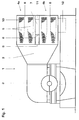
- FIG. 1 shows a steam condenser 1 which is arranged at ground level with respect to a turbine 2 and is connected to it by a condenser neck 3.
- the steam condenser 1 is constructed from two or more identical modules arranged one above the other, two modules 4a, 4b being present in the exemplary embodiment shown.
- the modules 4a, 4b each have two elongated, horizontally oriented tube bundles 5, between which there is a central alley or Damfeinströmgasse.
- the steam space of each module 4a, 4b is enclosed by a steam jacket 6.
- the two modules 4a, 4b are spaced apart from one another by an intermediate space 7, connecting parts 8 being arranged between the two modules and connecting and supporting the middle module walls 9 of the modules 4a, 4b. This connection and support results in a defined stress distribution in these middle module walls 9.
- the water chambers and deflection chambers for the cooling water of each tube bundle are, for example, hemispherical. (You are not in this figure drawn in and described below in connection with FIG. 2.)
- the steam from the turbine 2 flows through the horizontal Condenser neck 3 to the steam condenser 1 and initially flows there into the Middle aisles of the two modules 4a, 4b and from there into the tube bundle 5, where it starts the tubes 10 condensed.
- the condensate in the module 4a accumulates, flows to the bottom of this module and there a condensate drain opening to, which opens into a connecting channel 11. This causes the condensate to get through finally into the module 4b below, where it is together with the there accumulating condensate is collected in Hotwell 12.
- Figure 2 shows the space 7 with the connecting parts 8 and Connection channel 11.
- the connecting parts 8 consist, for example, of several Individual pieces that are distributed across the width of the modules. They serve together with the connection channel 11 of the support of the upper module.
- the connecting parts 8 have openings or eyes 13 for transport purposes which are used in a crane suspension.
- Connecting parts have a double use, that of connection and support during operation and that of the transport and installation aid.
- the space 7 is in the embodiment shown here under atmospheric Print.
- the space is under vacuum, with the Interspace communicates with the steam room of the two modules.
- the connection of the two modules requires additional side walls, which are welded to the side walls of the modules. This variant enables a more direct drainage of the upper module without individual Connecting channels.
- water chambers 14 are with respect to the modules 4a and 4b arranged in this way (the module 4a is not here for better illustration shown) that the semi-cylindrical walls 15 of the water chambers 14th are at the same height as the middle walls 9 of the modules. That means the Jacket 15 of the semi-cylindrical water chambers 14 is in each case with the module 4b connected at the level of the middle module wall 9. This will make the Pressure forces emanating from the water chambers through the middle walls 9 added. In particular, none are created in the middle walls 9 Bending moments, so that no additional bracing ribs or tie rods must be installed to absorb these bending moments.
- FIG 3 shows in section the steam condenser 1 with two modules 4a, 4b are spaced from one another by the intermediate space 7.
- one or more bypass lines 20 are guided, of which in this section one of them can be seen.
- the bypass lines lead from (not shown) Bypassing the turbine bypassing the condenser neck 3 and there a steam introduction device 21.
- this is at the height of the intermediate space 7, that is to say positioned between the two modules 4a and 4b.
- the steam inflow 22 from the turbine 2 into the condenser 1 is through this Positioning of the steam introduction device 21 is not hindered. In the area the cooling pipes therefore do not create any negative eddies or so-called Karman Whirlwinds.
- the steam introduction device has one Steam collecting line 21, that is on its upper and lower side, that is on both sides of the gap 7, a variety of outflow or Has aperture openings 23.
- the bypass steam flow from the bypass lines 20 is relaxed in the manifolds 21 and then passes through the Openings 23 in the condenser neck 3.
- the outflow area 24 of the Bypass steam is indicated by dashed lines. He is compared to conventional steam introducers wider, which helps the inflow speed of the bypass steam is lower and the erosion is increased Components in the capacitor is reduced.
- the middle module walls 9 each have openings 25 which run into the drain of the condensate 26 from the upper module 4a through the connection channel 11 in the lower module 4b serve. From there the condensate gets together with the Finally, condensate from the lower module here into Hotwell 12.
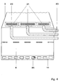
- FIG. 4 shows, in a further section through the intermediate space, the arrangement of three bypass lines 20. All lines lead from the same side of the capacitor through the intermediate space 7 into the condenser neck 3. This arrangement enables the use of shorter and similarly designed and therefore more cost-effective lines. The assembly of lines in this arrangement is also facilitated.
- three steam collecting lines 21 are arranged, which are arranged uniformly distributed over the width of the condenser neck 3.
- Each bypass line 20 leads to an associated steam manifold 21.
- Each manifold 21 has a number of rows of outflow openings 23 over its entire length, through which the bypass steam flows into the condenser neck. In the example shown, these are circular openings.
- the plurality of condensate drain openings 25 are arranged here, for example, over the entire width of the connecting channel 11.
Landscapes
- Engineering & Computer Science (AREA)
- Mechanical Engineering (AREA)
- General Engineering & Computer Science (AREA)
- Heat-Exchange Devices With Radiators And Conduit Assemblies (AREA)
- Details Of Heat-Exchange And Heat-Transfer (AREA)
Abstract
Ein Dampfkondensator (1), der bezüglich einer Dampfturbine (2) ebenerdig angeordnet ist und in den Turbinendampf durch den Kondensatorhals (3) in horizontaler Richtung strömt, weist zwei oder mehr Module (4a, 4b) auf, in denen der Dampf an Kühlrohren (10) kondensiert. Die Module (4a, 4b) sind erfindungsgemäss durch einen definierten Zwischenraum (7) beabstandet. Die mittleren, einander zugewandten Modulwände (9) sind durch Verbindungsteile (8) abgestützt und miteinander verbunden. Dies trägt einer definierten Spannungsverteilung in den mittleren Modulwänden (9) bei. In einer besonderen Ausführung sind in dem Zwischenraum (7) Bypassleitungen (20) angeordnet, die Dampf aus dem Kessel direkt, unter Umgehung der Turbine (2), in den Dampfkondensator (1) führen. Die Bypassleitungen (20) führen hierzu zu einer Dampfeinführungsvorrichtung (21), die auf der Höhe des Zwischenraums (7) am Kondensatorhals (3) angeordnet ist. Durch diese Positionierung ist die Strömung des Turbinendampfes (22) in den Dampfkondensator (1) nicht behindert. <IMAGE>A steam condenser (1), which is arranged at ground level with respect to a steam turbine (2) and flows into the turbine steam through the condenser neck (3) in the horizontal direction, has two or more modules (4a, 4b) in which the steam is passed to cooling pipes ( 10) condensed. According to the invention, the modules (4a, 4b) are spaced apart by a defined intermediate space (7). The middle, mutually facing module walls (9) are supported by connecting parts (8) and connected to each other. This contributes to a defined stress distribution in the middle module walls (9). In a special embodiment, bypass lines (20) are arranged in the intermediate space (7), which lead steam from the boiler directly, bypassing the turbine (2), into the steam condenser (1). For this purpose, the bypass lines (20) lead to a steam introduction device (21), which is arranged at the level of the intermediate space (7) on the condenser neck (3). This positioning does not impede the flow of the turbine steam (22) into the steam condenser (1). <IMAGE>
Description
Die Erfindung betrifft einen Dampfkondensator in einer Dampfkraftanlage oder Kombi-anlage, der mit der Turbine ebenerdig angeordnet ist und zu dem der Turbinendampf durch einen Kondensatorhals in horizontaler Richtung zuströmt. Der Dampfkondensator weist mehrere länglich ausgebildete und horizontal gelagerte Rohrbündel auf, die jeweils durch eine Mittelgasse voneinander beabstandet sind und über die der Dampf in die Rohrbündel strömt. Am Kondensatorhals ist eine Vorrichtung angeordnet für die Einführung von Dampf, der vom Kessel der Kraftanlage über eine Bypassleitung direkt in den Kondensator geleitet wird.The invention relates to a steam condenser in a steam power plant or Combined system, which is arranged at ground level with the turbine and to which the Turbine steam flows in a horizontal direction through a condenser neck. The steam condenser has several elongated and horizontal stored tube bundles, each separated by a central aisle are spaced and through which the steam flows into the tube bundle. At the Condenser neck is a device arranged for the introduction of steam, from the boiler of the power plant via a bypass line directly into the Condenser is passed.
Ein solcher Dampfkondensator mit horizontaler Dampfzuströmung ist zum Beispiel
in der EP 0 384 200 beschrieben. Er weist mehrere länglich ausgebildete und
horizontal angeordnete Bündel von Rohren auf, durch die das Kühlwasser fliesst.
Die Dampfzuströmung aus der Turbine erfolgt in horizontaler Richtung über den
Kondensatorhals in die Mittelgassen und von dort in das Innere der Rohrbündel,
wo der Dampf kondensiert. Das an den Rohren sich bildende Kondensat fliesst
über Kondensatsammelbleche hinab in ein Hotwell im Bereich des Bodens des
Kondensators.
In der Praxis ist ein solcher Dampfkondensator modular aufgebaut, wobei jedes
Modul beispielsweise zwei Rohrbündel enthält, zwischen denen ein freier Raum
oder eine Mittelgasse besteht, durch die der Dampf zu den Kühlrohren in den
Rohrbündeln gelangen kann. Die Module sind aus Platzgründen jeweils
übereinander liegend angeordnet, wobei ihre mittleren, horizontalen Modulwände,
welche einem benachbarten Modul zugewandt sind, durch
Montageschweissnähte miteinander verbunden sind. Das Kondensat, das in den
Rohrbündeln des oberen Moduls anfällt, fliesst einer Öffnung am Boden jenes
Moduls zu. Von dort gelangt es schliesslich in das untere Modul und in das
Hotwell des Kondensators.
Die Schweissverbindung zwischen den mittleren Modulwänden birgt das Risiko,
dass aufgrund von Fabrikationstoleranzen ein Spalt entlang dieser Modulwände
entstehen kann. Dadurch sind dort die Kontaktflächen unregelmässig, und es
ergeben sich ungleichmässige Spannungen. Diese können, insbesondere im
Bereich der Abflussöffnung für das Kondensat vom oberen in das untere Modul,
zu Undichtheiten führen und ein Korrosionsrisiko hervorrufen. Da die Modulwände
direkt aufeinander liegen, kann diese Korrosion visuell nicht inspiziert werden und
nötigenfalls eine Reparatur veranlasst werden.Such a steam condenser with horizontal steam inflow is described for example in
In practice, such a steam condenser is of modular construction, with each module containing, for example, two tube bundles, between which there is a free space or a central lane through which the steam can reach the cooling tubes in the tube bundles. For reasons of space, the modules are arranged one above the other, their central, horizontal module walls, which face an adjacent module, being connected to one another by assembly weld seams. The condensate that accumulates in the tube bundles of the upper module flows to an opening at the bottom of that module. From there it finally gets into the lower module and into the hotwell of the capacitor.
The welded connection between the middle module walls bears the risk that a gap can occur along these module walls due to manufacturing tolerances. As a result, the contact areas there are irregular and there are uneven tensions. These can lead to leaks and create a risk of corrosion, especially in the area of the drain opening for the condensate from the upper to the lower module. Since the module walls lie directly on top of each other, this corrosion cannot be inspected visually and a repair can be arranged if necessary.
Beim An- und Abfahren einer Kraftanlage sowie beim Lastabwurf wird zwecks
Betriebssicherheit und Reduzierung von Verlusten Dampf aus dem Kessel über
eine Dampfumleitstation direkt dem Kondensator zugeführt. Eine solche
Umleitstation besteht typischerweise aus zwei bis drei Bypassleitungen, welche
die Turbine umgehen, und einer Dampfeinführungsvorrichtung im
Kondensatorhals. Die Massenströme durch die Umleitstation sind oft grösser als
der Turbinendampfstrom während des normalen Turbinenbetriebs, dies
insbesondere bei Kombi-anlagen. Da die Querschnitte der Bypassleitungen um
vieles kleiner sind als der Querschnitt des Turbinenabdampfstutzens, ergeben
sich in den Bypassleitungen sehr stark konzentrierte Dampfströme. In der
Dampfeinführungsvorrichtung strömt der Dampf in einigen Fällen zudem bei
Überschallgeschwindigkeit, was zu Erosionsschäden an Bauteilen im
Kondensator führen kann.
Die Platzverhältnisse am Kondensatorhals sind zum Teil eingeschränkt, da
weitere Anlagen ebenfalls dort platziert sein müssen. Die Rohrleitungsplanung für
die Bypassleitungen ist deshalb umständlich, und die Platzierung der
Einführungsvorrichtung am Kondensatorhals ist bezüglich der Strömungsdynamik
schwer zu optimieren.When starting up and shutting down a power plant and when shedding loads, steam from the boiler is fed directly to the condenser via a steam bypass station for operational safety and to reduce losses. Such a diversion station typically consists of two to three bypass lines that bypass the turbine and a steam introduction device in the condenser neck. The mass flows through the diversion station are often greater than the turbine steam flow during normal turbine operation, especially in combination systems. Since the cross-sections of the bypass lines are much smaller than the cross-section of the turbine evaporation nozzle, there are very highly concentrated steam flows in the bypass lines. In some cases, the steam in the steam introduction device also flows at supersonic speeds, which can lead to erosion damage to components in the condenser.
The space available at the condenser neck is partially restricted, since other systems must also be placed there. The pipeline planning for the bypass lines is therefore cumbersome, and the placement of the insertion device on the condenser neck is difficult to optimize with regard to the flow dynamics.
In Anbetracht des hier beschriebenen Standes der Technik ist es die Aufgabe der Erfindung, einen modular aufgebauten Dampfkondensator der eingangs beschriebenen Art zu schaffen, der die erwähnten Nachteile der Verbindung der Module vermeidet.In view of the prior art described here, it is the task of Invention, a modular steam condenser of the beginning described type to create, which mentioned the disadvantages of connecting the Avoids modules.
Diese Aufgabe ist durch einen Dampfkondensator gemäss Anspruch 1 gelöst.
Die übereinander angeordneten Module des Dampfkondensators sind
erfindungsgemäss voneinander beabstandet, indem zwischen den benachbarten
Modulen ein definierter Zwischenraum besteht, wobei zwischen den Wänden der
beiden Module, die einander zugewandt sind mehrere Verbindungsteile
angeordnet sind.This object is achieved by a steam condenser according to
Durch die Beabstandung der Module mittels eines definierten Zwischenraums werden die eingangs erwähnten Spaltflächen und die damit verbundenen Risiken von Korrosion und Spannungen in den Modulwänden vermieden. Der Zwischenraum ist zweckmässigerweise so dimensioniert, dass ein Zugang für Montagearbeiten und eine visuelle Inspektion des Bereichs der Modulwände ermöglicht sind. Schliesslich erbringt die Beabstandung der Module eine Fabrikationserleichterung, indem beide oder alle Module identisch hergestellt und durch die Verbindungsteile miteinander verbunden werden können. Dabei sind auch die Anzahl notwendiger Schweissnähte erheblich reduziert.By spacing the modules by means of a defined space the gap areas mentioned above and the associated risks of corrosion and tension in the module walls avoided. The Intermediate space is expediently dimensioned such that access for Assembly work and a visual inspection of the area of the module walls are possible. Finally, the spacing of the modules provides one Facilitation of manufacture by manufacturing both or all modules identically and can be connected to each other by the connecting parts. Are there the number of necessary welds is also considerably reduced.
Die Verbindungsteile dienen sowohl der Definition des Raumes zwischen den Modulen als auch der Abstützung der Module und erbringen dadurch den Vorteil, dass die Spannungsverteilung in den mittleren Modulwänden gleichsam definiert ist. Die Spannungen werden nun auch nicht mehr von den Fabrikationstoleranzen beeinflusst.The connecting parts serve both to define the space between the Modules as well as the support of the modules and thereby provide the advantage that the stress distribution in the middle module walls is defined as it were is. The tensions are no longer affected by the manufacturing tolerances influenced.
Die benachbarten Module sind ferner jeweils durch einen Verbindungskanal verbunden zwecks der Abführung des Kondensats, das in einem oben angeordneten Modul anfällt durch eine Kondensatabflussöffnung im Boden jenes Moduls in das unten liegende Modul fliesst.The neighboring modules are also each through a connection channel connected in order to drain the condensate, which is in a top arranged module occurs through a condensate drain opening in the bottom of that Module flows into the module below.
In einem ersten Ausführungsbeispiel ist der Raum zwischen den Modulen unter atmosphärischem Druck. In einem alternativen Ausführungsbeispiel ist der Zwischenraum durch Seitenwände umschlossen und steht in Verbindung mit dem Dampfraum unter Vakuum. Die erste Ausführung des Zwischenraums unter Atmosphärendruck hat vergleichsweise den Vorteil, dass die Abstützung der Module weniger Bauteile erfordert und deshalb einfacher realisierbar ist. Die zweite Ausführung hat hingegen den Vorteil, dass sie eine einfachere Entwässerung des oberen Moduls ohne mehrere einzelne Verbindungskanäle ermöglicht.In a first embodiment, the space between the modules is below atmospheric pressure. In an alternative embodiment, the The space is enclosed by side walls and is connected to the Steam room under vacuum. The first execution of the space below Atmospheric pressure has the comparative advantage that the support of the Modules requires fewer components and is therefore easier to implement. The second version, on the other hand, has the advantage of being a simpler one Drainage of the upper module without several individual connection channels enables.
In einer bevorzugten Ausführung der Erfindung sind die mittleren, horizontal liegenden und einander zugewandten Modulwände auf der Höhe angeordnet, sodass sie auf gleicher Höhe mit den zylindrischen Wänden der Wasserkammern liegen. Diese Anordnung trägt der Übernahme der Druckkräfte aus den Wasserkammern vorteilhaft bei. Es werden dadurch Biegemomente vermieden, die sonst aus dem Druck aus den Wasserkammern auf die mittleren Modulwände entstehen. Zuganker oder Verspannungsrippen, die sonst für die Aufnahme solcher Biegemomente notwendig sind, sind nicht mehr erforderlich, wodurch Fabrikations- und Montagekosten eingespart werden.In a preferred embodiment of the invention, the middle ones are horizontal lying and facing module walls arranged at the height, so that they are level with the cylindrical walls of the water chambers lie. This arrangement carries the pressure forces from the Water chambers advantageous at. This prevents bending moments which otherwise from the pressure from the water chambers on the middle module walls arise. Tie rods or bracing ribs that are otherwise used for the intake such bending moments are no longer required, so Manufacturing and assembly costs can be saved.
In einem weiteren Ausführungsbeispiel der Erfindung weisen die Verbindungsteile oder Laschen Öffnungen auf, die als Transportaufhängevorrichtungen verwendet werden können. In a further embodiment of the invention, the connecting parts or tabs on openings used as transport hangers can be.
In einer weiteren besonderen Ausführung wird der Zwischenraum zur Platzierung von Bypassleitungen verwendet. Vorzugsweise werden alle Bypassleitungen von derselben Seite des Kondensators in den Zwischenraum und von dort zu einer Dampfeinführungsvorrichtung am Kondensatorhals geführt. Der Zwischenraum ermöglicht hierdurch eine stark vereinfachte Leitungsanordnung, wodurch die Leitungen kürzer sind und in allen Leitungen ähnliche Strömungsverhältnisse vorherrschen.In another special version, the space is used for placement used by bypass lines. Preferably, all bypass lines from same side of the capacitor in the space and from there to one Steam introduction device guided on the condenser neck. The gap thereby enables a greatly simplified line arrangement, whereby the Lines are shorter and similar flow conditions in all lines prevalence.
Die Dampfeinführungsvorrichtung ist auf der Höhe des Zwischenraumes
angeordnet. Dies hat den Vorteil, dass die Dampfeinführungsvorrichtung die
Turbinendampfströmung in den Kondensator nicht behindert, da sie bezüglich
dieser Dampfströmung in einer "toten" Zone liegt.
Die Dampfeinführungsvorrichtung weist eine perforierte Bypasssammelleitung mit
mehreren Rohrstücken auf, die sich über die gesamte Breite des
Kondensatorhalses erstreckt. Zu jedem dieser Rohrstücke führt eine
Bypassleitung. Jedes Rohrstück weist als Perforierung mehrere Reihen von
Öffnungen oder Blendenbohrungen, durch die der Bypassdampf in den
Kondensatorhals tritt.The steam introduction device is arranged at the level of the gap. This has the advantage that the steam introduction device does not hinder the flow of turbine steam into the condenser, since it lies in a "dead" zone with respect to this steam flow.
The steam introduction device has a perforated bypass manifold with a plurality of pipe pieces, which extends over the entire width of the condenser neck. A bypass line leads to each of these pipe sections. Each piece of pipe has several rows of openings or apertures through which the bypass steam enters the condenser neck.
Die perforierte Bypasssammelleitung ist einerseits in der gleichen Richtung wie die Kühlwasserrohre des Kondensators, anderseits auf der Höhe des Zwischenraumes angeordnet, wo sich keine Kühlrohre befinden. Hinter ihr befindet sich also lediglich der Zwischenraum, sodass dort keine negativen Wirbel entstehen, welche die Turbinendampfströmung zu den Kühlrohren behindern würde.The perforated bypass manifold is on the one hand in the same direction as the cooling water pipes of the condenser, on the other hand at the level of the Intermediate space where there are no cooling tubes. Behind her So there is only the gap, so there are no negative eddies arise, which impede the turbine steam flow to the cooling tubes would.
Die mehrreihigen Blendenbohrungen über die gesamte Länge der Bypasssammelleitung und so über die gesamte Breite des Kondensatorhalses erbringt ferner den Vorteil, dass der Bypassdampf so entspannt ist, dass das Risiko durch Erosion an Bauteilen im Kondensator und Kondensatorhals durch den Bypassdampf reduziert ist. The multi-row aperture holes over the entire length of the Bypass manifold and so over the entire width of the condenser neck also has the advantage that the bypass steam is so relaxed that the Risk of erosion on components in the condenser and condenser neck the bypass steam is reduced.
Es zeigen:
Figur 1 zeigt einen Dampfkondensator 1, der bezüglich einer Turbine 2 ebenerdig
angeordnet ist und mit ihr durch einen Kondensatorhals 3 verbunden ist. Der
Dampfkondensator 1 ist aus zwei oder mehr identischen, übereinander
angeordneten Modulen aufgebaut, wobei im gezeigten Ausführungsbeispiel zwei
Module 4a, 4b vorhanden sind. Die Module 4a, 4b weisenje zwei länglich
ausgebildete, horizontal ausgerichtete Rohrbündel 5 auf, zwischen denen sich
eine Mittelgasse oder Damfeinströmgasse befindet. Der Dampfraum jedes Moduls
4a, 4b ist von einem Dampfmantel 6 umschlossen. Die beiden Module 4a, 4b sind
durch einen Zwischenraum 7 voneinander beabstandet, wobei zwischen den
beiden Modulen Verbindungsteile 8 angeordnet sind, welche die mittleren
Modulwände 9 der Module 4a, 4b miteinander verbinden und abstützen.
Durch diese Verbindung und Abstützung ergibt sich in diesen mittleren
Modulwänden 9 eine definierte Spannungsverteilung. FIG. 1 shows a
This connection and support results in a defined stress distribution in these
Die Wasserkammern und Umlenkkammern für das Kühlwasser jedes Rohrbündels sind beispielsweise halbkugelförmig ausgebildet. (Sie sind in dieser Figur nicht eingezeichnet und nachfolgend in Zusammenhang mit der Figur 2 beschrieben.)The water chambers and deflection chambers for the cooling water of each tube bundle are, for example, hemispherical. (You are not in this figure drawn in and described below in connection with FIG. 2.)
Der Dampf aus der Turbine 2 strömt in horizontaler Richtung durch den
Kondensatorhals 3 dem Dampfkondensator 1 zu und strömt dort zunächst in die
Mittelgassen der beiden Module 4a, 4b und von dort in die Rohrbündel 5, wo er an
den Rohren 10 kondensiert. Das Kondensat, das im oben angeordneten Modul 4a
anfällt, fliesst zum Boden dieses Moduls und dort einer Kondensatabflussöffnung
zu, die in einen Verbindungskanal 11 mündet. Hierdurch gelangt das Kondensat
schliesslich in das unten angeordnete Modul 4b, wo es zusammen mit dem dort
anfallenden Kondensat im Hotwell 12 angesammelt wird.The steam from the
Figur 2 zeigt den Zwischenraum 7 mit den Verbindungsteilen 8 und dem
Verbindungskanal 11. (Zwecks besserer Ansicht ist das obere Modul nicht
eingezeichnet.) Die Verbindungsteile 8 bestehen beispielsweise aus mehreren
Einzelstücken, die über die Breite der Module verteilt sind. Sie dienen zusammen
mit dem Verbindungskanal 11 der Abstützung des oberen Moduls.Figure 2 shows the
Zu Transportzwecken weisen die Verbindungsteile 8 Öffnungen oder Augen 13
auf, welche bei einer Kranaufhängung angewendet werden. Dadurch haben die
Verbindungsteile eine doppelte Verwendung, die der Verbindung und Abstützung
während des Betriebs sowie die der Transport- und Installationshilfe.The connecting
Der Zwischenraum 7 ist in der hier gezeigten Ausführung unter atmosphärischem
Druck. In einer Variante ist der Zwischenraum unter Vakuum, wobei der
Zwischenraum mit dem Dampfraum der beiden Module in Verbindung steht.
Hierzu erfordert die Verbindung der beiden Module zusätzliche Seitenwände,
welche mit den Seitenwänden der Module verschweisst sind. Diese Variante
ermöglicht eine direktere Entwässerung des oberen Moduls ohne einzelne
Verbindungskanäle. The
In der hier gezeigten Ausführung sind Wasserkammern 14 bezüglich der Module
4a und 4b so angeordnet (das Modul 4a ist hier zwecks besserer Darstellung nicht
eingezeichnet), dass die halb-zylindrischen Wände 15 der Wasserkammern 14
auf gleicher Höhe liegen wie die mittleren Wände 9 der Module. Das heisst der
Mantel 15 der halb-zylindrischen Wasserkammern 14 ist jeweils mit dem Modul 4b
auf der Höhe der mittleren Modulwand 9 verbunden. Hierdurch werden die
Druckkräfte, die von den Wasserkammern ausgehen durch die Mittelwände 9
aufgenommen. Es entstehen insbesondere in den Mittelwänden 9 keine
Biegemomente, sodass keine zusätzlichen Verspannungsrippen oder Zuganker
eingebaut werden müssen, um diese Biegemomente aufzunehmen.In the embodiment shown here,
Figur 3 zeigt im Schnitt den Dampfkondensator 1 mit zwei Modulen 4a, 4b, die
durch den Zwischenraum 7 voneinander beabstandet sind. In dem Zwischenraum
7 sind eine oder mehrere Bypassleitungen 20 geführt, wovon in diesem Schnitt
eine davon ersichtlich ist. Die Bypassleitungen führen vom (nicht dargestellten)
Kessel unter Umgehung der Turbine direkt in den Kondensatorhals 3 und dort zu
einer Dampfeinführungsvorrichtung 21. Diese ist erfindungsgemäss auf der Höhe
des Zwischenraums 7, also zwischen den beiden Modulen 4a und 4b positioniert.
Die Dampfzuströmung 22 aus der Turbine 2 in den Kondensator 1 ist durch diese
Positionierung der Dampfeinführungsvorrichtung 21 nicht behindert. Im Bereich
der Kühlrohre entstehen daher keine negativen Wirbel oder sogenannte Karman
Wirbelschleppen. Die Dampfeinführungsvorrichtung weist eine
Dampfsammelleitung 21 auf, die an ihrer oberen und unteren Seite, das heisst
beidseits des Zwischenraums 7, eine Vielzahl von Ausström- oder
Blendenöffnungen 23 aufweist. Der Bypassdampfstrom aus den Bypassleitungen
20 wird in den Sammelleitungen 21 entspannt und tritt sodann durch die
Öffnungen 23 in den Kondensatorhals 3. Der Ausströmbereich 24 des
Bypassdampfes ist mit gestrichelten Linien angedeutet. Er ist im Vergleich zu
herkömmlichen Dampfeinführungsvorrichtungen breiter, was dazu beiträgt, dass
die Einströmgeschwindigkeit des Bypassdampfes geringer und die Erosion an
Bauteilen im Kondensator reduziert ist. Figure 3 shows in section the
Die mittleren Modulwände 9 weisen jeweils Öffnungen 25 auf, die dem Abfluss
des Kondensats 26 aus dem oberen Modul 4a durch den Verbindungskanal 11 in
das untere Modul 4b dienen. Von dort gelangt das Kondensat zusammen mit dem
Kondensat aus dem unteren Modul schliesslich hier in das Hotwell 12.The
Figur 4 zeigt in einem weiteren Schnitt durch den Zwischenraum die Anordnung
von drei Bypassleitungen 20. Sämtliche Leitungen führen von der gleichen Seite
des Kondensators durch den Zwischenraum 7 in den Kondensatorhals 3. Diese
Anordnung ermöglicht den Einsatz von kürzeren sowie ähnlich gestalteten und
deshalb kostengünstigeren Leitungen. Zudem ist die Montage von Leitungen in
dieser Anordnung erleichtert.
Im Kondensatorhals 3 sind drei Dampfsammelleitungen 21 angeordnet, die über
die Breite des Kondensatorhalses 3 gleichmässig verteilt angeordnet sind. Jede
Bypassleitung 20 führt zu einer ihr zugehörigen Dampfsammelleitung 21. Jede
Sammelleitung 21 weist über ihre gesamte Länge mehrere Reihen von
Ausströmöffnungen 23 auf, durch die der Bypassdampf in den Kondensatorhals
strömt. In dem gezeigten Beispiel sind diese kreisrunde Öffnungen.
Die mehreren Kondensatabflussöffnungen 25 sind hier beispielsweise über die
gesamte Breite Verbindungskanals 11 angeordnet. FIG. 4 shows, in a further section through the intermediate space, the arrangement of three
In the
The plurality of
- 11
- DampfkondensatorSteam condenser
- 22nd
- DampfturbineSteam turbine
- 33rd
- KondensatorhalsCondenser neck
- 4a4a
- erstes Modulfirst module
- 4b4b
- zweites Modulsecond module
- 55
- RohrbündelTube bundle
- 66
- DampfmantelSteam jacket
- 77
- ZwischenraumSpace
- 88th
- VerbindungsteileConnecting parts
- 99
- Mittlere ModulwändeMedium module walls
- 1010th
- RohreTube
- 1111
- VerbindungskanalConnecting channel
- 1212th
- HotwellHotwell
- 1313
- Öffnungen, AugenOpenings, eyes
- 1414
- WasserkammernWater chambers
- 1515
- Seitenwände der WasserkammernSidewalls of the water chambers
- 2020th
- BypassleitungBypass line
- 2121
- DampfsammelleitungSteam manifold
- 2222
- Dampfzuströmung aus der TurbineSteam inflow from the turbine
- 2323
- Ausströmöffnungen, BlendenöffnungenOutflow openings, aperture openings
- 2424th
- Ausströmbereich des BypassdampfesOutflow area of the bypass steam
- 2525th
- KondensatabflussöffnungCondensate drain opening
- 2626
- KondensatflussCondensate flow
Claims (9)
dadurch gekennzeichnet, dass
die zwei oder mehreren Module (4a, 4b) jeweils durch einen definierten Zwischenraum (7) voneinander beabstandet sind und in dem Zwischenraum (7) oder den Zwischenräumen (7) jeweils Verbindungsteile (8) angeordnet sind, welche die einander benachbarten Module (4a, 4b) abstützen.Steam condenser (1) which is arranged at ground level with respect to a steam turbine (2) and to which the turbine steam flows in a horizontal direction through a condenser neck (3) and which has two or more modules (4a, 4b) which are arranged one above the other and each of them are enclosed in a steam jacket (6) and in the steam rooms each contain tube bundles (5) with cooling tubes (10) through which cooling water flows from water chambers (14),
characterized in that
the two or more modules (4a, 4b) are each spaced apart from one another by a defined intermediate space (7) and in the intermediate space (7) or the intermediate spaces (7) there are in each case connecting parts (8) which separate the adjacent modules (4a, 4b) support.
dadurch gekennzeichnet, dass
zwischen den benachbarten Modulen (4a, 4b) jeweils ein Verbindungskanal (11) angeordnet ist, in den Kondensat, das im oben angeordneten Modul (4a) anfällt über Kondensatabflussöffnungen (25) fliesst und von dort über eine Öffnung (25) in das unten angeordnete Modul (4b) gelangt.Steam condenser (1) according to claim 1,
characterized in that
Between the adjacent modules (4a, 4b) a connection channel (11) is arranged, into which condensate, which accumulates in the module (4a) arranged above, flows through condensate drain openings (25) and from there via an opening (25) into the one below Module (4b) arrives.
dadurch gekennzeichnet, dass
der Zwischenraum (7) zwischen zwei benachbarten Modulen (4a, 4b) jeweils unter atmosphärischem Druck steht. Steam condenser (1) according to claim 2,
characterized in that
the space (7) between two adjacent modules (4a, 4b) is under atmospheric pressure.
dadurch gekennzeichnet, dass
der Zwischenraum (7) zwischen zwei benachbarten Modulen (4a, 4b) jeweils Seitenwände aufweist und der Zwischenraum (7) durch die Seitenwände, den Verbindungskanal (11) und eine Wand am Ende des Kondensatorhalses (3) umschlossen ist, und der Zwischenraum (7) in Verbindung mit den Dampfräumen der Module (4a, 4b) ist und unter Vakuum steht.Steam condenser (1) according to claim 2,
characterized in that
the space (7) between two adjacent modules (4a, 4b) each has side walls and the space (7) is enclosed by the side walls, the connecting channel (11) and a wall at the end of the condenser neck (3), and the space (7 ) in connection with the steam rooms of the modules (4a, 4b) and is under vacuum.
dadurch gekennzeichnet, dass
die halb-zylindrischen Wände (15) der Wasserkammern (14) mit den Modulen (4a, 4b) auf der Höhe der mittleren, einander zugewandten Wände (9) der Module (4a, 4b) verbunden sind.Steam condenser (1) according to claim 3 or 4,
characterized in that
the semi-cylindrical walls (15) of the water chambers (14) are connected to the modules (4a, 4b) at the level of the middle, facing walls (9) of the modules (4a, 4b).
dadurch gekennzeichnet, dass
eine oder mehrere Bypassleitungen (20) im Zwischenraum (7) angeordnet sind und zu einer Dampfeinführungsvorrichtung (21) führen, die am Kondensatorhals (3) auf der Höhe des Zwischenraums (7) angeordnet ist.Steam condenser (1) according to one of claims 3 to 5,
characterized in that
one or more bypass lines (20) are arranged in the intermediate space (7) and lead to a steam introduction device (21) which is arranged on the condenser neck (3) at the level of the intermediate space (7).
dadurch gekennzeichnet, dass
die Dampfeinführungsvorrichtung (21) eine Sammelleitung (21) für jede Bypassleitung (20) aufweist, die über die Breite des Kondensatorhalses (3) verteilt angeordnet sind. Steam condenser (1) according to claim 6,
characterized in that
the steam introduction device (21) has a collecting line (21) for each bypass line (20), which are arranged distributed over the width of the condenser neck (3).
dadurch gekennzeichnet, dass
die Dampfeinführungsvorrichtung (21) Ausströmöffnungen (23) aufweist, durch die der Bypassdampf in den Kondensatorhals (3) strömt.Steam condenser (1) according to claim 6 or 7,
characterized in that
the steam introduction device (21) has outflow openings (23) through which the bypass steam flows into the condenser neck (3).
dadurch gekennzeichnet, dass
die Ausströmöffnungen (23) rund ausgebildet sind.Steam condenser (1) according to claim 8,
characterized in that
the outflow openings (23) are round.
Priority Applications (4)
| Application Number | Priority Date | Filing Date | Title |
|---|---|---|---|
| EP00810112A EP1126227A1 (en) | 2000-02-09 | 2000-02-09 | Steam condenser |
| CA002334559A CA2334559A1 (en) | 2000-02-09 | 2001-02-06 | Steam condenser |
| HU0100633A HUP0100633A2 (en) | 2000-02-09 | 2001-02-08 | Steam condenser |
| US09/779,663 US6360543B2 (en) | 2000-02-09 | 2001-02-09 | Steam condenser |
Applications Claiming Priority (1)
| Application Number | Priority Date | Filing Date | Title |
|---|---|---|---|
| EP00810112A EP1126227A1 (en) | 2000-02-09 | 2000-02-09 | Steam condenser |
Publications (1)
| Publication Number | Publication Date |
|---|---|
| EP1126227A1 true EP1126227A1 (en) | 2001-08-22 |
Family
ID=8174545
Family Applications (1)
| Application Number | Title | Priority Date | Filing Date |
|---|---|---|---|
| EP00810112A Withdrawn EP1126227A1 (en) | 2000-02-09 | 2000-02-09 | Steam condenser |
Country Status (4)
| Country | Link |
|---|---|
| US (1) | US6360543B2 (en) |
| EP (1) | EP1126227A1 (en) |
| CA (1) | CA2334559A1 (en) |
| HU (1) | HUP0100633A2 (en) |
Families Citing this family (7)
| Publication number | Priority date | Publication date | Assignee | Title |
|---|---|---|---|---|
| US7124580B2 (en) | 2004-06-22 | 2006-10-24 | Crown Iron Works Company | Sub-zero condensation vacuum system |
| US8286430B2 (en) * | 2009-05-28 | 2012-10-16 | General Electric Company | Steam turbine two flow low pressure configuration |
| US8813500B2 (en) * | 2011-08-03 | 2014-08-26 | Dresser-Rand Company | Combined heat exchanger expander mounting system |
| JP6221168B2 (en) * | 2013-03-27 | 2017-11-01 | 三菱日立パワーシステムズ株式会社 | Condenser and steam turbine plant equipped with the same |
| CN105793659B (en) * | 2014-01-23 | 2018-05-01 | 三菱日立电力系统株式会社 | Condenser |
| WO2017145404A1 (en) * | 2016-02-25 | 2017-08-31 | 三菱日立パワーシステムズ株式会社 | Condenser and steam turbine plant provided with same |
| CN113295019A (en) * | 2021-05-11 | 2021-08-24 | 于都县正亿纸品纸业有限公司 | Steam recovery device |
Citations (7)
| Publication number | Priority date | Publication date | Assignee | Title |
|---|---|---|---|---|
| CH414682A (en) * | 1962-08-23 | 1966-06-15 | Ass Elect Ind | Steam turbine plant |
| US4253516A (en) * | 1978-06-22 | 1981-03-03 | Westinghouse Electric Corp. | Modular heat exchanger |
| EP0128452A1 (en) * | 1983-06-03 | 1984-12-19 | Delas-Weir | Modular tube bundle for a vapour condenser, and vapour condenser using such a bundle |
| EP0384200A1 (en) | 1989-02-23 | 1990-08-29 | Asea Brown Boveri Ag | Steam condenser |
| EP0594499A1 (en) * | 1992-10-21 | 1994-04-27 | Gec Alsthom Electromecanique Sa | Condenser made of concrete for turbine with axial outlet with simplified mounting of the bundles |
| WO1998015720A1 (en) * | 1996-10-08 | 1998-04-16 | Siemens Aktiengesellschaft | Steam turbine system |
| EP0957325A1 (en) * | 1998-05-14 | 1999-11-17 | Asea Brown Boveri AG | Steam condenser |
Family Cites Families (4)
| Publication number | Priority date | Publication date | Assignee | Title |
|---|---|---|---|---|
| DE2107013A1 (en) * | 1971-02-13 | 1972-08-17 | Kraftwerk Union Ag | Condensation system for the exhaust steam from steam power plants |
| US3881548A (en) * | 1971-07-14 | 1975-05-06 | Westinghouse Electric Corp | Multi-temperature circulating water system for a steam turbine |
| US4059959A (en) * | 1976-11-05 | 1977-11-29 | Sperry Rand Corporation | Geothermal energy processing system with improved heat rejection |
| US4747360A (en) * | 1983-06-24 | 1988-05-31 | General Electric Company | Condenser integrated turbine support |
-
2000
- 2000-02-09 EP EP00810112A patent/EP1126227A1/en not_active Withdrawn
-
2001
- 2001-02-06 CA CA002334559A patent/CA2334559A1/en not_active Abandoned
- 2001-02-08 HU HU0100633A patent/HUP0100633A2/en unknown
- 2001-02-09 US US09/779,663 patent/US6360543B2/en not_active Expired - Fee Related
Patent Citations (7)
| Publication number | Priority date | Publication date | Assignee | Title |
|---|---|---|---|---|
| CH414682A (en) * | 1962-08-23 | 1966-06-15 | Ass Elect Ind | Steam turbine plant |
| US4253516A (en) * | 1978-06-22 | 1981-03-03 | Westinghouse Electric Corp. | Modular heat exchanger |
| EP0128452A1 (en) * | 1983-06-03 | 1984-12-19 | Delas-Weir | Modular tube bundle for a vapour condenser, and vapour condenser using such a bundle |
| EP0384200A1 (en) | 1989-02-23 | 1990-08-29 | Asea Brown Boveri Ag | Steam condenser |
| EP0594499A1 (en) * | 1992-10-21 | 1994-04-27 | Gec Alsthom Electromecanique Sa | Condenser made of concrete for turbine with axial outlet with simplified mounting of the bundles |
| WO1998015720A1 (en) * | 1996-10-08 | 1998-04-16 | Siemens Aktiengesellschaft | Steam turbine system |
| EP0957325A1 (en) * | 1998-05-14 | 1999-11-17 | Asea Brown Boveri AG | Steam condenser |
Also Published As
| Publication number | Publication date |
|---|---|
| CA2334559A1 (en) | 2001-08-09 |
| HUP0100633A2 (en) | 2002-07-29 |
| HU0100633D0 (en) | 2001-04-28 |
| US6360543B2 (en) | 2002-03-26 |
| US20010011458A1 (en) | 2001-08-09 |
Similar Documents
| Publication | Publication Date | Title |
|---|---|---|
| EP1642075B1 (en) | Exhaust steam line for steam plants | |
| EP3201550B1 (en) | Installation for condensing steam | |
| DE60103389T2 (en) | A HEAT EXCHANGE | |
| WO2006021315A1 (en) | Rolled heat exchanger | |
| DE102018101344A1 (en) | Cooling unit, plant and process | |
| WO2009152830A1 (en) | Conversion set for a tube bundle heat exchanger | |
| DE1601127B2 (en) | Cooling system with a cooling tower working with natural draft | |
| DE1501618C3 (en) | Heat exchanger | |
| DE202014104666U1 (en) | Plant for the condensation of steam | |
| EP1126227A1 (en) | Steam condenser | |
| EP0069262A1 (en) | Apparatus by which heat is transmitted through hollow fibres | |
| DE1932027A1 (en) | Heat exchanger | |
| DE19642100B4 (en) | steam condenser | |
| EP0619466A2 (en) | Steam condenser | |
| DE2821382A1 (en) | PLATE HEAT EXCHANGER | |
| DE10033691A1 (en) | Condenser neck used to feed steam from steam turbine to condenser has two level cover plates and two side walls that widen in flow direction of steam and have favorable shape with respect to flow technology | |
| EP3134676B1 (en) | Heat exchanger | |
| DE1939245C3 (en) | Air-cooled condenser for the top product of a distilling or rectifying column | |
| DE1942433C3 (en) | Fuel assembly for nuclear reactors | |
| DE2711545C2 (en) | Heat exchangers with a large number of straight tube bundles | |
| DE2158920A1 (en) | Device for steam drying and overheating | |
| DE1451270C3 (en) | Heat exchanger of a nuclear reactor plant | |
| DE2541200A1 (en) | FUEL ELEMENT FOR LIGHT OR HEAVY WATER COOLED NUCLEAR REACTORS | |
| DE1514501B2 (en) | Nuclear reactor plant with steam generator | |
| DE10211179C1 (en) | Spacer for the fuel element of a boiling water reactor |
Legal Events
| Date | Code | Title | Description |
|---|---|---|---|
| PUAI | Public reference made under article 153(3) epc to a published international application that has entered the european phase |
Free format text: ORIGINAL CODE: 0009012 |
|
| AK | Designated contracting states |
Kind code of ref document: A1 Designated state(s): AT BE CH CY DE DK ES FI FR GB GR IE IT LI LU MC NL PT SE |
|
| AX | Request for extension of the european patent |
Free format text: AL;LT;LV;MK;RO;SI |
|
| RAP1 | Party data changed (applicant data changed or rights of an application transferred) |
Owner name: ALSTOM (SWITZERLAND) LTD |
|
| 17P | Request for examination filed |
Effective date: 20020118 |
|
| RAP1 | Party data changed (applicant data changed or rights of an application transferred) |
Owner name: ALSTOM (SWITZERLAND) LTD |
|
| AKX | Designation fees paid |
Free format text: DE ES FR GB IT |
|
| STAA | Information on the status of an ep patent application or granted ep patent |
Free format text: STATUS: THE APPLICATION HAS BEEN WITHDRAWN |
|
| 18W | Application withdrawn |
Effective date: 20030613 |