EP1125829A2 - Vehicle structure with load transmission elements - Google Patents
Vehicle structure with load transmission elements Download PDFInfo
- Publication number
- EP1125829A2 EP1125829A2 EP00308308A EP00308308A EP1125829A2 EP 1125829 A2 EP1125829 A2 EP 1125829A2 EP 00308308 A EP00308308 A EP 00308308A EP 00308308 A EP00308308 A EP 00308308A EP 1125829 A2 EP1125829 A2 EP 1125829A2
- Authority
- EP
- European Patent Office
- Prior art keywords
- cross member
- floor
- vehicle
- extending
- load
- Prior art date
- Legal status (The legal status is an assumption and is not a legal conclusion. Google has not performed a legal analysis and makes no representation as to the accuracy of the status listed.)
- Granted
Links
Images


Classifications
-
- B—PERFORMING OPERATIONS; TRANSPORTING
- B62—LAND VEHICLES FOR TRAVELLING OTHERWISE THAN ON RAILS
- B62D—MOTOR VEHICLES; TRAILERS
- B62D25/00—Superstructure or monocoque structure sub-units; Parts or details thereof not otherwise provided for
- B62D25/20—Floors or bottom sub-units
- B62D25/2009—Floors or bottom sub-units in connection with other superstructure subunits
- B62D25/2045—Floors or bottom sub-units in connection with other superstructure subunits the subunits being fire walls
-
- B—PERFORMING OPERATIONS; TRANSPORTING
- B62—LAND VEHICLES FOR TRAVELLING OTHERWISE THAN ON RAILS
- B62D—MOTOR VEHICLES; TRAILERS
- B62D21/00—Understructures, i.e. chassis frame on which a vehicle body may be mounted
- B62D21/15—Understructures, i.e. chassis frame on which a vehicle body may be mounted having impact absorbing means, e.g. a frame designed to permanently or temporarily change shape or dimension upon impact with another body
- B62D21/152—Front or rear frames
-
- B—PERFORMING OPERATIONS; TRANSPORTING
- B62—LAND VEHICLES FOR TRAVELLING OTHERWISE THAN ON RAILS
- B62D—MOTOR VEHICLES; TRAILERS
- B62D25/00—Superstructure or monocoque structure sub-units; Parts or details thereof not otherwise provided for
- B62D25/08—Front or rear portions
- B62D25/14—Dashboards as superstructure sub-units
- B62D25/145—Dashboards as superstructure sub-units having a crossbeam incorporated therein
Definitions
- the present invention relates to a vehicle structure and, more particularly, to a vehicle structure having a unique impact absorbing arrangement.
- a vehicle structure is disclosed in JP-A 10-203422 in which extension members are provided in the vehicle structure.
- the extension members extend into front side members and are connected to a dash cross member and to a compression rod mounting reinforcement, which is also connected to the dash cross member.
- a compression rod mounting reinforcement which is also connected to the dash cross member.
- the dash panel is constructed from pressed parts, which are relatively weak. Due to the weakness of the pressed parts, an extension member is provided along the lower surface of the vehicle floor. The extension member transmits an impact load to the floor as the pressed parts of the dash cross member are not relatively strong. Because the dash panel cannot widely distribute the input load, the extension member provides a path for the input load. To alleviate any distortion caused by the impact load being concentrated at the extension member, the extension member and its mounting sites must be reinforced, which undesirably increases the weight of the vehicle.
- an embodiment of the invention which provides a vehicle having a cabin and including a centerline extending in forward and rearward directions and a transverse line intersecting the centerline.
- the vehicle has a cross member extending in a first direction parallel to the transverse line.
- An extruded floor is connected to the cross member to partially define the cabin.
- the floor extends in a second direction, which is parallel to the centerline, and has first and second side sills, which are spaced from each other in the first direction and extend in the second direction.
- the first and second side sills have forward ends contacting the cross member.
- the vehicle also has at least one load-transmitting member disposed between the cross member and the floor. Each load-transmitting member applies an impact load from the cross member to the floor at a substantially right angle to the floor.
- a vehicle superstructure or a vehicle body structure having a cabin or passenger compartment P•C, a front compartment F•C, and a rear compartment R•C.
- Each embodiment of the invention described herein is implemented in a forward portion of the vehicle and includes a dash cross member and an extruded floor.
- the present invention is equally applicable to a rearward portion of the vehicle including a rear cross member and a floor.
- the vehicle has a longitudinal centerline 50 and a transverse line 52, which is perpendicular to the longitudinal centerline 50.
- the vehicle body structure comprises an extruded floor 1 and a dash cross member 5.
- the floor 1 extends rearward from the dash cross member 5 along the longitudinal centerline 50.
- the floor 1 is connected to a rear seat cross member 13.
- a rear floor panel 14 is connected to and extends rearward from the rear seat cross member 13.
- the vehicle body structure includes a left-hand front pillar 15L, a left-hand center pillar 16L, a left-hand rear pillar 17L, and a left-hand rear fender 19L, a right-hand front pillar 15R, a right-hand center pillar 16R, a right-hand rear pillar (not shown), a right-hand rear fender 19R, and a roof panel 18.
- the dash cross member 5, the floor 1, the front pillars 15L, 15R, the center pillars 16L, 16R, the rear pillars 17L, the rear seat cross member 13, the rear floor panel 14, and the roof panel 18 define a passenger cabin or compartment P•C.
- a forward cross member 11 and a bumper armature 12 interconnect the forward end portions of front side members 10L and 10R.
- the front side members 10L and 10R, first cross member 11, strut housings 20L and 20R, and bumper armature 12 cooperate with each other to form an end structure for the front compartment F•C, which may serve as an engine room.
- the floor 1 is formed by extruding a light metal material, such as an aluminum alloy, in a first direction, which is substantially parallel to the longitudinal centerline 50.
- a light metal material such as an aluminum alloy
- the floor 1 has two spaced walls, that is, an upper wall 2 and a lower wall 3, and partitions or reinforcement walls 4 between the upper and lower walls 2, 3.
- the partitions 4 and the upper and lower walls 2, 3 define a plurality of parallel channels extending in a second direction, which is substantially parallel to the longitudinal centerline 50.
- the partitions 4 enhance the structural rigidity of the floor 1.
- the floor 1 includes at least portions of a plurality of floor structural members, which extend rearward from the dash cross member 5 in the second direction.
- the plurality of structural members include a central tunnel 1B and a first or left-hand side sill 1CL spaced from the tunnel 1B in a first or leftward direction, which is substantially parallel to the transverse line 52.
- the plurality of structural members further includes a second or right-hand side sill 1CR spaced from the tunnel 1B in the first direction.
- the floor 1 includes a first or left-hand floor panel portion 1AL that extends between the tunnel 1B and the first side sill 1CL, and a second or right-hand floor panel portion 1AR that extends between the tunnel 1B and the second side sill 1CR.
- the dash cross member 5 has a toe board section 5A and a vertically extending wall section 5B that extends from the toe board section 5A.
- a cutout 5C is formed substantially at the transverse midpoint of the toe board section 5A.
- the dash cross member 5 is formed by extruding a light metal material.
- the dash cross member 5 is extruded in the first direction, which is substantially parallel to the transverse line 52.
- the dash cross member 5 has two spaced walls, an inner wall 6 and an outer wall 7, and partitions 8 between the two spaced walls 6 and 7.
- the partitions 8 and the two spaced walls 6 and 7 cooperate with each other to define, between the two spaced walls 6 and 7, a plurality of parallel channels extending substantially parallel to the transverse line 52.
- the dash cross member 5 has the same cross sectional profile over its entire length along the transverse line 52.
- the partitions 8 enhance the rigidity of the dash cross member 5.
- a reinforcement structure 9 extends over the outer wall 7 from the vertically extending wall section 5B to the toe board section 5A.
- the reinforcement structure 9 has two arms, namely a left-hand arm 9AL and a right-hand arm 9AR, both of which extend in the forward direction substantially parallel to the longitudinal centerline 50.
- the two arms 9AL, 9AR are spaced along the transverse line 52 and fixedly support the front left-hand and the right-hand side members 10L, 10R.
- the toe board section 5A of the dash cross member 5 With the cutout 5C coupled to the tunnel 1B, the toe board section 5A of the dash cross member 5 is brought into abutting contact with the forward ends of the side sills 1CL and 1CR.
- An appropriate welding technique such as laser welding or metal inert gas (MIG) welding, may be used to weld the joint between the toe board section 5A and the forward ends of the side sills 1CL and 1CR and the joint between the cutout 5C and the tunnel 1B.
- MIG metal inert gas
- the floor 1 has a first or left-hand recess that is recessed from the forward end of the floor 1 away from the dash cross member 5 between the tunnel 1B and the first side sill 1CL.
- the first recess has a forward edge 1DL that defines the rear edge of the first recess.
- the floor 1 includes a first or left-hand floor panel portion 1AL disposed between the tunnel 1B and the first side sill 1CL.
- the first floor panel portion 1A has at least a portion 70L of the first recess defining edge 1DL.
- the cross member 5 includes a first tooth SDL that extends integrally or unitarily from the toe board section 5A toward the first panel portion 1AL. The first tooth SDL engages the first recess and is connected to the floor 1 along the first recess defining edge 1DL.
- the floor 1 has a second or right-hand recess that is recessed from the forward end of the floor away from the dash cross member 5 between the tunnel 1B and the second side sill 1CR.
- the second recess has a forward edge 1DR that defines the second recess rear edge of the second recess.
- the floor 1 includes a second or right-hand floor panel portion 1AR disposed between the tunnel 1B and the second side sill 1CR.
- the second floor panel portion 1AR has at least a portion 70R of the second recess defining edge 1DR.
- the cross member 5 includes a second tooth SDR that extends integrally or unitarily from the toe board section 5A toward the second floor panel portion 1AR. The second tooth SDR engages the second recess and is connected to the floor 1 along the second recess defining edge 1DR.
- the first and second recesses are rectangular.
- the first recess extends between a left-hand side lower edge of the tunnel 1B and an inner lower edge of the first side sill 1CL and in front of the first floor panel portion 1AL.
- the left-hand side lower edge of the tunnel 1B, the inner lower edge of the first side sill 1CL, and the forward end of the first floor panel portion 1AL cooperate with each other to complete the first recess defining edge 1DL.
- the second recess extends between a right-hand side lower edge of the tunnel 1B and an inner lower edge of the second side sill 1CR and in front of the second floor panel portion 1AR.
- the right-hand side lower edge of the tunnel 1B, the inner lower edge of the second side sill 1CR, and the forward end of the second floor panel portion 1AR cooperate with each other to complete the second recess defining edge 1DR.
- the first and second teeth 5DL, 5DR are integrally connected to the toe board section 5A near the lower edge of the toe board section 5A.
- the teeth 5DL, 5DR each extend toward, and parallel with, the respective first and second floor panel portions 1AL, 1AR.
- the first and second teeth 5DL, 5DR are each extruded concurrently with the other portions of dash cross member 5 and have a substantially uniform cross-section along the transverse line 52 and include a plurality of channels between the inner and outer walls 6, 7. These channels are separated by partitions 8, which interconnect the inner and outer walls 6, 7 to enhance the rigidity of the first and second teeth 5DL, 5DR.
- the first and second teeth 5DL, 5DR are inserted into the first and second recesses, respectively; are surrounded by first and second recess defining edges 1DL, 1DR; and are welded to the tunnel 1B, the floor panel portions 1AL, 1AR, and the side sills 1CL, 1CR.
- the floor panel portions 1AL, 1AR each have a forward edge portion 70L or 70R of the recess defining edge 1DL or 1DR, and this portion is straight and extends substantially parallel to the transverse line 52.
- the tunnel 1B and the side sills 1CL, 1CR project forward beyond the forward edge portions 70L, 70R of floor panel portions 1AL, 1AR. Because the teeth 5DL, 5DR each have partitions 8 lying along the transverse line 52 (see Figure 1), the forward portion of the floor 1 exhibits a reduction in flexure rigidity during a frontal crash.
- An input load-transmitting structure 21 is operatively disposed between the dash cross member 5 and the floor 1.
- the load-transmitting structure 21 applies an input load, which the dash cross member 5 is subjected to through the side members 10L and 10R, to the inner surface of the floor 1 at generally right angles to bend the floor 1 outward or away from the vehicle cabin P•C.
- the input load-transmitting structure 21 includes at least a central portion and a pair of side portions.
- the central portion provides a load delivery path from the dash cross member 5 to the tunnel 1B.
- Each of the pair of side portions provides a load delivery path from the dash cross member 5 to one of the side sills 1CL, 1CR.
- the input load-transmitting structure 21 is arranged at or around a central or mid location of the floor 1 and the dash cross member 5. Referring to Figures 2 and 3, at the central location, the input load-transmitting structure 21 interconnects the dash cross member 5 and the upper surface, i.e., a surface portion of the inner wall 2, of the tunnel 1B.
- the input load-transmitting structure 21 is connected to a forward portion of the tunnel 1B that projects beyond the floor panel portions 1AL and 1AR toward the dash cross member 5.
- Input load-transmitting structures may also be installed at the sides of the vehicle structure such that the input load-transmitting structure 21 connects the dash cross member 5 and an inner side surface, i.e., a portion of the inner wall 2, of one of the side sills 1CL, 1CR.
- the input load-transmitting structure 21 is connected to a forward portion of the side sill 1CR, for example, that projects beyond the floor panel portions 1AL and 1AR toward the dash cross member.
- Each input load-transmitting structure 21 has a flexure rigidity that is higher than the flexure rigidity of the forward portion of the corresponding one of the tunnel 1B, side sill 1CL, and the side sill 1CR.
- the input load-transmitting structure 21 is comprised composed of a central reinforcement member 22 and a pair of side reinforcement members, only a right-hand one being shown at 26 in Figures 2, 3 and 4.
- the central reinforcement member 22 is connected to the dash cross member 5 and also to the tunnel 1B in such a manner as to bridge them.
- the dash cross member 5 is subject to an input load through the front side members 10L and 10A.
- the reinforcement member 22 rotates clockwise as viewed from the left-hand side of the vehicle, which transfers the input load from a generally horizontal direction downward to a substantially vertical force that acts on tunnel 1B at substantially right angles.
- the reinforcement member 22 includes a bracket 23 that is joined (e.g., by welding) to the inner wall 6 of the dash cross member 5.
- the reinforcement member also includes a bracket 24 that is joined (e.g., by welding) to an upper side portion of the inner wall 2 of the tunnel 1B.
- a pair of reinforcement beads 25 interconnect the brackets 23, 24.
- the side reinforcement members 26 are integral parts of the dash side panels 27R (note that only one of the dash side panels is shown, but that the vehicle also has another dash side panel 27L that is not shown).
- the side reinforcement members 26 each extend downward from a lower side of the respective dash side panels 27R.
- the side reinforcement member 26R extends over lower portions of the dash cross member 5 and front pillar 15R and the forward end portion of the side sill 1CR. As best seen in Figure 6, the side reinforcement member 26R protrudes inwardly of the passenger cabin P•C to define a closed cross sectional configuration 28.
- the closed cross-sectional configuration 28 is connected to a comer where the dash cross member 5, front pillar 15R and side sill 1CR meet each other.
- the closed cross-sectional configuration 28 extends diagonally over the comer from the dash cross member 5 toward the forward end portion of the side sill 1CR.
- the other reinforcement member has the same structure as reinforcement member 26R, but is a mirror image.
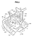
- the dash side panel 27R includes a front panel section 27A lying along the dash cross member 5 and a side panel section 27B lying along the front pillar 15R. At a comer where the front and side panel sections 27A and 27B meet each other, the dash side panel 27R has a plurality of generally triangular ribs 29 vertically spaced one after another. As best seen in Figure 5, on the side panel section 27B, the triangular ribs 29 have their end points aligned on a vertical straight line O. The provision of the vertically spaced ribs 29 facilitates rotation of the dash side panel 27R about the straight line O when, during a frontal crash, the dash cross member 5 is subject to the input load through the front side members 10L and 10R.
- the input load-transmitting structure 21 includes a central reinforcement member 22, which is constructed from elongate members in the form of reinforcement beads 25. Each of the reinforcement beads 25 is highly rigid.
- the load-transmitting structure 21 also comprises a pair of side reinforcement members (e.g., 26R) that comprise a plate member that is more rigid than the point where the side reinforcement member 26R of the load-transmitting structure 21 joins the side sill 21R of floor 1.
- the tunnel 1B has an accelerator portion 30 and a limit structure 32 where the reinforcement member 22 joins the tunnel 1B.
- the accelerator portion 30 initiates deformation of the tunnel portion 1B, and the limit structure 32 limits rotation of the reinforcement member 22.
- each of the side sills 1CL, 1CR has accelerator portions 30 and limit structures 32, respectively, at portions where the side reinforcement members 26 join the side sills 1CL, 1CR.
- the accelerator portions 30 of the side sills 1CL, 1CR initiate deformation and the limit structures 32 limit rotation of the side reinforcement members 26.
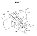
- the accelerator portion 30 and the limit structure 32 will now be described with reference to Figures 7 to 9.
- the accelerator portion 30 is in the form of a weak portion 31, which is formed within the upper surface of the tunnel 1B.
- the weak portion 31 has a variation in rigidity between the inner and outer walls 2, 3, which is created by reducing the thickness of the inner wall 2 and increasing the thickness of the outer wall 3.
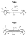
- the weak portion 31 may include a plurality of apertures 31a formed within the inner wall 2 at the upper surface of the tunnel 1B.
- the weak portion 31 may be comprised of a recess 31b formed within the inner wall at the upper surface of the tunnel 1B.
- the dash cross member 5 is subject to an input load through the front side members 10L and 10R.
- the input load-transmitting structure 21, which includes the reinforcement members 22 and 26, applies the input load to the tunnel 1B and the side sills 1CL and 1CR of the floor 1 at substantially right angles to bend each outwardly of the vehicle cabin P•C.
- the amount of energy absorption due to deformation of the floor 1 in the bending direction adds to the amount of energy absorption due to deformation of the front side members 10L and 10R in their longitudinal direction.
- the load is applied to the floor 1 at substantially right angles to the surface portions to facilitate deformation of the floor 1 toward the exterior of the passenger cabin.
- the reaction of the vehicle cabin to the input load can be suppressed to a sufficiently low level because of the deformation of the floor 1 in the bending direction.
- a reduction in the cross sectional area of the floor 1 is no longer needed.
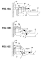
- Figures 10A to 10C schematically illustrate the tunnel 1B buckling at different stages of a full frontal lap crash.
- Figure 10A illustrates the input load F being transmitted through the front side members 10L, 10R, the dash cross member 5 and then the reinforcement member 22 during a frontal crash against a barrier 40.
- the dash cross member 5 supports the front side members 10L, 10R to ensure that the front side members 10L, 10R deform from their forward ends in the longitudinal direction.
- the dash cross member 5 deforms toward the cabin thereby causing the reinforcement member 22 to rotate clockwise as shown in Figure 10B, which causes the input load F to be applied downward on the upper surface of the tunnel 1B at a substantially right angle.
- the dash cross member 5 is sufficiently rigid because it is extruded substantially parallel to the transverse line 52. As a result of the sufficiently high rigidity of the dash cross member 5, the front side members 10L, 10R deform from their forward ends in the longitudinal direction. In addition, the dash cross member 5 distributes the input load to the front pillars 15L, 15R, thereby suppressing the longitudinal application of the load to the floor 1.
- the flexure rigidity of the reinforcement member 22 is higher than the flexure rigidity of the portion where the reinforcement member 22 joins the tunnel 1B.
- the reinforcement member 22 is able to change the direction of the input load applied to the dash cross member 5 before the input load is applied to the tunnel 1B.
- the inner wall 2 begins to deform toward the outer wall 3, which tends to cause the tunnel 1B to bend downward or away from the interior of the passenger cabin.
- the accelerator portion 30 further causes the tunnel 1B to bend downward or away from the passenger cabin.
- the accelerator portion 30 serves to deform the tunnel 1B downward to complete the required downward deformation of the tunnel 1B prior to the time at which the engine 41 and the transmission elements (not shown) contact the dash cross member 5.
- the rotation of the reinforcement member 22 is limited by its abutting engagement with the relatively thick outer wall 3.
- the angle of rotation of the reinforcement member 22 is limited to the minimum amount that is required to initiate the deformation of tunnel 1B.
- the amount of inclination of the dash cross member 5 toward the cabin is limited to the required minimum.
- the load transmission path through the engine 41 from the barrier to the dash cross member 5 is the shortest.
- the engine 41 becomes the input load-transmitting member that transfers the input load F to the dash cross member 5.
- the input load is then applied to the floor 1 along the longitudinal centerline 50 (see Figure 1).
- the forward end portion of the floor 1 has been deformed in a bending direction so that the buckling rigidity of the floor 1 is lowered, which lowers the amount of load that must be applied to initiate buckling of the floor 1. As a result, impact energy is absorbed effectively.
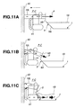
- Figures 11A to 11C illustrate tunnel 1B buckling at different stages during a frontal crash of a vehicle where a reinforcement member is not used.
- the engine 41 and the transmission elements contact the dash cross member 5 as shown in Figure 11C.
- the input load F is applied to the floor 1 along the central longitudinal line 50.
- the floor 1 is not yet deformed, which causes an increase in the load level required to initiate buckling of the floor 1.
- the load level is heavily dependent on the cross-sectional area of the floor 1 and is thus relatively high. Thus, a peak vehicle cabin reaction is relatively high during impact energy absorption.
- the dash cross member 5 is subject to input load F.
- the dash side panels 26R rotate about the straight line O due to the rearward deformation of the dash cross member 5, which is the same as the rotation of the integral reinforcement members 26R. This causes the input load F to be applied to the side surfaces on the inner wall 2 of the side sills 1CL, 1CR substantially at right angles to bend them away from the passenger compartment.
- curve “a” shows the vehicle cabin reaction (cabin G) of the first embodiment during a frontal crash.
- Curve “b” shows the vehicle cabin reaction of the comparative example of Figure 11 (i.e., a load-transmitting structure is not provided) during a frontal crash.
- Figures 10A and 11A correspond to region (A) in Figure 12.
- Figures 10B and 11B correspond to region (B) in Figure 12.
- Figures 10C and 11C correspond to region (C) in Figure 12.
- Region (A) shows the cabin reaction during deformation of front side members 10L and 10R.
- Region (B) shows the cabin reaction during the rearward deformation of the dash cross member 5 toward the cabin.
- P 1 is the time at which the floor 1 begins to buckle.
- P 2 is the time at which the engine 41 contacts the dash cross member 5 in the first embodiment.
- P 3 is the time at which the engine 41 contacts the dash cross member 5 in the comparative example.
- a comparison of curves "a" and "b” reveals that, during region (A), there is no difference between the first embodiment and the comparative example.
- region (B) the cabin reaction drops more after the floor 1 begins to buckle in the first embodiment than it does in the comparative example.
- the average cabin reaction Ga of the first embodiment in region (C) is lower than the average cabin reaction Gb of the comparative example. Accordingly, the average cabin reaction has been reduced from Gb to Ga as a result of the input load-transmitting structure 21.
- the floor 1 includes a first recess that is recessed inwardly between the left-hand side sill 1CL and the tunnel 1B and a second recess that is recessed inwardly between the right-hand side sill 1CR and the tunnel 1B.
- the dash cross member 5 includes a pair of teeth SDL, SDR that are formed integrally to the toe boar section 5A. Each tooth 5DL, 5DR is inserted into the corresponding recess of floor 1.
- the input load-transmitting structure 21 connects the dash cross member 5 and a forward end of floor 1.
- the forward end portion of floor 1 to which the input load-transmitting structure 21 is connected extends beyond the first and second floor panel portions 1AL, 1AR toward the toe board section 5A.
- the two heads arrows indicate the directions in which the floor 1 and the dash cross member 5 are extruded.
- the integral portions 5DL, 5DR are extruded in the first direction, whereas the floor panel portions 1AL, 1AR are extruded in the second direction.
- the forward end portion of the floor 1 to which the reinforcement members 22, 26 are connected has a lower flexure rigidity than the floor panel portions 1AL, 1AR.
- Figure 15 shows a simplified beam model that demonstrates the relationship between the teeth 5DL, 5DR and the floor panel portions 1AL and 1AR.
- the teeth 5DL, 5DR are smaller than the floor panels 1AL, 1AR and the former is less rigid than the latter.
- the forward end portion of the floor 1 is deformed downward while the input load is still low, which results in a reduced cabin reaction.
- the reference letter L indicates the amount by which each of the teeth 5DL, 5DR extends beyond the lower edge of toe board section 5A, that is, the offset L also is the length of the recess of the floor 1 in the longitudinal direction.
- the rigidity of the floor 1 can be adjusted by varying the offset L.
- varying the offset L may vary cabin rigidity in response to vehicle weight. It is preferable that, as the vehicle weight increases, the cabin rigidity will also increase. Thus, as vehicle weight increases, the offset L should decrease. As demonstrated in Figures 16 to 18, decreasing the offset L to a small amount La, increases the flexure rigidity of the floor 1.
- the offset L can be adjusted to the desired amount depending on whether the flexure rigidity must be increased or decreased, which will then achieve the required cabin rigidity.
- the second embodiment of the invention will now be described with reference to Figures 19 to 21.
- the second embodiment is substantially the same as the first embodiment with the addition of an instrument stay 34, which supports an instrument panel (not shown).
- the upper end of the instrument stay 34 is connected to a steering member 33.
- the ends of the steering member 33 are connected to the front pillars 15L, 15R.
- the steering member 33 supports a steering column bracket 38 and a steering column 35.
- the steering column 35 is coupled to a steering wheel 36, which is disposed in the interior of the passenger compartment so that a driver can steer the vehicle.
- a steering rack 37 is disposed outside of the passenger compartment and is coupled to the steering wheel 36 via the steering column 35.
- the lower end of the instrument stay 34 is connected to the upper surface of tunnel 1B adjacent to the connecting point of the reinforcement member 22 and the upper surface of the tunnel 1B.
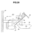
- the steering mechanism Prior to a crash, the steering mechanism is positioned as shown by the dotted lines in Figure 21.
- the tunnel 1B is deformed by reinforcement member 22, which causes the instrument stay 34 and the steering member 33 to be drawn downward to the position shown in Figure 21.
- the steering wheel is drawn downward and away from a vehicle operator, rather than being thrust toward the operator.
- the tunnel 1B is formed as a dual-wall structure. If desired, however, a tunnel 1B constructed of a single wall may be used. If the single wall structure is used, then a conventional mechanical fastener, such as a bolt may be used to attach parts to the tunnel.
- the floor 1 may be constructed of a single extruded part or may be an assembly of different extruded parts. If a multiple part floor is used, then the floor may be assembled using a variety of techniques, such as welding or mechanical fastening (e.g., tongue and groove fastening).
- the floor 1 being constructed from extruded parts of a light metal, such as an aluminum alloy, is effective in reducing the weight of the vehicle without decreasing the rigidity of the floor 1.
- the floor has two spaced walls and partitions to define a plurality of parallel channels that extend substantially parallel to the longitudinal centerline of the vehicle.
- the floor has a substantially uniform cross-section along its entire longitudinal length.
Landscapes
- Engineering & Computer Science (AREA)
- Chemical & Material Sciences (AREA)
- Combustion & Propulsion (AREA)
- Transportation (AREA)
- Mechanical Engineering (AREA)
- Body Structure For Vehicles (AREA)
Abstract
Description
- The present invention relates to a vehicle structure and, more particularly, to a vehicle structure having a unique impact absorbing arrangement.
- A vehicle structure is disclosed in JP-A 10-203422 in which extension members are provided in the vehicle structure. The extension members extend into front side members and are connected to a dash cross member and to a compression rod mounting reinforcement, which is also connected to the dash cross member. With this structure, an input load, which is received by front ends of the extension members, is well distributed to the dash cross member.
- The dash panel, however, is constructed from pressed parts, which are relatively weak. Due to the weakness of the pressed parts, an extension member is provided along the lower surface of the vehicle floor. The extension member transmits an impact load to the floor as the pressed parts of the dash cross member are not relatively strong. Because the dash panel cannot widely distribute the input load, the extension member provides a path for the input load. To alleviate any distortion caused by the impact load being concentrated at the extension member, the extension member and its mounting sites must be reinforced, which undesirably increases the weight of the vehicle.
- According to the present invention, there is provided a vehicle as set out in accompanying
claims claims - There is a need for a vehicle structure having reduced weight that is capable of withstanding high impact loads.
- There is also a need for a vehicle structure in which the passenger compartment is subject to a reduced cabin reaction force.
- There is also a need for a vehicle structure that is capable of changing the direction of an impact load resulting from a frontal crash from a horizontal direction to a vertical direction.
- These and other needs are satisfied by an embodiment of the invention, which provides a vehicle having a cabin and including a centerline extending in forward and rearward directions and a transverse line intersecting the centerline. The vehicle has a cross member extending in a first direction parallel to the transverse line. An extruded floor is connected to the cross member to partially define the cabin. The floor extends in a second direction, which is parallel to the centerline, and has first and second side sills, which are spaced from each other in the first direction and extend in the second direction. The first and second side sills have forward ends contacting the cross member. The vehicle also has at least one load-transmitting member disposed between the cross member and the floor. Each load-transmitting member applies an impact load from the cross member to the floor at a substantially right angle to the floor.
- Additional advantages and novel features of the invention will be set forth in part in the following description, and, in part, will be apparent to those skilled in the art after examining the following or by practicing the invention. The advantages of the invention may be realized and attained via the instrumentalities and combinations particularly pointed out in the appended claims.
- Preferred embodiments of the invention will be described with reference to the attached drawings, which are incorporated in and constitute a part of the specification, in which:
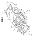
- Figure 1 is a perspective view of an exemplary vehicle to which the embodiments of the invention may be applied;
- Figure 2 is a sectional perspective view of the vehicle of Figure 1 including a first embodiment of the present invention;
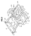
- Figure 3 is a perspective view of the front portion of the vehicle of Figure 1 including the first embodiment of the present invention;
- Figure 4 is an exploded view of the vehicle structure shown in Figure 3;
- Figure 5 is a fragmentary view of Figure 2;
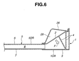
- Figure 6 is a section taken through the line 6-6 of Figure 5;
- Figure 7 is a fragmentary view of Figure 5;
- Figure 8 is a section taken through the line 8-8 of Figure 7;
- Figure 9 is a modified section of Figure 8;
- Figures 10A to 10C are schematic side views illustrating three consecutive states of the first embodiment during a frontal crash;
- Figures 11A to 11C are similar views to Figures 10A to 10C, respectively, of the parts of a prior art example;
- Figure 12 is a graph of a frontal crash test conducted with a vehicle constructed according to the first embodiment of the invention compared to a full frontal lap crash conducted with a vehicle constructed according to the prior art example of Figures 11A to 11C;
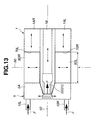
- Figure 13 is a simplified schematic plan view of the relationship between the front side members, the dash cross member and the floor of the first embodiment of the invention;
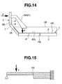
- Figure 14 is a simplified schematic side view of the dash cross member and the floor of Figure 13;
- Figure 15 is a beam model of the structure shown in Figures 13 and 14;
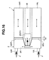
- Figure 16 is a simplified schematic plan view of the relationship between the front side members, the dash cross member and the floor of the first embodiment of the invention, illustrating a modification of the relationship between the dash cross member and the floor;
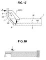
- Figure 17 is a simplified schematic side view of the dash cross member and floor shown in Figure 16;
- Figure 18 is a beam model of the structure shown in Figures 16 and 17;
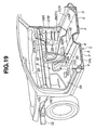
- Figure 19 is a sectional perspective view of the vehicle of Figure 1 including a second embodiment of the present invention;
- Figure 20 is a view similar to Figure 10A illustrating the position of parts of the second embodiment of the invention at the initiation of a frontal crash; and
- Figure 21 is a view similar to Figure 10C illustrating the position of parts of the second embodiment of the invention at the final stage of a frontal crash.
-
- Referring now to the drawings, and initially to Figure 1, there will be seen a vehicle superstructure or a vehicle body structure having a cabin or passenger compartment P•C, a front compartment F•C, and a rear compartment R•C. Each embodiment of the invention described herein is implemented in a forward portion of the vehicle and includes a dash cross member and an extruded floor. The present invention is equally applicable to a rearward portion of the vehicle including a rear cross member and a floor.
- The first embodiment of the invention will now be described with reference to Figures 1 to 8. As shown in Figure 1, the vehicle has a
longitudinal centerline 50 and atransverse line 52, which is perpendicular to thelongitudinal centerline 50. The vehicle body structure comprises anextruded floor 1 and adash cross member 5. Thefloor 1 extends rearward from thedash cross member 5 along thelongitudinal centerline 50. At its rear end, thefloor 1 is connected to a rearseat cross member 13. Arear floor panel 14 is connected to and extends rearward from the rearseat cross member 13. - The vehicle body structure includes a left-
hand front pillar 15L, a left-hand center pillar 16L, a left-handrear pillar 17L, and a left-handrear fender 19L, a right-hand front pillar 15R, a right-hand center pillar 16R, a right-hand rear pillar (not shown), a right-handrear fender 19R, and aroof panel 18. Thedash cross member 5, thefloor 1, thefront pillars center pillars rear pillars 17L, the rearseat cross member 13, therear floor panel 14, and theroof panel 18 define a passenger cabin or compartment P•C. - A
forward cross member 11 and abumper armature 12 interconnect the forward end portions offront side members front side members first cross member 11,strut housings bumper armature 12 cooperate with each other to form an end structure for the front compartment F•C, which may serve as an engine room. - The
floor 1 is formed by extruding a light metal material, such as an aluminum alloy, in a first direction, which is substantially parallel to thelongitudinal centerline 50. As best seen in Figure 3, thefloor 1 has two spaced walls, that is, anupper wall 2 and alower wall 3, and partitions orreinforcement walls 4 between the upper andlower walls partitions 4 and the upper andlower walls longitudinal centerline 50. Thepartitions 4 enhance the structural rigidity of thefloor 1. - The
floor 1 includes at least portions of a plurality of floor structural members, which extend rearward from thedash cross member 5 in the second direction. The plurality of structural members include acentral tunnel 1B and a first or left-hand side sill 1CL spaced from thetunnel 1B in a first or leftward direction, which is substantially parallel to thetransverse line 52. The plurality of structural members further includes a second or right-hand side sill 1CR spaced from thetunnel 1B in the first direction. Thefloor 1 includes a first or left-hand floor panel portion 1AL that extends between thetunnel 1B and the first side sill 1CL, and a second or right-hand floor panel portion 1AR that extends between thetunnel 1B and the second side sill 1CR. - The
dash cross member 5 has atoe board section 5A and a vertically extendingwall section 5B that extends from thetoe board section 5A. Acutout 5C is formed substantially at the transverse midpoint of thetoe board section 5A. Similar to thefloor 1, thedash cross member 5 is formed by extruding a light metal material. Thedash cross member 5 is extruded in the first direction, which is substantially parallel to thetransverse line 52. Thedash cross member 5 has two spaced walls, aninner wall 6 and anouter wall 7, andpartitions 8 between the two spacedwalls partitions 8 and the two spacedwalls walls transverse line 52. Thedash cross member 5 has the same cross sectional profile over its entire length along thetransverse line 52. Thepartitions 8 enhance the rigidity of thedash cross member 5. - At best seen in Figure 3, the
cutout 5C in thedash cross member 5 receives thetunnel 1B offloor 1. Referring to Figures 3 and 4, areinforcement structure 9 extends over theouter wall 7 from the vertically extendingwall section 5B to thetoe board section 5A. Thereinforcement structure 9 has two arms, namely a left-hand arm 9AL and a right-hand arm 9AR, both of which extend in the forward direction substantially parallel to thelongitudinal centerline 50. The two arms 9AL, 9AR are spaced along thetransverse line 52 and fixedly support the front left-hand and the right-hand side members - With the
cutout 5C coupled to thetunnel 1B, thetoe board section 5A of thedash cross member 5 is brought into abutting contact with the forward ends of the side sills 1CL and 1CR. An appropriate welding technique, such as laser welding or metal inert gas (MIG) welding, may be used to weld the joint between thetoe board section 5A and the forward ends of the side sills 1CL and 1CR and the joint between thecutout 5C and thetunnel 1B. As will be seen from the following description, a joint between thedash cross member 5 and each of the floor panel portions 1AL and 1AR is offset from the joint between thedash cross member 5 and thetunnel 1B or each of the side sills 1CL and 1CR. - The
floor 1 has a first or left-hand recess that is recessed from the forward end of thefloor 1 away from thedash cross member 5 between thetunnel 1B and the first side sill 1CL. The first recess has a forward edge 1DL that defines the rear edge of the first recess. Thefloor 1 includes a first or left-hand floor panel portion 1AL disposed between thetunnel 1B and the first side sill 1CL. The first floor panel portion 1A has at least aportion 70L of the first recess defining edge 1DL. Thecross member 5 includes a first tooth SDL that extends integrally or unitarily from thetoe board section 5A toward the first panel portion 1AL. The first tooth SDL engages the first recess and is connected to thefloor 1 along the first recess defining edge 1DL. - The
floor 1 has a second or right-hand recess that is recessed from the forward end of the floor away from thedash cross member 5 between thetunnel 1B and the second side sill 1CR. The second recess has a forward edge 1DR that defines the second recess rear edge of the second recess. Thefloor 1 includes a second or right-hand floor panel portion 1AR disposed between thetunnel 1B and the second side sill 1CR. The second floor panel portion 1AR has at least aportion 70R of the second recess defining edge 1DR. Thecross member 5 includes a second tooth SDR that extends integrally or unitarily from thetoe board section 5A toward the second floor panel portion 1AR. The second tooth SDR engages the second recess and is connected to thefloor 1 along the second recess defining edge 1DR. - As shown in Figure 3, the first and second recesses are rectangular. The first recess extends between a left-hand side lower edge of the
tunnel 1B and an inner lower edge of the first side sill 1CL and in front of the first floor panel portion 1AL. Thus, the left-hand side lower edge of thetunnel 1B, the inner lower edge of the first side sill 1CL, and the forward end of the first floor panel portion 1AL cooperate with each other to complete the first recess defining edge 1DL. The second recess extends between a right-hand side lower edge of thetunnel 1B and an inner lower edge of the second side sill 1CR and in front of the second floor panel portion 1AR. Thus, the right-hand side lower edge of thetunnel 1B, the inner lower edge of the second side sill 1CR, and the forward end of the second floor panel portion 1AR cooperate with each other to complete the second recess defining edge 1DR. - Referring to Figure 4, the first and second teeth 5DL, 5DR are integrally connected to the
toe board section 5A near the lower edge of thetoe board section 5A. The teeth 5DL, 5DR each extend toward, and parallel with, the respective first and second floor panel portions 1AL, 1AR. The first and second teeth 5DL, 5DR are each extruded concurrently with the other portions ofdash cross member 5 and have a substantially uniform cross-section along thetransverse line 52 and include a plurality of channels between the inner andouter walls partitions 8, which interconnect the inner andouter walls tunnel 1B, the floor panel portions 1AL, 1AR, and the side sills 1CL, 1CR. - The floor panel portions 1AL, 1AR each have a
forward edge portion transverse line 52. Thetunnel 1B and the side sills 1CL, 1CR project forward beyond theforward edge portions partitions 8 lying along the transverse line 52 (see Figure 1), the forward portion of thefloor 1 exhibits a reduction in flexure rigidity during a frontal crash. - An input load-transmitting
structure 21 is operatively disposed between thedash cross member 5 and thefloor 1. The load-transmittingstructure 21 applies an input load, which thedash cross member 5 is subjected to through theside members floor 1 at generally right angles to bend thefloor 1 outward or away from the vehicle cabin P•C. - The input load-transmitting
structure 21 includes at least a central portion and a pair of side portions. The central portion provides a load delivery path from thedash cross member 5 to thetunnel 1B. Each of the pair of side portions provides a load delivery path from thedash cross member 5 to one of the side sills 1CL, 1CR. According to the first preferred implementation of the present invention, the input load-transmittingstructure 21 is arranged at or around a central or mid location of thefloor 1 and thedash cross member 5. Referring to Figures 2 and 3, at the central location, the input load-transmittingstructure 21 interconnects thedash cross member 5 and the upper surface, i.e., a surface portion of theinner wall 2, of thetunnel 1B. The input load-transmittingstructure 21 is connected to a forward portion of thetunnel 1B that projects beyond the floor panel portions 1AL and 1AR toward thedash cross member 5. - Input load-transmitting structures may also be installed at the sides of the vehicle structure such that the input load-transmitting
structure 21 connects thedash cross member 5 and an inner side surface, i.e., a portion of theinner wall 2, of one of the side sills 1CL, 1CR. The input load-transmittingstructure 21 is connected to a forward portion of the side sill 1CR, for example, that projects beyond the floor panel portions 1AL and 1AR toward the dash cross member. - Each input load-transmitting
structure 21 has a flexure rigidity that is higher than the flexure rigidity of the forward portion of the corresponding one of thetunnel 1B, side sill 1CL, and the side sill 1CR. - In this first embodiment, the input load-transmitting
structure 21 is comprised composed of acentral reinforcement member 22 and a pair of side reinforcement members, only a right-hand one being shown at 26 in Figures 2, 3 and 4. Thecentral reinforcement member 22 is connected to thedash cross member 5 and also to thetunnel 1B in such a manner as to bridge them. During a frontal crash, thedash cross member 5 is subject to an input load through thefront side members 10L and 10A. During such a full frontal lap crash, thereinforcement member 22 rotates clockwise as viewed from the left-hand side of the vehicle, which transfers the input load from a generally horizontal direction downward to a substantially vertical force that acts ontunnel 1B at substantially right angles. - The
reinforcement member 22 includes abracket 23 that is joined (e.g., by welding) to theinner wall 6 of thedash cross member 5. The reinforcement member also includes abracket 24 that is joined (e.g., by welding) to an upper side portion of theinner wall 2 of thetunnel 1B. A pair ofreinforcement beads 25 interconnect thebrackets - The
side reinforcement members 26 are integral parts of thedash side panels 27R (note that only one of the dash side panels is shown, but that the vehicle also has another dash side panel 27L that is not shown). Theside reinforcement members 26 each extend downward from a lower side of the respectivedash side panels 27R. - As shown in more detail in Figures 5 and 6, the side reinforcement member 26R extends over lower portions of the
dash cross member 5 andfront pillar 15R and the forward end portion of the side sill 1CR. As best seen in Figure 6, the side reinforcement member 26R protrudes inwardly of the passenger cabin P•C to define a closed crosssectional configuration 28. The closedcross-sectional configuration 28 is connected to a comer where thedash cross member 5,front pillar 15R and side sill 1CR meet each other. The closedcross-sectional configuration 28 extends diagonally over the comer from thedash cross member 5 toward the forward end portion of the side sill 1CR. The other reinforcement member has the same structure as reinforcement member 26R, but is a mirror image. - The
dash side panel 27R includes afront panel section 27A lying along thedash cross member 5 and aside panel section 27B lying along thefront pillar 15R. At a comer where the front andside panel sections dash side panel 27R has a plurality of generallytriangular ribs 29 vertically spaced one after another. As best seen in Figure 5, on theside panel section 27B, thetriangular ribs 29 have their end points aligned on a vertical straight line O. The provision of the vertically spacedribs 29 facilitates rotation of thedash side panel 27R about the straight line O when, during a frontal crash, thedash cross member 5 is subject to the input load through thefront side members - As demonstrated, the input load-transmitting
structure 21 includes acentral reinforcement member 22, which is constructed from elongate members in the form ofreinforcement beads 25. Each of thereinforcement beads 25 is highly rigid. The load-transmittingstructure 21 also comprises a pair of side reinforcement members (e.g., 26R) that comprise a plate member that is more rigid than the point where the side reinforcement member 26R of the load-transmittingstructure 21 joins the side sill 21R offloor 1. - As shown in Figures 7 and 8, the
tunnel 1B has anaccelerator portion 30 and alimit structure 32 where thereinforcement member 22 joins thetunnel 1B. Theaccelerator portion 30 initiates deformation of thetunnel portion 1B, and thelimit structure 32 limits rotation of thereinforcement member 22. Similarly, each of the side sills 1CL, 1CR hasaccelerator portions 30 andlimit structures 32, respectively, at portions where theside reinforcement members 26 join the side sills 1CL, 1CR. Theaccelerator portions 30 of the side sills 1CL, 1CR initiate deformation and thelimit structures 32 limit rotation of theside reinforcement members 26. - The
accelerator portion 30 and thelimit structure 32 will now be described with reference to Figures 7 to 9. Theaccelerator portion 30 is in the form of aweak portion 31, which is formed within the upper surface of thetunnel 1B. Theweak portion 31 has a variation in rigidity between the inner andouter walls inner wall 2 and increasing the thickness of theouter wall 3. As best seen in Figure 8, theweak portion 31 may include a plurality ofapertures 31a formed within theinner wall 2 at the upper surface of thetunnel 1B. Alternatively, as seen in Figure 9, theweak portion 31 may be comprised of arecess 31b formed within the inner wall at the upper surface of thetunnel 1B. - Making the
outer wall 3 thicker than theinner wall 2 forms thelimit structure 32. Rotation of thereinforcement 22 during a frontal crash first deforms theinner wall 2 toward theouter wall 3 until the inner wall abuttingly engages theouter wall 3. - According to the first embodiment, during a frontal crash, the
dash cross member 5 is subject to an input load through thefront side members structure 21, which includes thereinforcement members tunnel 1B and the side sills 1CL and 1CR of thefloor 1 at substantially right angles to bend each outwardly of the vehicle cabin P•C. As a result, the amount of energy absorption due to deformation of thefloor 1 in the bending direction adds to the amount of energy absorption due to deformation of thefront side members - According to the first embodiment, the load is applied to the
floor 1 at substantially right angles to the surface portions to facilitate deformation of thefloor 1 toward the exterior of the passenger cabin. The reaction of the vehicle cabin to the input load can be suppressed to a sufficiently low level because of the deformation of thefloor 1 in the bending direction. Thus, a reduction in the cross sectional area of thefloor 1 is no longer needed. - Figures 10A to 10C schematically illustrate the
tunnel 1B buckling at different stages of a full frontal lap crash. Figure 10A illustrates the input load F being transmitted through thefront side members dash cross member 5 and then thereinforcement member 22 during a frontal crash against abarrier 40. Subsequently, as shown in Figure 10B, thedash cross member 5 supports thefront side members front side members dash cross member 5 deforms toward the cabin thereby causing thereinforcement member 22 to rotate clockwise as shown in Figure 10B, which causes the input load F to be applied downward on the upper surface of thetunnel 1B at a substantially right angle. - The
dash cross member 5 is sufficiently rigid because it is extruded substantially parallel to thetransverse line 52. As a result of the sufficiently high rigidity of thedash cross member 5, thefront side members dash cross member 5 distributes the input load to thefront pillars floor 1. - In the first embodiment, the flexure rigidity of the
reinforcement member 22 is higher than the flexure rigidity of the portion where thereinforcement member 22 joins thetunnel 1B. Thus, thereinforcement member 22 is able to change the direction of the input load applied to thedash cross member 5 before the input load is applied to thetunnel 1B. When the input load F is applied to the upper surface of thetunnel 1B, theinner wall 2 begins to deform toward theouter wall 3, which tends to cause thetunnel 1B to bend downward or away from the interior of the passenger cabin. Theaccelerator portion 30 further causes thetunnel 1B to bend downward or away from the passenger cabin. Thus, theaccelerator portion 30 serves to deform thetunnel 1B downward to complete the required downward deformation of thetunnel 1B prior to the time at which theengine 41 and the transmission elements (not shown) contact thedash cross member 5. - At the initial stage of the downward deformation of
tunnel 1B, the rotation of thereinforcement member 22 is limited by its abutting engagement with the relatively thickouter wall 3. As a result, the angle of rotation of thereinforcement member 22 is limited to the minimum amount that is required to initiate the deformation oftunnel 1B. Thus, the amount of inclination of thedash cross member 5 toward the cabin is limited to the required minimum. - Immediately after the
engine 41 and the transmission elements contact thedash cross member 5, as shown in Figure 10C, the load transmission path through theengine 41 from the barrier to thedash cross member 5 is the shortest. Thus, theengine 41 becomes the input load-transmitting member that transfers the input load F to thedash cross member 5. The input load is then applied to thefloor 1 along the longitudinal centerline 50 (see Figure 1). Before the load is applied to the floor, the forward end portion of thefloor 1 has been deformed in a bending direction so that the buckling rigidity of thefloor 1 is lowered, which lowers the amount of load that must be applied to initiate buckling of thefloor 1. As a result, impact energy is absorbed effectively. - In contrast to the situation of Figures 10A to 10C, which illustrates the action of the first embodiment of the invention, Figures 11A to 11C illustrate
tunnel 1B buckling at different stages during a frontal crash of a vehicle where a reinforcement member is not used. After the stages shown in Figures 11A and 11B, during a frontal crash, theengine 41 and the transmission elements contact thedash cross member 5 as shown in Figure 11C. Upon and immediately after this contact, the input load F is applied to thefloor 1 along the centrallongitudinal line 50. Thefloor 1 is not yet deformed, which causes an increase in the load level required to initiate buckling of thefloor 1. The load level is heavily dependent on the cross-sectional area of thefloor 1 and is thus relatively high. Thus, a peak vehicle cabin reaction is relatively high during impact energy absorption. - The deformation of the sides of the vehicle will now be described with reference to Figures 5 and 6. During a frontal crash, the
dash cross member 5 is subject to input load F. The dash side panels 26R rotate about the straight line O due to the rearward deformation of thedash cross member 5, which is the same as the rotation of the integral reinforcement members 26R. This causes the input load F to be applied to the side surfaces on theinner wall 2 of the side sills 1CL, 1CR substantially at right angles to bend them away from the passenger compartment. - Referring to Figure 12, curve "a" shows the vehicle cabin reaction (cabin G) of the first embodiment during a frontal crash. Curve "b" shows the vehicle cabin reaction of the comparative example of Figure 11 (i.e., a load-transmitting structure is not provided) during a frontal crash. Figures 10A and 11A correspond to region (A) in Figure 12. Figures 10B and 11B correspond to region (B) in Figure 12. Figures 10C and 11C correspond to region (C) in Figure 12. Region (A) shows the cabin reaction during deformation of
front side members dash cross member 5 toward the cabin. Region (C) that begins with time P2 and shows the cabin reaction during contact of theengine 41 with thedash cross member 5 according to the first embodiment. Region (C) that begins with the time P3 shows the cabin reaction during contact of theengine 41 with thedash cross member 5 according to the comparative example. In Figure 12, P1 is the time at which thefloor 1 begins to buckle. P2 is the time at which theengine 41 contacts thedash cross member 5 in the first embodiment. P3 is the time at which theengine 41 contacts thedash cross member 5 in the comparative example. - A comparison of curves "a" and "b" reveals that, during region (A), there is no difference between the first embodiment and the comparative example. In region (B), the cabin reaction drops more after the
floor 1 begins to buckle in the first embodiment than it does in the comparative example. Also, the average cabin reaction Ga of the first embodiment in region (C) is lower than the average cabin reaction Gb of the comparative example. Accordingly, the average cabin reaction has been reduced from Gb to Ga as a result of the input load-transmittingstructure 21. - Referring now Figures 3 and 13 to 15, the
floor 1 includes a first recess that is recessed inwardly between the left-hand side sill 1CL and thetunnel 1B and a second recess that is recessed inwardly between the right-hand side sill 1CR and thetunnel 1B. Thedash cross member 5 includes a pair of teeth SDL, SDR that are formed integrally to thetoe boar section 5A. Each tooth 5DL, 5DR is inserted into the corresponding recess offloor 1. The input load-transmittingstructure 21 connects thedash cross member 5 and a forward end offloor 1. The forward end portion offloor 1 to which the input load-transmittingstructure 21 is connected extends beyond the first and second floor panel portions 1AL, 1AR toward thetoe board section 5A. In Figure 13, the two heads arrows indicate the directions in which thefloor 1 and thedash cross member 5 are extruded. The integral portions 5DL, 5DR are extruded in the first direction, whereas the floor panel portions 1AL, 1AR are extruded in the second direction. The forward end portion of thefloor 1 to which thereinforcement members floor 1 is able to deform during the initial stages of a frontal crash even though the magnitude of the input load is still quite low, which results in a further reduction in cabin reaction. - Figure 15 shows a simplified beam model that demonstrates the relationship between the teeth 5DL, 5DR and the floor panel portions 1AL and 1AR. As seen from Figure 15, the teeth 5DL, 5DR are smaller than the floor panels 1AL, 1AR and the former is less rigid than the latter. Thus, if the input load is applied at a substantially right angle to the upper surface of
tunnel 1B, the forward end portion of thefloor 1 is deformed downward while the input load is still low, which results in a reduced cabin reaction. - In Figure 13, the reference letter L indicates the amount by which each of the teeth 5DL, 5DR extends beyond the lower edge of
toe board section 5A, that is, the offset L also is the length of the recess of thefloor 1 in the longitudinal direction. The rigidity of thefloor 1 can be adjusted by varying the offset L. Thus, varying the offset L may vary cabin rigidity in response to vehicle weight. It is preferable that, as the vehicle weight increases, the cabin rigidity will also increase. Thus, as vehicle weight increases, the offset L should decrease. As demonstrated in Figures 16 to 18, decreasing the offset L to a small amount La, increases the flexure rigidity of thefloor 1. Thus, the offset L can be adjusted to the desired amount depending on whether the flexure rigidity must be increased or decreased, which will then achieve the required cabin rigidity. - The second embodiment of the invention will now be described with reference to Figures 19 to 21. The second embodiment is substantially the same as the first embodiment with the addition of an
instrument stay 34, which supports an instrument panel (not shown). The upper end of theinstrument stay 34 is connected to a steeringmember 33. As best seen in Figure 19, the ends of the steeringmember 33 are connected to thefront pillars member 33 supports asteering column bracket 38 and asteering column 35. Thesteering column 35 is coupled to asteering wheel 36, which is disposed in the interior of the passenger compartment so that a driver can steer the vehicle. Asteering rack 37 is disposed outside of the passenger compartment and is coupled to thesteering wheel 36 via thesteering column 35. The lower end of theinstrument stay 34 is connected to the upper surface oftunnel 1B adjacent to the connecting point of thereinforcement member 22 and the upper surface of thetunnel 1B. - Prior to a crash, the steering mechanism is positioned as shown by the dotted lines in Figure 21. During a frontal crash, the
tunnel 1B is deformed byreinforcement member 22, which causes theinstrument stay 34 and the steeringmember 33 to be drawn downward to the position shown in Figure 21. As a result, the steering wheel is drawn downward and away from a vehicle operator, rather than being thrust toward the operator. - In each of the preceding embodiments, the
tunnel 1B is formed as a dual-wall structure. If desired, however, atunnel 1B constructed of a single wall may be used. If the single wall structure is used, then a conventional mechanical fastener, such as a bolt may be used to attach parts to the tunnel. - With regard to the
floor 1, it may be constructed of a single extruded part or may be an assembly of different extruded parts. If a multiple part floor is used, then the floor may be assembled using a variety of techniques, such as welding or mechanical fastening (e.g., tongue and groove fastening). - The
floor 1 being constructed from extruded parts of a light metal, such as an aluminum alloy, is effective in reducing the weight of the vehicle without decreasing the rigidity of thefloor 1. In the preferred embodiment, the floor has two spaced walls and partitions to define a plurality of parallel channels that extend substantially parallel to the longitudinal centerline of the vehicle. Thus, the floor has a substantially uniform cross-section along its entire longitudinal length. When an input load is applied in the longitudinal direction, the floor is able to withstand, without any deformation, a load that is several times as great as the maximum load that may be applied at right angles to the surface of the floor without inducing any bending. - Although the invention has been described with reference to a limited number of embodiments, the scope of invention is not limited thereto. That is to say, various modifications and variations of the embodiment(s) described above will be readily self-evident to those skilled in the art given the preceding disclosure.
Claims (29)
- A vehicle having a cabin (P.C) and including a centerline (50) extending in forward and rearward directions and a transverse line (52) intersecting the centerline, comprising:a cross member (5) extending in a first direction parallel to the transverse line;an extruded floor (1) connected to the cross member to partially define the cabin and extending in a second direction parallel to the centerline and having first and second side sills (1CL, 1CR) spaced from each other in the first direction and extending in the second direction, the first and second side sills having forward ends contacting the cross member; andat least one load-transmitting member (21) disposed between the cross member and the floor, each of the at least one load-transmitting member being arranged to apply an impact load from the cross member to the floor at substantially right angles to the floor.
- A vehicle as claimed in claim 1, wherein the floor further includes a tunnel (1B) disposed between the first and second side sills substantially along the centerline and having a forward end contacting the cross member,
wherein one of the at least one load-transmitting member connects the cross member and the tunnel. - A vehicle as claimed in claim 1 or claim 2, wherein one of the at least one load-transmitting member connects the cross member and the first side sill and another of the at least one load transmitting member (26) connects the cross member and the second side sill.
- A vehicle as claimed in claim 1, claim 2 or claim 3, wherein one of the at least one load-transmitting member includes a plurality of elongate members (25) extending in parallel from the cross member to the floor.
- A vehicle as claimed in claim 1, claim 2 or claim 3, wherein one of the at least one load-transmitting member includes a plurality of plate members disposed in parallel and connecting the cross member and one of the first and second side sills.
- A vehicle as claimed in any one of the claims 1 to 5, wherein the floor includes a deformation portion (30) to initiate a deformation of the floor.
- A vehicle as claimed in claim 6, wherein the deformation portion includes a weakened portion (31) that is weaker than the remaining portion of the floor.
- A vehicle as claimed in claim 6 or claim 7, wherein the deformation portion includes at least one aperture (31a).
- A vehicle as claimed in claim 6, claim 7 or claim 8, wherein the deformation portion includes a recess.
- A vehicle as claimed in any one of the claims 1 to 9, wherein the floor has an upper layer (2), a lower layer (3) disposed below the upper layer and substantially parallel to the upper layer, and a plurality of ribs (4) connecting the upper and lower layers to define a plurality of channels.
- A vehicle as claimed in claim 10, wherein each of the at least one load-transmitting member is connected to the upper layer of the floor.
- A vehicle as claimed in claim 3 when dependent from claim 2, wherein each of the three load-transmitting members includes a reinforcement member rotationally connecting the cross member and the respective tunnel, first side sill and second side sill, and wherein each of the reinforcement members rotates when receiving an impact load.
- A vehicle as claimed in claim 12, wherein the floor further includes a rotation limiting structure to limit rotation of each of the reinforcement members.
- A vehicle as claimed in claim 2, wherein the cross member includes an upright wall section (5B) extending substantially vertically, a toe board section (5A) extending rearward at an angle from the cross member, and first (5DL) and second (5DR) teeth extending rearward substantially horizontally from the toe board section,wherein the floor further includes a first floor panel (lAL) disposed between the first side sill and the tunnel and having a forward edge at least partially recessed from the forward ends of the first side sill and the tunnel to define a first recess that receives the first tooth, andwherein the floor further includes a second floor panel (1AR) disposed between the second side sill and the tunnel and having a forward edge at least partially recessed from the forward ends of the second side sill and the tunnel to define a second recess that receives the second tooth.
- A vehicle as claimed in claim 14, wherein one of the at least one load-transmitting member is connected to the floor forward of the forward edges of the first and second floor panels.
- A vehicle as claimed in claim 15, wherein a length of the first and second teeth decreases as a weight of the vehicle increases.
- A vehicle as claimed in claim 2, wherein the tunnel has only a single layer.
- A vehicle as claimed in claim 3 when dependent from claim 2, further comprising first and second side members having rearward ends connected to the cross member, wherein during a frontal impact to the vehicle, the impact load resulting from the frontal impact is transmitted from the first and second side members to the cross member to each of the three load-transmitting members and to the floor.
- A vehicle having a cabin (P.C) and including a centerline (50) extending in forward and rearward directions and a transverse line (52) intersecting the centerline, comprising:a cross member (5) extending in a first direction parallel to the transverse line;an extruded floor (1) connected to the cross member to partially define the cabin and extending in a second direction parallel to the centerline and having first and second side sills (1CL, 1CR) spaced from each other in the first direction and extending in the second direction, the first and second side sills having forward ends contacting the cross member; andmeans (21) for transferring an impact load resulting from a vehicle impact from the cross member to the floor at substantially right angles to the floor.
- A vehicle as claimed in claim 19, wherein the means for applying an impact load resulting from a vehicle impact from the cross member to the floor at substantially right angles to the floor is arranged to bend the cabin outwardly.
- A vehicle having a cabin (P.C) and including a centerline (50) extending in forward and rearward directions and a transverse line (52) intersecting the centerline, comprising:a cross member (5) extending in a first direction parallel to the transverse line;an extruded floor (1) connected to the cross member to partially define the cabin and extending in a second direction parallel to the centerline and having first and second side sills (1CL, 1CR) spaced from each other in the first direction and extending in the second direction, the first and second side sills having forward ends contacting the cross member; andmeans for bending the cabin outwardly during a vehicle impact.
- A vehicle having an engine compartment (F.C), a cabin (P.C) extending rearward from the engine compartment, a rear compartment (R.C) extending rearward from the cabin, a centerline (50) extending in forward and rearward directions and a transverse line (52) intersecting the centerline, comprising:an extruded cross member (5) extending in a first direction parallel to the transverse line and having:an upright wall section (SB) extending substantially vertically;a toe board section (5A) extending rearward at an angle from the upright wall section; andfirst (5DL) and second (5DR) teeth extending rearward substantially horizontally from the toe board section;first (10L) and second (10R) side members having rear ends connected to the cross member to partially define the engine compartment;an extruded floor (1) connected to the cross member opposite the first and second floor members to partially define the cabin and extending in a second direction parallel to the centerline and having:first (1CL) and second (1CR) side sills spaced from each other in the first direction and extending in the second direction, the first and second side sills having forward ends contacting the cross member;a tunnel (1B) extending along the centerline between the first and second side sills and having a forward end contacting the cross member;a first floor panel (lAL) extending between the first side sill and the tunnel and having a forward edge recessed from the forward ends of the first side sill and the tunnel to define a first recess that received the first tooth, anda second floor panel (1AR) extending between the second side sill and the tunnel and having a forward edge recessed from the forward ends of the second side sill and the tunnel to define a second recess that receives the second tooth; anda first load-transmitting member (21) disposed between the cross member and the tunnel such that during an impact, an impact load is transmitted from the first and second side members to the cross member to the tunnel at substantially right angles to the tunnel.
- A vehicle as claimed in claim 22, further comprising:a second load-transmitting member disposed between the cross member and the first side sill such that during impact, the impact load is transmitted from the first and second side members to the cross member to the first side sill at substantially right angles to the first side sill; anda third loading-transmitting member (26) disposed between the cross member and the second side sill such that during impact, the impact load is transmitted from the first and second side members to the cross member to the second side sill at substantially right angles to the second side sill.
- A vehicle as claim in claim 2 or claim 23, further comprising:a steering member (33) disposed through the cross member; anda stay (34) having an upper end connected to the steering member and a lower connected to the tunnel in the vicinity of a connection point of the one of the at least one load-transmitting member to the tunnel.
- A vehicle body structure for a vehicle having a centerline (50) extending in forward and rearward directions and a transverse line (52) intersecting the centerline, comprising:a cross member (5) extending in a first direction parallel to the transverse line;an extruded floor (1) connected to the cross member and extending in a second direction parallel to the centerline and having first (1CL) and second (1CR) side sills spaced from each other in the first direction and extending in the second direction, the first and second side sills having forward ends contacting the cross member; andat least one load-transmitting member (21) disposed between the cross member and the floor, each of the at least one load-transmitting member applies an impact load from the cross member to the floor at substantially right angles to the floor.
- A vehicle body structure as claimed in claim 25, wherein the floor further includes a tunnel (1B) disposed between the first and second side sills substantially along the centerline and having a forward end contacting the cross member,
wherein a first of the at least one load-transmitting member connects the cross member and the tunnel. - A vehicle body structure as claimed in claim 26, wherein a second of the at least one load-transmitting member connects the cross member and the first side sill, and
wherein a third (26) of the at least one load-transmitting member connects the cross member and the second side sill. - A vehicle body structure for a vehicle having a centerline (50) extending in forward and rearward directions and a transverse line (52) intersecting the centerline, comprising:a cross member (5) extending in a first direction parallel to the transverse line;an extruded floor (1) connected to the cross member and extending in a second direction parallel to the centerline; andat least one load-transmitting member (21) disposed between the cross member and the floor, each of the at least one load-transmitting member applies an impact load from the cross member to the floor at substantially right angles to the floor.
- A vehicle having a cabin (P.C) and including a centerline (50) extending in forward and rearward directions and a transverse line (52) intersecting the centerline, comprising:a cross member (5) extending in a first direction parallel to the transverse line;an extruded floor (1) connected to the cross member to partially define the cabin and extending in a second direction parallel to the centerline and having first (1CL) and second (1CR) side sills spaced from each other in the first direction and extending in the second direction, the first and second side sills having forward ends contacting the cross member; andmeans (30) for predeforming the floor outward to provide for increased absorption of an impact of an engine into the cabin during a vehicle collision.
Applications Claiming Priority (2)
| Application Number | Priority Date | Filing Date | Title |
|---|---|---|---|
| JP2000040986 | 2000-02-18 | ||
| JP2000040986A JP3828329B2 (en) | 2000-02-18 | 2000-02-18 | Auto body structure |
Publications (3)
| Publication Number | Publication Date |
|---|---|
| EP1125829A2 true EP1125829A2 (en) | 2001-08-22 |
| EP1125829A3 EP1125829A3 (en) | 2002-05-15 |
| EP1125829B1 EP1125829B1 (en) | 2010-04-28 |
Family
ID=18564283
Family Applications (1)
| Application Number | Title | Priority Date | Filing Date |
|---|---|---|---|
| EP00308308A Expired - Lifetime EP1125829B1 (en) | 2000-02-18 | 2000-09-22 | Vehicle structure with load transmission elements |
Country Status (4)
| Country | Link |
|---|---|
| US (1) | US6688676B1 (en) |
| EP (1) | EP1125829B1 (en) |
| JP (1) | JP3828329B2 (en) |
| DE (1) | DE60044288D1 (en) |
Cited By (8)
| Publication number | Priority date | Publication date | Assignee | Title |
|---|---|---|---|---|
| EP1069027A3 (en) * | 1999-07-15 | 2002-03-06 | Nissan Motor Company, Limited | Vehicle body structure |
| WO2002055364A1 (en) * | 2001-01-16 | 2002-07-18 | Fiat Auto S.P.A. | A motor vehicle having a modular structure and a method for assembling it |
| CN101596917B (en) * | 2008-04-24 | 2014-11-05 | Gm全球科技运作股份有限公司 | Frame structure for a motor vehicle |
| CN104428195A (en) * | 2012-06-27 | 2015-03-18 | 日产自动车株式会社 | Vehicle-cabin body structure |
| FR3029883A1 (en) * | 2014-12-12 | 2016-06-17 | Peugeot Citroen Automobiles Sa | MOTOR VEHICLE WITH IMPACT ROOM IN THE CENTRAL TUNNEL. |
| CN106314565A (en) * | 2016-09-20 | 2017-01-11 | 奇瑞汽车股份有限公司 | Automobile head board |
| ITUA20164332A1 (en) * | 2016-06-13 | 2017-12-13 | Claudio Buccini | DEVICE FOR FITTING SEATS FOR VEHICLES |
| EP3613656A1 (en) * | 2018-08-07 | 2020-02-26 | Toyota Jidosha Kabushiki Kaisha | Vehicle front portion structure |
Families Citing this family (42)
| Publication number | Priority date | Publication date | Assignee | Title |
|---|---|---|---|---|
| JP4536994B2 (en) * | 2002-07-10 | 2010-09-01 | 富士重工業株式会社 | Car |
| KR20060009097A (en) * | 2004-07-20 | 2006-01-31 | 현대자동차주식회사 | Lower support structure of cowl cross member |
| JP4635576B2 (en) * | 2004-11-18 | 2011-02-23 | マツダ株式会社 | Toe board reinforcement structure for vehicles |
| JP4655654B2 (en) * | 2005-02-04 | 2011-03-23 | 日産自動車株式会社 | Lower body structure |
| JP4828987B2 (en) * | 2006-03-31 | 2011-11-30 | 本田技研工業株式会社 | Body cover structure for seat type vehicles |
| JP5190216B2 (en) * | 2007-03-30 | 2013-04-24 | 三菱自動車工業株式会社 | Body frame structure |
| EP1980437B1 (en) * | 2007-04-13 | 2011-12-21 | Mazda Motor Corporation | Front structure of vehicle |
| JP5149059B2 (en) * | 2008-04-09 | 2013-02-20 | 富士重工業株式会社 | Body front structure |
| JP5417878B2 (en) * | 2008-05-09 | 2014-02-19 | 日産自動車株式会社 | Rear structure of automobile body |
| DE102008036870A1 (en) * | 2008-08-07 | 2010-02-11 | Dr. Ing. H.C. F. Porsche Aktiengesellschaft | vehicle body |
| JP2010228712A (en) * | 2009-03-30 | 2010-10-14 | Isuzu Motors Co (Thailand) Ltd | Vehicular body front part structure |
| DE102009039807A1 (en) * | 2009-09-02 | 2011-03-03 | GM Global Technology Operations, Inc., Detroit | Front structure for opel corsa car, has frame profiles supported against wall by supporting profiles such that forces or force components are introduced into bar, where supporting profiles are fastened to bar and frame profiles |
| DE102009049113A1 (en) * | 2009-10-12 | 2011-04-14 | GM Global Technology Operations, Inc., Detroit | Vehicle body for motor vehicle, has longitudinal carrier arranged to rear-lateral partition with connected reinforcing strip |
| DE102010002269A1 (en) * | 2010-02-24 | 2011-08-25 | Robert Bosch GmbH, 70469 | Vehicle with deformable passenger compartment |
| JP2012076600A (en) | 2010-10-01 | 2012-04-19 | Suzuki Motor Corp | Vehicle floor framework structure |
| DE102010053464A1 (en) * | 2010-12-03 | 2012-06-06 | GM Global Technology Operations LLC | Frame structure for a motor vehicle, rear frame structure and vehicle body |
| KR101140293B1 (en) * | 2011-07-29 | 2012-05-02 | 대원강업주식회사 | Body frame of automotive vehicle using high tensile strength steel tube |
| DE102011089153A1 (en) * | 2011-12-20 | 2013-06-20 | Bayerische Motoren Werke Aktiengesellschaft | Structure for a motor vehicle, in particular a passenger car, and method for producing such a structure |
| JP5077972B1 (en) * | 2012-04-06 | 2012-11-21 | グリーンロードモータース株式会社 | Automotive mainframe and automobile using the same |
| JP5955122B2 (en) * | 2012-06-20 | 2016-07-20 | 本田技研工業株式会社 | Car FRP cabin |
| US20150158532A1 (en) * | 2012-06-08 | 2015-06-11 | Honda Motor Co., Ltd. | Fiber-reinforced plastic cabin for vehicle |
| CN103832487B (en) * | 2012-11-21 | 2017-02-08 | 上汽通用五菱汽车股份有限公司 | Lap joint structure of front side wall outer plate and front wheel cover |
| JP6146661B2 (en) * | 2013-05-17 | 2017-06-14 | スズキ株式会社 | Steering support member structure |
| US9248860B2 (en) * | 2013-07-22 | 2016-02-02 | GM Global Technology Operations LLC | Center tunnel integrated truss architecture |
| CN105593108B (en) * | 2013-10-04 | 2017-10-27 | 本田技研工业株式会社 | Front part structure of vehicle |
| CN103786795B (en) * | 2014-02-12 | 2016-05-25 | 浙江吉利控股集团有限公司 | A kind of passenger car front wall is strengthened structure |
| US9909613B2 (en) | 2014-04-15 | 2018-03-06 | Roller Bearing Company Of America, Inc. | Compression rod having a buckling initiating feature |
| WO2016148057A1 (en) * | 2015-03-17 | 2016-09-22 | 本田技研工業株式会社 | Vehicle body structure |
| JP2017036019A (en) * | 2015-08-14 | 2017-02-16 | 本田技研工業株式会社 | Body structure |
| JP6547772B2 (en) * | 2017-01-24 | 2019-07-24 | トヨタ自動車株式会社 | Vehicle floor structure |
| KR102354133B1 (en) | 2017-07-12 | 2022-01-24 | 현대자동차주식회사 | Support structure of dash panel for vehicle |
| JP7044009B2 (en) * | 2018-08-10 | 2022-03-30 | トヨタ自動車株式会社 | Body structure |
| KR101987116B1 (en) * | 2018-10-31 | 2019-06-10 | 동해금속(주) | Dash panel module for vehicles |
| KR102552505B1 (en) * | 2018-11-13 | 2023-07-06 | 현대자동차주식회사 | Load distrbuting structure for vehicle |
| US10974769B2 (en) * | 2019-01-14 | 2021-04-13 | Fca Us Llc | Vehicle structural systems for sorb impact events |
| JP7248609B2 (en) | 2020-02-05 | 2023-03-29 | トヨタ自動車株式会社 | vehicle structure |
| DE102020117209A1 (en) * | 2020-06-30 | 2021-12-30 | Bayerische Motoren Werke Aktiengesellschaft | Method for manufacturing a body for a motor vehicle and a body for a motor vehicle |
| DE102021111248A1 (en) * | 2021-04-30 | 2022-11-03 | Bayerische Motoren Werke Aktiengesellschaft | Motor vehicle body for an electrically driven motor vehicle |
| CN114919666A (en) * | 2022-06-06 | 2022-08-19 | 蔚来汽车科技(安徽)有限公司 | Vehicle and front cabin framework of vehicle body |
| CN116923561A (en) * | 2023-08-22 | 2023-10-24 | 浙江吉利控股集团有限公司 | Vehicle body assembly and vehicle |
| CN116985919A (en) * | 2023-08-24 | 2023-11-03 | 宜宾凯翼汽车有限公司 | A structure for improving the stiffness of automobile body joints |
| GB2638987A (en) * | 2024-03-05 | 2025-09-10 | Jaguar Land Rover Ltd | Load transmission member |
Citations (1)
| Publication number | Priority date | Publication date | Assignee | Title |
|---|---|---|---|---|
| JPH10203422A (en) | 1997-01-21 | 1998-08-04 | Nissan Motor Co Ltd | Front side member rear structure |
Family Cites Families (33)
| Publication number | Priority date | Publication date | Assignee | Title |
|---|---|---|---|---|
| US3765715A (en) * | 1970-12-03 | 1973-10-16 | Fiat Spa | Reinforcing structural element for vehicle body |
| GB1451675A (en) * | 1973-06-12 | 1976-10-06 | Nissan Motor | Vehicle body construction |
| DE2527385C3 (en) * | 1975-06-19 | 1982-10-07 | Daimler-Benz Ag, 7000 Stuttgart | Floor pan for self-supporting bodies of motor vehicles |
| SE438297B (en) * | 1977-06-03 | 1985-04-15 | Daimler Benz Ag | TO THE TORPED WALL ON A SELF-PREVENTING MOTOR VEHICLE BODY DURING DOWNBACKING CONNECTING LONG-TERM FRONT BALANCE |
| JPS5880377A (en) | 1981-11-06 | 1983-05-14 | Ishikawajima Harima Heavy Ind Co Ltd | Apparatus for coke charging in dry-process coke quenching equipment |
| JPS58128970A (en) * | 1982-01-27 | 1983-08-01 | Mazda Motor Corp | Construction of car body |
| JPS6045179A (en) | 1983-08-10 | 1985-03-11 | 株式会社日立製作所 | Packer |
| JPH0423116Y2 (en) * | 1987-08-11 | 1992-05-28 | ||
| JPH0788904B2 (en) | 1987-09-29 | 1995-09-27 | キョ―ラク株式会社 | Cover boots |
| JPH01158283A (en) | 1987-12-11 | 1989-06-21 | Aisan Ind Co Ltd | Throttle valve opening sensor |
| JPH01170078A (en) | 1987-12-25 | 1989-07-05 | Sumitomo Electric Ind Ltd | Semiconductor substrate with superconductor layer |
| JPH01254476A (en) | 1988-04-04 | 1989-10-11 | Mazda Motor Corp | Lower car body structure for automobile |
| JP3188266B2 (en) * | 1990-12-20 | 2001-07-16 | アウディ アクチェンゲゼルシャフト | Support structure for passenger car body |
| DE69203928T2 (en) * | 1991-05-10 | 1996-03-28 | Mazda Motor | Vehicle assembly process and vehicle body. |
| JPH04334669A (en) | 1991-05-10 | 1992-11-20 | Mazda Motor Corp | Automobile body assembling method and body structure |
| JPH05262263A (en) | 1992-03-18 | 1993-10-12 | Suzuki Motor Corp | Front car body structure of automobile |
| JP2946927B2 (en) | 1992-03-25 | 1999-09-13 | トヨタ自動車株式会社 | Body floor structure |
| DE4313562A1 (en) | 1993-04-26 | 1994-10-27 | Opel Adam Ag | Body for motor vehicles |
| DE4335501C2 (en) | 1993-10-19 | 1995-07-27 | Vaw Ver Aluminium Werke Ag | Motor vehicle floor pan |
| JPH07137660A (en) | 1993-11-19 | 1995-05-30 | Toyota Motor Corp | Body front structure |
| JPH07144611A (en) | 1993-11-22 | 1995-06-06 | Suzuki Motor Corp | Vehicle anti-theft device |
| US5611593A (en) * | 1994-03-16 | 1997-03-18 | Honda Giken Kogyo Kabushiki Kaisha | Automotive floor panel assembly |
| DE4422498C1 (en) | 1994-06-28 | 1995-10-19 | Porsche Ag | Body structure of a passenger car |
| US5580620A (en) * | 1994-09-02 | 1996-12-03 | 21St Century Ltd. | Multiple void layer synthetic resin panels |
| JP3357201B2 (en) * | 1994-10-19 | 2002-12-16 | 本田技研工業株式会社 | Car body front structure |
| JP3329098B2 (en) | 1994-11-04 | 2002-09-30 | 日産自動車株式会社 | Car body floor structure |
| JP3532678B2 (en) | 1995-10-03 | 2004-05-31 | 本田技研工業株式会社 | Partition wall between engine room and cabin |
| AU705222B2 (en) | 1996-02-09 | 1999-05-20 | Toyota Jidosha Kabushiki Kaisha | Front structure of car body, and method of absorbing impact by means of the front structure |
| JP3528408B2 (en) | 1996-03-19 | 2004-05-17 | トヨタ自動車株式会社 | Vehicle body structure |
| DE19630645A1 (en) * | 1996-07-30 | 1998-02-05 | Porsche Ag | Center tunnel for a vehicle, especially a motor vehicle |
| AU6446898A (en) | 1997-03-04 | 1998-09-22 | Alumax Inc. | Controlled deformability of aluminum, or other metal structure |
| DE19724557B4 (en) | 1997-06-11 | 2004-09-16 | Adam Opel Ag | Self-supporting vehicle body |
| JP3311665B2 (en) | 1997-12-25 | 2002-08-05 | ダイハツ工業株式会社 | Car body tunnel reinforcement structure |
-
2000
- 2000-02-18 JP JP2000040986A patent/JP3828329B2/en not_active Expired - Lifetime
- 2000-09-20 US US09/666,476 patent/US6688676B1/en not_active Expired - Fee Related
- 2000-09-22 DE DE60044288T patent/DE60044288D1/en not_active Expired - Lifetime
- 2000-09-22 EP EP00308308A patent/EP1125829B1/en not_active Expired - Lifetime
Patent Citations (1)
| Publication number | Priority date | Publication date | Assignee | Title |
|---|---|---|---|---|
| JPH10203422A (en) | 1997-01-21 | 1998-08-04 | Nissan Motor Co Ltd | Front side member rear structure |
Cited By (12)
| Publication number | Priority date | Publication date | Assignee | Title |
|---|---|---|---|---|
| EP1069027A3 (en) * | 1999-07-15 | 2002-03-06 | Nissan Motor Company, Limited | Vehicle body structure |
| EP1464565A3 (en) * | 1999-07-15 | 2004-10-13 | Nissan Motor Company, Limited | Vehicle body structure |
| WO2002055364A1 (en) * | 2001-01-16 | 2002-07-18 | Fiat Auto S.P.A. | A motor vehicle having a modular structure and a method for assembling it |
| US7140640B2 (en) | 2001-01-16 | 2006-11-28 | Fiat Auto S.P.A. | Motor vehicle having a modular structure and a method for assembling it |
| CN101596917B (en) * | 2008-04-24 | 2014-11-05 | Gm全球科技运作股份有限公司 | Frame structure for a motor vehicle |
| CN104428195A (en) * | 2012-06-27 | 2015-03-18 | 日产自动车株式会社 | Vehicle-cabin body structure |
| EP2868552A4 (en) * | 2012-06-27 | 2015-07-15 | Nissan Motor | BODYWORK OF VEHICLE CABIN BODY |
| FR3029883A1 (en) * | 2014-12-12 | 2016-06-17 | Peugeot Citroen Automobiles Sa | MOTOR VEHICLE WITH IMPACT ROOM IN THE CENTRAL TUNNEL. |
| ITUA20164332A1 (en) * | 2016-06-13 | 2017-12-13 | Claudio Buccini | DEVICE FOR FITTING SEATS FOR VEHICLES |
| WO2017216721A1 (en) * | 2016-06-13 | 2017-12-21 | Buccini Claudio | Device for mounting seats for motor vehicles |
| CN106314565A (en) * | 2016-09-20 | 2017-01-11 | 奇瑞汽车股份有限公司 | Automobile head board |
| EP3613656A1 (en) * | 2018-08-07 | 2020-02-26 | Toyota Jidosha Kabushiki Kaisha | Vehicle front portion structure |
Also Published As
| Publication number | Publication date |
|---|---|
| EP1125829A3 (en) | 2002-05-15 |
| US6688676B1 (en) | 2004-02-10 |
| EP1125829B1 (en) | 2010-04-28 |
| JP2001225766A (en) | 2001-08-21 |
| JP3828329B2 (en) | 2006-10-04 |
| DE60044288D1 (en) | 2010-06-10 |
Similar Documents
| Publication | Publication Date | Title |
|---|---|---|
| EP1125829B1 (en) | Vehicle structure with load transmission elements | |
| EP2105372B1 (en) | Frame structure for an automotive vehicle, automotive vehicle provided therewith and method for providing a frame structure | |
| EP1093995B1 (en) | Vehicle body structure | |
| JP3783546B2 (en) | Vehicle side sill structure | |
| CA2386494C (en) | Automobile body structure | |
| US6447052B2 (en) | Body structure for vehicle | |
| EP1464565B1 (en) | Vehicle body structure | |
| CN100352719C (en) | Car floor beam structure | |
| CN101500881B (en) | Lower structure of vehicle | |
| JP4384206B2 (en) | Auto body structure | |
| EP1642810B1 (en) | Automobile underbody structure | |
| EP4015354B1 (en) | Front vehicle body structure | |
| JP3074647B2 (en) | Automobile with body support structure | |
| JP2876872B2 (en) | Connection structure of vehicle body strength members | |
| JP3687604B2 (en) | Body front structure | |
| KR20230151262A (en) | Vehicle body structure | |
| CN1668498A (en) | Automotive floor reinforcement structure | |
| JP6161038B2 (en) | Auto body structure | |
| JP3692845B2 (en) | Auto body front structure | |
| JP3307870B2 (en) | Car body side sill reinforcement structure | |
| JP3941532B2 (en) | Body structure | |
| JP3321065B2 (en) | Car body frame reinforcement structure | |
| JP3402586B2 (en) | Large bus frame structure | |
| US7083223B2 (en) | Vehicle cab | |
| JP4083078B2 (en) | Auto body front structure |
Legal Events
| Date | Code | Title | Description |
|---|---|---|---|
| PUAI | Public reference made under article 153(3) epc to a published international application that has entered the european phase |
Free format text: ORIGINAL CODE: 0009012 |
|
| 17P | Request for examination filed |
Effective date: 20001019 |
|
| AK | Designated contracting states |
Kind code of ref document: A2 Designated state(s): AT BE CH CY DE DK ES FI FR GB GR IE IT LI LU MC NL PT SE |
|
| AX | Request for extension of the european patent |
Free format text: AL;LT;LV;MK;RO;SI |
|
| PUAL | Search report despatched |
Free format text: ORIGINAL CODE: 0009013 |
|
| AK | Designated contracting states |
Kind code of ref document: A3 Designated state(s): AT BE CH CY DE DK ES FI FR GB GR IE IT LI LU MC NL PT SE |
|
| AX | Request for extension of the european patent |
Free format text: AL;LT;LV;MK;RO;SI |
|
| RIC1 | Information provided on ipc code assigned before grant |
Free format text: 7B 62D 25/20 A, 7B 62D 21/15 B, 7B 62D 29/00 B |
|
| AKX | Designation fees paid |
Designated state(s): DE FR GB |
|
| 17Q | First examination report despatched |
Effective date: 20040423 |
|
| 17Q | First examination report despatched |
Effective date: 20040423 |
|
| GRAP | Despatch of communication of intention to grant a patent |
Free format text: ORIGINAL CODE: EPIDOSNIGR1 |
|
| GRAS | Grant fee paid |
Free format text: ORIGINAL CODE: EPIDOSNIGR3 |
|
| GRAA | (expected) grant |
Free format text: ORIGINAL CODE: 0009210 |
|
| AK | Designated contracting states |
Kind code of ref document: B1 Designated state(s): DE FR GB |
|
| REG | Reference to a national code |
Ref country code: GB Ref legal event code: FG4D |
|
| REF | Corresponds to: |
Ref document number: 60044288 Country of ref document: DE Date of ref document: 20100610 Kind code of ref document: P |
|
| PLBE | No opposition filed within time limit |
Free format text: ORIGINAL CODE: 0009261 |
|
| STAA | Information on the status of an ep patent application or granted ep patent |
Free format text: STATUS: NO OPPOSITION FILED WITHIN TIME LIMIT |
|
| 26N | No opposition filed |
Effective date: 20110131 |
|
| GBPC | Gb: european patent ceased through non-payment of renewal fee |
Effective date: 20100922 |
|
| REG | Reference to a national code |
Ref country code: FR Ref legal event code: ST Effective date: 20110531 |
|
| REG | Reference to a national code |
Ref country code: DE Ref legal event code: R119 Ref document number: 60044288 Country of ref document: DE Effective date: 20110401 |
|
| PG25 | Lapsed in a contracting state [announced via postgrant information from national office to epo] |
Ref country code: FR Free format text: LAPSE BECAUSE OF NON-PAYMENT OF DUE FEES Effective date: 20100930 Ref country code: DE Free format text: LAPSE BECAUSE OF NON-PAYMENT OF DUE FEES Effective date: 20110401 |
|
| PG25 | Lapsed in a contracting state [announced via postgrant information from national office to epo] |
Ref country code: GB Free format text: LAPSE BECAUSE OF NON-PAYMENT OF DUE FEES Effective date: 20100922 |