EP2105372B1 - Frame structure for an automotive vehicle, automotive vehicle provided therewith and method for providing a frame structure - Google Patents
Frame structure for an automotive vehicle, automotive vehicle provided therewith and method for providing a frame structure Download PDFInfo
- Publication number
- EP2105372B1 EP2105372B1 EP09003297A EP09003297A EP2105372B1 EP 2105372 B1 EP2105372 B1 EP 2105372B1 EP 09003297 A EP09003297 A EP 09003297A EP 09003297 A EP09003297 A EP 09003297A EP 2105372 B1 EP2105372 B1 EP 2105372B1
- Authority
- EP
- European Patent Office
- Prior art keywords
- frame
- frame member
- side face
- vehicle
- reinforcement member
- Prior art date
- Legal status (The legal status is an assumption and is not a legal conclusion. Google has not performed a legal analysis and makes no representation as to the accuracy of the status listed.)
- Expired - Fee Related
Links
Images


Classifications
-
- B—PERFORMING OPERATIONS; TRANSPORTING
- B62—LAND VEHICLES FOR TRAVELLING OTHERWISE THAN ON RAILS
- B62D—MOTOR VEHICLES; TRAILERS
- B62D21/00—Understructures, i.e. chassis frame on which a vehicle body may be mounted
- B62D21/15—Understructures, i.e. chassis frame on which a vehicle body may be mounted having impact absorbing means, e.g. a frame designed to permanently or temporarily change shape or dimension upon impact with another body
- B62D21/152—Front or rear frames
Definitions
- the present invention relates to a frame structure for an automotive vehicle, to an automotive vehicle provided therewith and to a method for providing a frame structure for or on a vehicle, and in particular, relates to a structure and method for impact absorption.
- Japanese Patent Laid-Open Publication No. 2003-220977 discloses a frame structure of an automotive vehicle, in which there is provided a frame member which extends substantially straightly in at vehicle longitudinal direction and connects to a dash panel at its rear end portion, the frame member having a bend portion which is operative to bend in a vehicle width direction when a longitudinal impact load acts thereon. According to this structure, an impact energy inputted to the frame member is absorbed by bending of the frame member.
- the frame member since the frame member has a closed cross section which extends in the longitudinal direction, the amount of energy absorption may be greater at a bending start compared to a case in which the frame member has no closed cross section.
- the increase degree of this amount of energy absorption tends to reduce considerable after the bending start, so that there is a concern that the impact energy could not be absorbed properly.
- the side frame members include widthwise rigidity lowering sections, respectively, to allow inward bending of a rear section of each side frame member in a widthwise direction to provide an increased collapsible stroke for thereby effectively absorbing energy in a wide range, typically in a frontal impact.
- Document US 2003/0075951 A1 discloses a body frame structure for vehicle, comprising at least one body frame which includes a brittle section which is formed at a predetermined section in a lengthwise direction of the body frame, wherein the brittle section is more brittle than other sections of the body frame wherein the brittle section is hardened by a hardening treatment so as to become approximately equal to the other sections of the body frame in axial compressive strength.
- Document US 5,984,403 discloses a frame structure for vehicle body with a frame having a box-shaped cross section and a portion bendable when a collision load is applied in a longitudinal direction of the frame in case of a vehicle collision.
- the frame structure comprises a pair of bead portions arranged in a roughly V shape and formed on a least one of two opposite surfaces of the frame in such a direction that a bending moment generated at that bendable portion of the frame can be cancelled by an additional moment generated by the pair of the bead portions in case of a vehicle collision.
- An object of the present invention is to properly increase the amount of energy absorption even after the bending start of the frame member.
- a frame structure for an automotive vehicle comprising a hollow frame member provided so as to extend substantially in a vehicle longitudinal direction and connect to a dash panel at a rear end portion thereof, the frame member having both-side side face portions and upper and lower horizontal face portions so as to have a substantially-rectangular cross section, the frame member having a bend portion which is operative to bend toward one side substantially in a vehicle width direction when a longitudinal impact load acts thereon, and at least one reinforcement member provided inside the frame member at a space which includes the bend portion of the frame member in such a manner that the reinforcement member is off an inner face of one of the side face portions of the frame member which is located on a side opposite to the one side toward which the bend portion bends in an initial state and the reinforcement member comes to contact the inner face of the one of the side face portions of the frame member as the frame member bends at the bend portion during an action of the impact load.
- the reinforcement member provided inside the frame member at the space including the bend portion of the frame member contacts the inner face of the one of the side face portions of the frame member as the frame member bends at the bend portion during the action of the impact load.
- the bending of the frame member can be properly restrained from progressing abruptly after contacting.
- the reinforcement member is deformed after the contacting, the amount of energy absorption can be properly increased with the deformation of the reinforcement member.
- the reinforcement member is configured such that a portion thereof which is operative to come to contact the frame member is located at a position which is closer to the one of the side face portions of the frame member than the other of the side face portions of the frame member.
- the reinforcement member comprises both-side side face portions and a horizontal face portion which is provided at either a lower side or an upper side between the both-side side face portions thereof so as to have a U-shaped or reverse-U-shaped cross section
- the reinforcement member is configured such that one of the side face portions of the reinforcement member which is located on the one side toward which the bend portion bends is joined to the one of the side face portions of the frame member and the other of the side face portions of the reinforcement member comes to contact the inner face of the one of the side face portions of the frame member as the bend portion bends during the action of the impact load.
- the one of the side face portions of the reinforcement member may be easily attached to the one of the side face portions of the frame member via welding.
- the reinforcement member is attached to the one of the side face portions of the frame member in such a manner that a closed cross section is formed together with the one of the side face portions of the frame member.
- the rigidity of the reinforcement member is increased, so that the amount of energy absorption with the contacting can be further increased.
- the reinforcement member is attached to the one of the side face portions of the frame member in such a manner that a closed cross section is formed therewith singly.
- the reinforcement member forms two closed cross sections together with the frame member or singly in such a manner that the two closed cross sections extend in the vehicle longitudinal direction and overlap with each other in the vehicle width direction.
- the amount of energy absorption with the contacting can be further increased.
- the rigidity for the bending in the vehicle width direction is not increased improperly compared to a case in which the two closed cross sections are configured to overlap with each other in the vertical direction.
- the proper energy absorption can be achieved even in a case in which the frame member has a relatively narrow width.
- the frame member is comprised of a pair of frame members which are located away from each other in the vehicle width direction, a vehicle constituting member is provided between the pair of frame members, and the pair of frame members have respective bend portions which are operative to bend outward of the vehicle respectively.
- the frame member which has bent does not contact the vehicle constituting member.
- the impact energy can be properly absorbed avoiding any contact with the vehicle constituting member provided between the frame members.
- the bend portion of the frame member comprises a bead which is formed at the one of the side face portions of the frame member so as to extend substantially vertically in such a manner that the bead is recessed toward the one side in the vehicle width direction which is a bending direction of the bend portion.
- At least one reinforcement member is provided substantially in the vehicle longitudinal direction in such a manner that a front end portion thereof connects to the frame member at a location which is right behind a rear end of the reinforcement member and a rear end portion thereof connects to a vehicle-body constituting member behind the frame member.
- the rear end portion of the frame member can be reinforced.
- part of the energy absorption can be performed by the reinforcement member, so that flexibility of setting the longitudinal length of the reinforcement member and the like can be improved.
- the bend portion of the frame member is comprised of a plurality of portions which have different bending amounts, and the reinforcement member is provided only for one of the portions which has the greatest bending amount.
- an automotive vehicle comprising a frame structure according to the invention or a preferred embodiment thereof.
- a method of providing a frame structure for an automotive vehicle in particular according to the invention or a preferred embodiment thereof, or a method for absorbing energy upon a load acting thereon comprising the steps of:
- a dash panel 2 which at least partly partitions an engine room Z1 with an engine EG from a vehicle compartment Z2 in which a passenger is present is or is to be provided at a front portion of an automotive vehicle 1 of the present embodiment.
- One or more, preferably a pair of hinge pillars 3 which extends substantially vertically and pivotally supports front doors (not illustrated) is provided at or near both-side end portions of the dash panel 2.
- One or more, preferably a pair of apron reinforcements 4, 4 substantially extends forward from upper end portions of the hinge pillars 3.
- One or more, preferably a pair of front side frames 5, 5 substantially extends in a vehicle longitudinal direction preferably substantially in parallel to the apron reinforcements 4, 4 in a plan view so as to be away from each other substantially in a vehicle width direction.
- a wheel house 6 for a front wheel is at least partly provided between the apron reinforcement 4 and the front side frame 5 in the vehicle width direction.
- Plates 7, 7, which are of a plate shape, are to be attached to respective front end portions of the front side frames 5 and the apron reinforcements 4.
- At least one bumper reinforcement 9 is attached to the right and left plates 7, 7 via one or more crush cans 8, 8 so as to substantially extend in the vehicle width direction.
- the crush cans 8, 8 are configured to be crushable substantially in the vehicle longitudinal direction when a longitudinal impact load acts thereon.
- a lower portion of the dash panel 2 curves substantially rearward, and its lower end portion connects to a front end portion of a floor panel 10.
- a tunnel portion 11 is provided at or near the lower portion of the dash panel 2 and the floor panel 10 so as to extend substantially longitudinally at the intermediate or central portion in the vehicle width direction and project upward.
- a rear portion of the front side frame 5 curves substantially downward beside the wheel house 6, and its lower end portion connects to a front end portion of a floor frame 12 which substantially extends in the vehicle longitudinal direction below the floor panel 10 ( FIG. 2 ).
- a side sill 13 extends rearward from a lower end portion of the front hinge pillar 3.
- the side sill 13 has a substantially closed cross section which substantially extends in the vehicle longitudinal direction.
- a lower dash cross member 14 and an upper dash cross member 16 are respectively provided at or near the lower portion and the upper portion of the dash panel 2 so as to interconnect the right and left hinge pillars 3, 3.
- These cross members 14, 16 preferably substantially have a U-shaped cross section and/or form a substantially closed cross section along with the dash panel 2.
- the wheel house 6 is formed by making the rear portion of an apron panel 19 project substantially upward.
- the apron panel 19 connects to the apron reinforcement 4 at its outer end, and it connects to the front side frame 5 at its inner end.
- a suspension tower portion 6a which is formed by the apron panel 19 projecting upward.
- a cowl portion 20 which has a substantially closed cross section extending in the vehicle width direction is formed at the upper portion of the dash panel 2.
- the apron reinforcement 4 preferably substantially has a substantially-rectangular closed cross section which extends in the vehicle longitudinal direction.
- At least one reinforcement member 30 is provided at a back face of the apron panel 19 at the wheel house 6 which is on an opposite side to the engine room Z1.
- the reinforcement member 30 connects to an outer member 51 (facing toward the inside of the wheel house 6 ) of the front side frame 5 at its front end portion 30a, and substantially extends obliquely rearward and upward.
- a rear side portion of the reinforcement member 30 preferably branches to a rear portion and an upper portion.
- An end portion 30b of the rear portion connects to the dash panel 2 (vehicle body member), and an end portion 30c of the upper portion connects to an inner face of a top portion 6a' of the suspension tower portion 6a.
- the reinforcement member 30 preferably has a substantially U-shaped cross section which opens toward the inside of the vehicle, and forms a closed cross section along with the apron panel 19.
- a second reinforcement member 35 preferably with a U-shaped cross section is provided so as to interconnect the rear portion of the front side frame 5 and the lower dash cross member 14. Further, as shown in FIG. 6 which will be described later, a front end portion of a tunnel frame 36 which extends substantially in the vehicle longitudinal direction along the tunnel portion 11 connects to a rear end portion of the second reinforcement member 35.
- the front side frame 5 is, as shown in FIG. 4 , formed by joining or connecting an outside member 41 which is of a flat plate shape and located outward of the vehicle to an inside member 42 which preferably has a U-shaped cross section and is located inward of the vehicle.
- the front side frame 5 has left and right side face portions 5a, 5b and upper and lower horizontal face portions 5c, 5d so as to preferably have a substantially-rectangular cross section which substantially extends in the vehicle longitudinal direction.
- the front side frame 5 comprises a front portion 5A in front of the suspension tower portion 6a and a rear portion 5B in back of the suspension tower portion 6a as apparent from FIGS. 1 and 2 .
- the front and rear portions 5A, 5B preferably are made from different materials from each other.
- the front portion 5A may be made from a material, such as a high-tension material, which can maintain a specified (predetermined or predeterminable) rigidity at a normal condition and collapse like a bellows shape when receiving an impact load acting.
- the rear portion 5B may be made from a thicker material so that the load resistance of this portion 5B can be greater than that of the front portion 5A. That is, the rear portion 5B does not collapse so easily compared to the front portion 5A.
- an outside member 41A and an inside member 42A of the front portion 5A are respectively formed one or more beads 5e, 5f which substantially extend in the vehicle longitudinal direction as apparent from FIGS. 1 , 2 and 5 .
- These beads 5e, 5f are provided to absorb the impact energy greatly when the front portion 5A of the front side frame 5 collapses in the vehicle longitudinal direction.
- the width (length in the vehicle width direction) of the rear portion of the front portion 5A of the front side frame 5 preferably becomes narrow gradually. Accordingly, when the impact load acts on the front side frame 5 from the vehicle front, this rear portion of the front portion 5A tends to bend outward (toward the vehicle outside) easily. Thus, a bend portion T1 which is operative to bend outward is provided at the rear portion of the front portion 5A of the front side frame 5 as shown in FIGS. 2 and 6 .
- At least one bead 5g which extends substantially vertically is formed at the inside side face portion 5b of the front side frame 5 beside the suspension tower portion 6a.
- the bead 5g is recessed outward (toward the vehicle outside) as shown in FIG. 4 , so that when the impact load acts on the front side frame 5 from the vehicle front, the front side frame 5 bends substantially outward with a bending point of the bead 5g.
- the bend portion T2 is formed or defined by the bead 5g.
- At least one bead 5h which substantially extends vertically is formed at the outside side face portion 5a of the front side frame 5 at a curve portion 5w.
- the bead 5h is substantially recessed inward (toward the vehicle inside) so that when the impact load acts on the front side frame 5 from the vehicle front, the front side frame 5 bends substantially outward with a bending point of the bead 5h.
- the bend portion T3 is formed or defined by the bead 5h.
- the impact load when the impact load is inputted to the bumper reinforcement 9 at a frontal collision or the like of the automotive vehicle 1, the impact load acts on the front side frames 5, 5 substantially via the crush cans 8, 8.
- each crush can 8 collapses substantially in the vehicle longitudinal direction as shown in 6A, which shows its initial state, and 6B.
- the front portion (longitudinal positions P1-P2 ) of the front side frame 5 which is in front of the suspension tower portion 6a collapses substantially in the longitudinal direction, and the front side frame 5 bends substantially outward at the bend portions T1, T2 and T3 (longitudinal positions P2, P3 and P4 ).
- a specified (predetermined or predeterminable) portion of the front side frame 5 between the longitudinal positions P2 and P4 bends substantially outward at the bend portion T2 (longitudinal position P3). Part of the impact load is absorbed by this collapsing and bending.
- the longitudinal position P1 is a position of the front end of the front side frame 5
- the longitudinal position P2 is a position in which the width of the front side frame 5 reduces (bend portion T1)
- the longitudinal position P3 is a position of the bead 5g (bend portion T2)
- the longitudinal position P4 is a position of the bead 5h (bend portion T3)
- the longitudinal position P5 is a position of the rear end of the front side frame 5.
- the second reinforcement member 35 is provided, it is prevented that the front side frame 5 bends inward at the bend portion T3, so that the front side frame 5 can be made bend outward surely.
- the left and right front side frames 5, 5 bend outward respectively, the frames 5, 5 which have bent does not contact the engine EG. In other words, the impact energy can be absorbed without contacting the engine EG provided between the left and right frames 5, 5.
- the bend portion T2 is comprised of the bead 5g which is formed at the inside face portion 5b of the front side frame 5 so as to extend vertically in such a manner that the bead 5g is recessed outward, the bending point and direction is stabilized.
- At least one reinforcement member 50 is provided inside the front side frame 5 at a space which includes (or at least partly corresponds to) the above-described bend portion T2 of the front side frame 5.
- the reinforcement member 50 preferably is provided only for the bend portion T2 which has the greatest bending amount among the bend portions T1-T3.
- the reinforcement member 50 comprises, as shown in FIG. 4 , left and right side face portions 50a, 50b and a horizontal face portion 50c which is provided at a lower side between the side face portions 50a, 50b so as to preferably substantially have a U-shaped cross section which opens upward.
- the outside side face portion 50a of the reinforcement member 50 is joined to the outside face portion 5a of the front side frame 5. Meanwhile, the inside side face portion 50b is located at a position which is closer to the inside side face portion 5b of the front side frame 5 than the outside side face portion 5a.
- the reinforcement member 50 is provided inside the front side frame 5 at the space which includes (or at least partly corresponds to) the bend portion T2 in such a manner that the reinforcement member 50 preferably comes to contact the inner face of the side face portion 5b of the front side frame 5 during the bending, the bending of the front side frame 5 can be properly restrained from progressing abruptly after contacting. Further, since the reinforcement member 50 is deformed after the contacting, the deformation load can be increased as shown in FIG. 9A and the amount of energy absorption can be properly increased as shown in FIG. 9B , compared to a case in which no reinforcement member is provided.
- inside side face portion 50b preferably is or is to be located at the position which is closer to the inside side face portion 5b of the front side frame 5 than the outside side face portion 5b, the contacting of the reinforcement member 50 and the frame 5 can be made occur as properly soon as possible. Thus, the amount of energy absorption can be increased further properly.
- the reinforcement member 50 is configured as described above, the increase of the energy absorption can be achieved with a simpler structure of the reinforcement member 50. Further, the outside side face portion 50a of the reinforcement member 50 may be easily attached to the outside side face portion 5a of the frame 5 via welding using guns G1, G2.
- the reinforcement member 30 preferably is provided substantially in the vehicle longitudinal direction in such a manner that its front end portion connects to the front side frame 5 at the location which is right behind (or adjacent to) the rear end of the reinforcement member 50 and its rear end portion connects to the dash panel 2 and the suspension tower portion 6a behind the frame 5, the rear end portion of the frame 5 can be reinforced. Further, part of the energy absorption can be performed by the reinforcement member, so that flexibility of setting the longitudinal length of the reinforcement member 50 and the like can be improved.
- the reinforcement member 50 preferably is provided only for the bend portion T2 which has the greatest bending amount among the bend portions T1-T3, the amount of energy absorption can be increased efficiently restraining the weight increase by the reinforcement member 50.
- the reinforcement member 50 comprises the left and right side face portions 50a, 50b and the lower horizontal face portion 50c so as to have the U-shaped cross section in the present embodiment, it may be configured to have the both side face portions and an upper horizontal face portion so as to have a reverse-U-shaped cross section.
- a reinforcement member 50 is provided inside a frame member 5 at a space which includes a bend portion T2 operative to bend upon a substantially longitudinal force acting thereon (e.g. due to a head-on collision) in such a manner that the reinforcement member 50 comes to substantially contact an inner face of an inside side face portion 5b of the frame member 5 as the frame member 5 bends at the bend portion T2. Accordingly, the amount of energy absorption even after the bending start of the frame member can be properly increased.
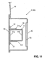
- a reinforcement member 60 comprises upper and lower horizontal face portions 60a, 60b, a side face portion 60c which is provided at inward end portions of the horizontal face portions 60a, 60b, and flange portions 60d, 60e which are provided at outward end portions of the horizontal portions 60a, 60b.
- the reinforcement member 60 preferably substantially has a U-shaped cross section which opens outward.
- the flange portions 60d, 60e are welded to the outside side face portion 5a of the front side frame, so that the reinforcement member 60 forms a closed cross section extending in the vehicle longitudinal direction together with the outside side face portion 5a.
- the inside side face portion 60c is or is to be located at a position which is closer to the inside side face portion 5b of the front side frame 5 than the outside side face portion 5a. Thereby, the side face portion 60c of the reinforcement member 60 contacts the inner face of the inside side face portion 5b of the front side frame 5 as properly soon as possible when the front side frame 5 bends outward at the bend portion T2.
- the reinforcement member 60 is or is to be attached to the outside side face portion 5a of the front side frame 5 so as to form the substantially closed cross section substantially extending in the longitudinal direction together with the outside side face portion 5a, the rigidity of the reinforcement member 60 is increased, so that the amount of energy absorption with the contacting can be further increased.
- a reinforcement member 70 comprises a substantially rectangular pipe member 71 which comprises left and right side face portions 71a, 71b and upper and lower horizontal face portions 71c, 71d and has a closed cross section extending in the vehicle longitudinal direction and a pair of brackets 72, 72 which is fixed to outside portions of the horizontal face portions 71c, 71d.
- the brackets 72, 72 are connected (preferably welded) to the outside side face portion 5a of the front side frame 5.
- the inside side face portion 71b is located at a position which is closer to the inside side face portion 5b of the front side frame 5 than the outside side face portion 5a. Thereby, the side face portion 71b of the reinforcement member 70 contacts the inner face of the inside side face portion 5b of the front side frame 5 as properly soon as possible when the front side frame 5 bends outward at the bend portion T2.
- the reinforcement member 70 is attached to the outside side face portion 5a of the front side frame 5 and singly forms the substantially closed cross section extending in the longitudinal direction, the increase of the amount of energy absorption can be achieved regardless of the shape, thickness or the like of the front side frame 5.
- a reinforcement member 80 comprises a substantially circular or round pipe member 81 which has a substantially closed cross section extending in the vehicle longitudinal direction and a pair of brackets 82, 82 which is or is to be fixed to upper and lower of the circular pipe member 81.
- the brackets 82, 82 are welded to the outside side face portion 5a of the front side frame 5.
- An inside end portion 81a of the circular pipe member 81 is or is to be located at a position which is closer to the inside side face portion 5b of the front side frame 5 than the outside side face portion 5a. Thereby, the inside end portion 81 a of the reinforcement member 80 contacts the inner face of the inside side face portion 5b of the front side frame 5 as properly soon as possible when the front side frame 5 bends outward at the bend portion T2.
- the reinforcement member 80 preferably is attached to the outside side face portion 5a of the front side frame 5 and singly forms the closed cross section extending in the longitudinal direction, the increase of the amount of energy absorption can be achieved regardless of the shape, thickness or the like of the front side frame 5 like the third embodiment.
- the width of a front side frame 5' preferably is set to be narrower than that of the front side frame of the first through fourth embodiments e.g. for the reason of the size of vehicle. Accordingly, the amount of energy absorption by the front side frame 5' itself is relatively small compared to the first through fourth embodiments.
- the fifth embodiment includes some measure against this matter.
- At least one reinforcement member 90 has plural closed cross sections which extend substantially in the vehicle longitudinal direction.
- the reinforcement member 90 comprises an outside face member 91 which is or is to be attached to an outside side face portion 5a' of the front side frame 5' and provided substantially in parallel to this face portion 5a', at least one substantially U-shaped-cross-section member 92 which is or is to be attached to the outside face member 91 and has a face portion 92a which is substantially in parallel to an inside side face portion 5b', and a section-partition member 93 which has a face portion 93a in parallel to the inside side face portion 5b' operative to at least partly partition an inside space formed by these members 91, 92 into two parts in the vehicle width direction.
- the front side frame 5' has its upper and lower horizontal face portions 5c', 5d' like the above-described front side frame 5.
- a bead 5g' is formed at the inner side face portion 5b' likewise.
- the reinforcement member 90 forms two or more closed cross sections together with the front side frame 5' or singly in such a manner that the two or more closed cross sections extend in the vehicle longitudinal direction and at least partly overlap with each other in the vehicle width direction, the amount of energy absorption with the contacting can be further increased. Further, since the two closed cross sections at least partly overlap with each other in the vehicle width direction, the rigidity for the bending in the vehicle width direction is not increased improperly compared to a case in which the two closed cross sections are configured to overlap with each other in the vertical direction.
Description
- The present invention relates to a frame structure for an automotive vehicle, to an automotive vehicle provided therewith and to a method for providing a frame structure for or on a vehicle, and in particular, relates to a structure and method for impact absorption.
- Japanese Patent Laid-Open Publication No.
2003-220977 - Herein, according to the structure disclosed in the above-described patent publication, since the frame member has a closed cross section which extends in the longitudinal direction, the amount of energy absorption may be greater at a bending start compared to a case in which the frame member has no closed cross section. However, the increase degree of this amount of energy absorption tends to reduce considerable after the bending start, so that there is a concern that the impact energy could not be absorbed properly.
- Document
EP 1 149 756 A2 on what base the preambles ofindependent claims 1 and 12 are founded, discloses a body structure of a vehicle having a cabin and front and rear compartments which includes a pair of laterally spaced frame members extending forwardly of the cabin at sides of the front compartment. The side frame members include widthwise rigidity lowering sections, respectively, to allow inward bending of a rear section of each side frame member in a widthwise direction to provide an increased collapsible stroke for thereby effectively absorbing energy in a wide range, typically in a frontal impact. - Document
US 2003/0075951 A1 discloses a body frame structure for vehicle, comprising at least one body frame which includes a brittle section which is formed at a predetermined section in a lengthwise direction of the body frame, wherein the brittle section is more brittle than other sections of the body frame wherein the brittle section is hardened by a hardening treatment so as to become approximately equal to the other sections of the body frame in axial compressive strength. - Document
US 5,984,403 discloses a frame structure for vehicle body with a frame having a box-shaped cross section and a portion bendable when a collision load is applied in a longitudinal direction of the frame in case of a vehicle collision. The frame structure comprises a pair of bead portions arranged in a roughly V shape and formed on a least one of two opposite surfaces of the frame in such a direction that a bending moment generated at that bendable portion of the frame can be cancelled by an additional moment generated by the pair of the bead portions in case of a vehicle collision. - An object of the present invention is to properly increase the amount of energy absorption even after the bending start of the frame member.
- The object is solve according to the present invention by the features of the independent claims. Preferred embodiments of the present invention are subject of the dependent claims.
- According to the present invention, there is provided a frame structure for an automotive vehicle, comprising a hollow frame member provided so as to extend substantially in a vehicle longitudinal direction and connect to a dash panel at a rear end portion thereof, the frame member having both-side side face portions and upper and lower horizontal face portions so as to have a substantially-rectangular cross section, the frame member having a bend portion which is operative to bend toward one side substantially in a vehicle width direction when a longitudinal impact load acts thereon, and at least one reinforcement member provided inside the frame member at a space which includes the bend portion of the frame member in such a manner that the reinforcement member is off an inner face of one of the side face portions of the frame member which is located on a side opposite to the one side toward which the bend portion bends in an initial state and the reinforcement member comes to contact the inner face of the one of the side face portions of the frame member as the frame member bends at the bend portion during an action of the impact load.
- According to the present invention, the reinforcement member provided inside the frame member at the space including the bend portion of the frame member contacts the inner face of the one of the side face portions of the frame member as the frame member bends at the bend portion during the action of the impact load. Thereby, the bending of the frame member can be properly restrained from progressing abruptly after contacting. Further, since the reinforcement member is deformed after the contacting, the amount of energy absorption can be properly increased with the deformation of the reinforcement member.
- According to an embodiment of the present invention, the reinforcement member is configured such that a portion thereof which is operative to come to contact the frame member is located at a position which is closer to the one of the side face portions of the frame member than the other of the side face portions of the frame member. Thereby, the contacting of the reinforcement member and the frame member can be made occur as properly soon as possible. Thus, the amount of energy absorption can be increased further properly.
- According to another embodiment of the present invention, the reinforcement member comprises both-side side face portions and a horizontal face portion which is provided at either a lower side or an upper side between the both-side side face portions thereof so as to have a U-shaped or reverse-U-shaped cross section, and the reinforcement member is configured such that one of the side face portions of the reinforcement member which is located on the one side toward which the bend portion bends is joined to the one of the side face portions of the frame member and the other of the side face portions of the reinforcement member comes to contact the inner face of the one of the side face portions of the frame member as the bend portion bends during the action of the impact load. Thereby, the increase of the energy absorption can be achieved with a simpler structure of the reinforcement member. Further, the one of the side face portions of the reinforcement member may be easily attached to the one of the side face portions of the frame member via welding.
- According to another embodiment of the present invention, the reinforcement member is attached to the one of the side face portions of the frame member in such a manner that a closed cross section is formed together with the one of the side face portions of the frame member. Thereby, the rigidity of the reinforcement member is increased, so that the amount of energy absorption with the contacting can be further increased.
- According to another embodiment of the present invention, the reinforcement member is attached to the one of the side face portions of the frame member in such a manner that a closed cross section is formed therewith singly. Thereby, the increase of the amount of energy absorption can be achieved regardless of the shape, thickness or the like of the frame member.
- According to another embodiment of the present invention, the reinforcement member forms two closed cross sections together with the frame member or singly in such a manner that the two closed cross sections extend in the vehicle longitudinal direction and overlap with each other in the vehicle width direction. Thereby, the amount of energy absorption with the contacting can be further increased. Further, since the two closed cross sections overlap with each other in the vehicle width direction, the rigidity for the bending in the vehicle width direction is not increased improperly compared to a case in which the two closed cross sections are configured to overlap with each other in the vertical direction. Thus, the proper energy absorption can be achieved even in a case in which the frame member has a relatively narrow width.
- According to another embodiment of the present invention, the frame member is comprised of a pair of frame members which are located away from each other in the vehicle width direction, a vehicle constituting member is provided between the pair of frame members, and the pair of frame members have respective bend portions which are operative to bend outward of the vehicle respectively. Thereby, the frame member which has bent does not contact the vehicle constituting member. Thus, the impact energy can be properly absorbed avoiding any contact with the vehicle constituting member provided between the frame members.
- According to another embodiment of the present invention, the bend portion of the frame member comprises a bead which is formed at the one of the side face portions of the frame member so as to extend substantially vertically in such a manner that the bead is recessed toward the one side in the vehicle width direction which is a bending direction of the bend portion. Thereby, the bending point or direction can be stabilized.
- According to another embodiment of the present invention, at least one reinforcement member is provided substantially in the vehicle longitudinal direction in such a manner that a front end portion thereof connects to the frame member at a location which is right behind a rear end of the reinforcement member and a rear end portion thereof connects to a vehicle-body constituting member behind the frame member. Thereby, the rear end portion of the frame member can be reinforced. Further, part of the energy absorption can be performed by the reinforcement member, so that flexibility of setting the longitudinal length of the reinforcement member and the like can be improved.
- According to another embodiment of the present invention, the bend portion of the frame member is comprised of a plurality of portions which have different bending amounts, and the reinforcement member is provided only for one of the portions which has the greatest bending amount. Thereby, the amount of energy absorption can be increased efficiently with restraint of the weight increase caused by the reinforcement member.
- According to the invention, there is further provided an automotive vehicle comprising a frame structure according to the invention or a preferred embodiment thereof.
- According to the invention, there is further provided a method of providing a frame structure for an automotive vehicle, in particular according to the invention or a preferred embodiment thereof, or a method for absorbing energy upon a load acting thereon comprising the steps of:
- providing a hollow frame member so as to extend substantially in a vehicle longitudinal direction and connect to a dash panel at a rear end portion thereof, the frame member having both-side side face portions and upper and lower horizontal face portions so as to have a substantially-rectangular cross section, the frame member having a bend portion which is operative to bend toward one side substantially in a vehicle width direction when a longitudinal impact load acts thereon; and
- providing at least one reinforcement member inside said frame member at a space which includes the bend portion of the frame member in such a manner that the reinforcement member is off an inner face of one of the side face portions of the frame member which is located on a side opposite to said one side toward which the bend portion bends in an initial state and the reinforcement member comes to contact the inner face of the one of the side face portions of the frame member as the frame member bends at the bend portion during an action of the impact load.
- Other features, aspects, and advantages of the present invention will become apparent from the following description which refers to the accompanying drawings. It should be understood that even though embodiments are separately described, single features thereof may be combined to additional embodiments.
-
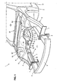
FIG. 1 is a perspective view showing a frame structure of an automotive vehicle according to a first embodiment of the present invention, when viewed from the vehicle front. -
FIG. 2 is a view along an arrow A ofFIG. 1 . -
FIG. 3 is a view along an arrow B ofFIG. 2 . -
FIG. 4 is a sectional view taken along line C-C ofFIG. 2 . -
FIG. 5 is a sectional view taken along line D-D ofFIG. 2 . -
FIG. 6 is an explanatory diagram of an action of bending of a front side frame. -
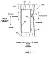
FIG. 7 is a sectional view taken along line E-E ofFIG. 2 at the bending of the front side frame. -
FIG. 8 is a sectional view taken along line C-C ofFIG. 2 at the bending of the front side frame. -
FIG. 9A is a load characteristic diagram andFIG. 9B is an energy-absorption-amount characteristic diagram at the bending of the front side frame. -
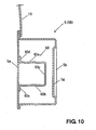
FIG. 10 is a sectional view according to a second embodiment, which corresponds toFIG. 4 . -
FIG. 11 is a sectional view according to a third embodiment, which corresponds toFIG. 4 . -
FIG. 12 is a sectional view according to a fourth embodiment, which corresponds toFIG. 4 . -
FIG. 13 is a sectional view according to a fifth embodiment, which corresponds toFIG. 4 . - Hereinafter, a front body structure for an automotive vehicle according to preferred embodiments of the present invention will be described.
- As shown in
FIGS. 1 and2 , adash panel 2 which at least partly partitions an engine room Z1 with an engine EG from a vehicle compartment Z2 in which a passenger is present is or is to be provided at a front portion of an automotive vehicle 1 of the present embodiment. - One or more, preferably a pair of hinge pillars 3 (only one of them is illustrated) which extends substantially vertically and pivotally supports front doors (not illustrated) is provided at or near both-side end portions of the
dash panel 2. - One or more, preferably a pair of apron reinforcements 4, 4 substantially extends forward from upper end portions of the
hinge pillars 3. One or more, preferably a pair of front side frames 5, 5 substantially extends in a vehicle longitudinal direction preferably substantially in parallel to the apron reinforcements 4, 4 in a plan view so as to be away from each other substantially in a vehicle width direction. Awheel house 6 for a front wheel is at least partly provided between the apron reinforcement 4 and thefront side frame 5 in the vehicle width direction. -
Plates bumper reinforcement 9 is attached to the right and leftplates more crush cans crush cans - A lower portion of the
dash panel 2 curves substantially rearward, and its lower end portion connects to a front end portion of afloor panel 10. Atunnel portion 11 is provided at or near the lower portion of thedash panel 2 and thefloor panel 10 so as to extend substantially longitudinally at the intermediate or central portion in the vehicle width direction and project upward. - A rear portion of the
front side frame 5 curves substantially downward beside thewheel house 6, and its lower end portion connects to a front end portion of afloor frame 12 which substantially extends in the vehicle longitudinal direction below the floor panel 10 (FIG. 2 ). Thefloor frame 12, which preferably has a U-shaped cross section, forms a substantially closed cross section which substantially extends in the vehicle longitudinal direction together with thefloor panel 10. - A
side sill 13 extends rearward from a lower end portion of thefront hinge pillar 3. Theside sill 13 has a substantially closed cross section which substantially extends in the vehicle longitudinal direction. - A lower
dash cross member 14 and an upperdash cross member 16 are respectively provided at or near the lower portion and the upper portion of thedash panel 2 so as to interconnect the right and lefthinge pillars cross members dash panel 2. - The
wheel house 6 is formed by making the rear portion of anapron panel 19 project substantially upward. Theapron panel 19 connects to the apron reinforcement 4 at its outer end, and it connects to thefront side frame 5 at its inner end. At an upper end of thewheel house 6 is provided asuspension tower portion 6a which is formed by theapron panel 19 projecting upward. - A
cowl portion 20 which has a substantially closed cross section extending in the vehicle width direction is formed at the upper portion of thedash panel 2. The apron reinforcement 4 preferably substantially has a substantially-rectangular closed cross section which extends in the vehicle longitudinal direction. - In the present embodiment, as shown in
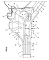
FIG. 3 , at least onereinforcement member 30 is provided at a back face of theapron panel 19 at thewheel house 6 which is on an opposite side to the engine room Z1. - The
reinforcement member 30 connects to an outer member 51 (facing toward the inside of the wheel house 6) of thefront side frame 5 at itsfront end portion 30a, and substantially extends obliquely rearward and upward. A rear side portion of thereinforcement member 30 preferably branches to a rear portion and an upper portion. Anend portion 30b of the rear portion connects to the dash panel 2 (vehicle body member), and anend portion 30c of the upper portion connects to an inner face of atop portion 6a' of thesuspension tower portion 6a. Thereinforcement member 30 preferably has a substantially U-shaped cross section which opens toward the inside of the vehicle, and forms a closed cross section along with theapron panel 19. - Further, as apparent from
FIGS. 1 and2 , asecond reinforcement member 35 preferably with a U-shaped cross section is provided so as to interconnect the rear portion of thefront side frame 5 and the lowerdash cross member 14. Further, as shown inFIG. 6 which will be described later, a front end portion of atunnel frame 36 which extends substantially in the vehicle longitudinal direction along thetunnel portion 11 connects to a rear end portion of thesecond reinforcement member 35. - Hereinafter, the structure of the
front side frame 5 will be described specifically. - The
front side frame 5 is, as shown inFIG. 4 , formed by joining or connecting anoutside member 41 which is of a flat plate shape and located outward of the vehicle to aninside member 42 which preferably has a U-shaped cross section and is located inward of the vehicle. Thus, thefront side frame 5 has left and rightside face portions horizontal face portions - Herein, the
front side frame 5 comprises afront portion 5A in front of thesuspension tower portion 6a and arear portion 5B in back of thesuspension tower portion 6a as apparent fromFIGS. 1 and2 . The front andrear portions front portion 5A may be made from a material, such as a high-tension material, which can maintain a specified (predetermined or predeterminable) rigidity at a normal condition and collapse like a bellows shape when receiving an impact load acting. Meanwhile, therear portion 5B may be made from a thicker material so that the load resistance of thisportion 5B can be greater than that of thefront portion 5A. That is, therear portion 5B does not collapse so easily compared to thefront portion 5A. - Further, at an
outside member 41A and aninside member 42A of thefront portion 5A are respectively formed one ormore beads FIGS. 1 ,2 and5 . Thesebeads front portion 5A of thefront side frame 5 collapses in the vehicle longitudinal direction. - As shown in
FIGS. 1 and4 , the width (length in the vehicle width direction) of the rear portion of thefront portion 5A of thefront side frame 5 preferably becomes narrow gradually. Accordingly, when the impact load acts on thefront side frame 5 from the vehicle front, this rear portion of thefront portion 5A tends to bend outward (toward the vehicle outside) easily. Thus, a bend portion T1 which is operative to bend outward is provided at the rear portion of thefront portion 5A of thefront side frame 5 as shown inFIGS. 2 and6 . - Further, as shown in
FIG. 2 , at least onebead 5g which extends substantially vertically is formed at the insideside face portion 5b of thefront side frame 5 beside thesuspension tower portion 6a. Thebead 5g is recessed outward (toward the vehicle outside) as shown inFIG. 4 , so that when the impact load acts on thefront side frame 5 from the vehicle front, thefront side frame 5 bends substantially outward with a bending point of thebead 5g. Thus, the bend portion T2 is formed or defined by thebead 5g. - Further, as shown in
FIGS. 2 and3 , at least onebead 5h which substantially extends vertically is formed at the outsideside face portion 5a of thefront side frame 5 at acurve portion 5w. Thebead 5h is substantially recessed inward (toward the vehicle inside) so that when the impact load acts on thefront side frame 5 from the vehicle front, thefront side frame 5 bends substantially outward with a bending point of thebead 5h. Thus, the bend portion T3 is formed or defined by thebead 5h. - According to the above-described structure, when the impact load is inputted to the
bumper reinforcement 9 at a frontal collision or the like of the automotive vehicle 1, the impact load acts on the front side frames 5, 5 substantially via thecrush cans - Then, each crush can 8 collapses substantially in the vehicle longitudinal direction as shown in 6A, which shows its initial state, and 6B. As described above, the front portion (longitudinal positions P1-P2) of the
front side frame 5 which is in front of thesuspension tower portion 6a collapses substantially in the longitudinal direction, and thefront side frame 5 bends substantially outward at the bend portions T1, T2 and T3 (longitudinal positions P2, P3 and P4). Specifically, a specified (predetermined or predeterminable) portion of thefront side frame 5 between the longitudinal positions P2 and P4 bends substantially outward at the bend portion T2 (longitudinal position P3). Part of the impact load is absorbed by this collapsing and bending. Herein, the longitudinal position P1 is a position of the front end of thefront side frame 5, the longitudinal position P2 is a position in which the width of thefront side frame 5 reduces (bend portion T1), the longitudinal position P3 is a position of thebead 5g (bend portion T2), the longitudinal position P4 is a position of thebead 5h (bend portion T3), and the longitudinal position P5 is a position of the rear end of thefront side frame 5. - Further, since the
reinforcement member 30 is provided, part of the impact load is dispersed to thedash panel 2 and thetop portion 6a' of thesuspension tower 6a. As a result, it is prevented that theframe 5 is deformed vertically or broken at thecurve portion 5w. - Further, since the
second reinforcement member 35 is provided, it is prevented that thefront side frame 5 bends inward at the bend portion T3, so that thefront side frame 5 can be made bend outward surely. - Also, since the left and right front side frames 5, 5 bend outward respectively, the
frames right frames - Also, since the bend portion T2 is comprised of the
bead 5g which is formed at theinside face portion 5b of thefront side frame 5 so as to extend vertically in such a manner that thebead 5g is recessed outward, the bending point and direction is stabilized. - Herein, in the present embodiment, as shown in
FIG. 2 , at least onereinforcement member 50 is provided inside thefront side frame 5 at a space which includes (or at least partly corresponds to) the above-described bend portion T2 of thefront side frame 5. Thereinforcement member 50 preferably is provided only for the bend portion T2 which has the greatest bending amount among the bend portions T1-T3. - The
reinforcement member 50 comprises, as shown inFIG. 4 , left and rightside face portions horizontal face portion 50c which is provided at a lower side between theside face portions - The outside
side face portion 50a of thereinforcement member 50 is joined to theoutside face portion 5a of thefront side frame 5. Meanwhile, the insideside face portion 50b is located at a position which is closer to the insideside face portion 5b of thefront side frame 5 than the outsideside face portion 5a. - Herein, when the
front side frame 5 bends outward at the bend portion T2, as shown inFIG. 7 , a force of an extension direction in the vehicle longitudinal direction is applied to the outsideside face portion 5a and a force of a compression direction is applied to the insideside face portion 5b. Since thereinforcement member 50 is provided at the outsideside face portion 5a, the stress concentrates in the area around thebead 5g of the insideside face portion 5b. As a result, as shown inFIG. 8 as well, thehorizontal face portions bead 5g comes to contact the insideside face portion 50b of thereinforcement member 50. - As described above, according to the present embodiment, since the
reinforcement member 50 is provided inside thefront side frame 5 at the space which includes (or at least partly corresponds to) the bend portion T2 in such a manner that thereinforcement member 50 preferably comes to contact the inner face of theside face portion 5b of thefront side frame 5 during the bending, the bending of thefront side frame 5 can be properly restrained from progressing abruptly after contacting. Further, since thereinforcement member 50 is deformed after the contacting, the deformation load can be increased as shown inFIG. 9A and the amount of energy absorption can be properly increased as shown inFIG. 9B , compared to a case in which no reinforcement member is provided. - Further, since the inside
side face portion 50b preferably is or is to be located at the position which is closer to the insideside face portion 5b of thefront side frame 5 than the outsideside face portion 5b, the contacting of thereinforcement member 50 and theframe 5 can be made occur as properly soon as possible. Thus, the amount of energy absorption can be increased further properly. - Further, since the
reinforcement member 50 is configured as described above, the increase of the energy absorption can be achieved with a simpler structure of thereinforcement member 50. Further, the outsideside face portion 50a of thereinforcement member 50 may be easily attached to the outsideside face portion 5a of theframe 5 via welding using guns G1, G2. - Also, since the
reinforcement member 30 preferably is provided substantially in the vehicle longitudinal direction in such a manner that its front end portion connects to thefront side frame 5 at the location which is right behind (or adjacent to) the rear end of thereinforcement member 50 and its rear end portion connects to thedash panel 2 and thesuspension tower portion 6a behind theframe 5, the rear end portion of theframe 5 can be reinforced. Further, part of the energy absorption can be performed by the reinforcement member, so that flexibility of setting the longitudinal length of thereinforcement member 50 and the like can be improved. - Further, since the
reinforcement member 50 preferably is provided only for the bend portion T2 which has the greatest bending amount among the bend portions T1-T3, the amount of energy absorption can be increased efficiently restraining the weight increase by thereinforcement member 50. - While the
reinforcement member 50 comprises the left and rightside face portions horizontal face portion 50c so as to have the U-shaped cross section in the present embodiment, it may be configured to have the both side face portions and an upper horizontal face portion so as to have a reverse-U-shaped cross section. - Accordingly, a
reinforcement member 50 is provided inside aframe member 5 at a space which includes a bend portion T2 operative to bend upon a substantially longitudinal force acting thereon (e.g. due to a head-on collision) in such a manner that thereinforcement member 50 comes to substantially contact an inner face of an insideside face portion 5b of theframe member 5 as theframe member 5 bends at the bend portion T2. Accordingly, the amount of energy absorption even after the bending start of the frame member can be properly increased. - Hereinafter, other embodiments will be described. Herein, the structure except the reinforcement member is similar or the same as the above-described first embodiment. The similar or same structure is denoted by the same reference characters, and their descriptions will be omitted here.
- In a second embodiment, as shown in
FIG. 10 , areinforcement member 60 comprises upper and lowerhorizontal face portions side face portion 60c which is provided at inward end portions of thehorizontal face portions flange portions horizontal portions reinforcement member 60 preferably substantially has a U-shaped cross section which opens outward. Theflange portions side face portion 5a of the front side frame, so that thereinforcement member 60 forms a closed cross section extending in the vehicle longitudinal direction together with the outsideside face portion 5a. - The inside
side face portion 60c is or is to be located at a position which is closer to the insideside face portion 5b of thefront side frame 5 than the outsideside face portion 5a. Thereby, theside face portion 60c of thereinforcement member 60 contacts the inner face of the insideside face portion 5b of thefront side frame 5 as properly soon as possible when thefront side frame 5 bends outward at the bend portion T2. - According to the second embodiment, since the
reinforcement member 60 is or is to be attached to the outsideside face portion 5a of thefront side frame 5 so as to form the substantially closed cross section substantially extending in the longitudinal direction together with the outsideside face portion 5a, the rigidity of thereinforcement member 60 is increased, so that the amount of energy absorption with the contacting can be further increased. - A third embodiment will be described.
- In the third embodiment, as shown in
FIG. 11 , areinforcement member 70 comprises a substantially rectangular pipe member 71 which comprises left and rightside face portions horizontal face portions 71c, 71d and has a closed cross section extending in the vehicle longitudinal direction and a pair ofbrackets horizontal face portions 71c, 71d. Thebrackets side face portion 5a of thefront side frame 5. - The inside
side face portion 71b is located at a position which is closer to the insideside face portion 5b of thefront side frame 5 than the outsideside face portion 5a. Thereby, theside face portion 71b of thereinforcement member 70 contacts the inner face of the insideside face portion 5b of thefront side frame 5 as properly soon as possible when thefront side frame 5 bends outward at the bend portion T2. - According to the third embodiment, since the
reinforcement member 70 is attached to the outsideside face portion 5a of thefront side frame 5 and singly forms the substantially closed cross section extending in the longitudinal direction, the increase of the amount of energy absorption can be achieved regardless of the shape, thickness or the like of thefront side frame 5. - A fourth embodiment will be described.
- In the fourth embodiment, as shown in
FIG. 12 , areinforcement member 80 comprises a substantially circular orround pipe member 81 which has a substantially closed cross section extending in the vehicle longitudinal direction and a pair ofbrackets circular pipe member 81. Thebrackets side face portion 5a of thefront side frame 5. - An
inside end portion 81a of thecircular pipe member 81 is or is to be located at a position which is closer to the insideside face portion 5b of thefront side frame 5 than the outsideside face portion 5a. Thereby, theinside end portion 81 a of thereinforcement member 80 contacts the inner face of the insideside face portion 5b of thefront side frame 5 as properly soon as possible when thefront side frame 5 bends outward at the bend portion T2. - According to the fourth embodiment, since the
reinforcement member 80 preferably is attached to the outsideside face portion 5a of thefront side frame 5 and singly forms the closed cross section extending in the longitudinal direction, the increase of the amount of energy absorption can be achieved regardless of the shape, thickness or the like of thefront side frame 5 like the third embodiment. - A fifth embodiment will be described.
- In the fifth embodiment, as shown in
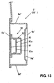
FIG. 13 , the width of a front side frame 5' preferably is set to be narrower than that of the front side frame of the first through fourth embodiments e.g. for the reason of the size of vehicle. Accordingly, the amount of energy absorption by the front side frame 5' itself is relatively small compared to the first through fourth embodiments. The fifth embodiment includes some measure against this matter. - At least one
reinforcement member 90 has plural closed cross sections which extend substantially in the vehicle longitudinal direction. Specifically, thereinforcement member 90 comprises anoutside face member 91 which is or is to be attached to an outsideside face portion 5a' of the front side frame 5' and provided substantially in parallel to thisface portion 5a', at least one substantially U-shaped-cross-section member 92 which is or is to be attached to theoutside face member 91 and has aface portion 92a which is substantially in parallel to an insideside face portion 5b', and a section-partition member 93 which has aface portion 93a in parallel to the insideside face portion 5b' operative to at least partly partition an inside space formed by thesemembers 91, 92 into two parts in the vehicle width direction. Herein, the front side frame 5' has its upper and lowerhorizontal face portions 5c', 5d' like the above-describedfront side frame 5. Also, abead 5g' is formed at the innerside face portion 5b' likewise. - According to the fifth embodiment, since the
reinforcement member 90 forms two or more closed cross sections together with the front side frame 5' or singly in such a manner that the two or more closed cross sections extend in the vehicle longitudinal direction and at least partly overlap with each other in the vehicle width direction, the amount of energy absorption with the contacting can be further increased. Further, since the two closed cross sections at least partly overlap with each other in the vehicle width direction, the rigidity for the bending in the vehicle width direction is not increased improperly compared to a case in which the two closed cross sections are configured to overlap with each other in the vertical direction.
Claims (12)
- A frame structure for an automotive vehicle (1), comprising:a hollow frame member (5; 5') provided so as to extend substantially in a vehicle longitudinal direction and connect to a dash panel (2) at a rear end portion thereof, the frame member (5; 5') having both-side side face portions (5a, 5b; 5a', 5b') and upper and lower horizontal face portions (5c, 5d; 5c', 5d') so as to have a substantially-rectangular cross section, the frame member (5; 5') having a bend portion (T2) which is operative to bend toward one side substantially in a vehicle width direction when a longitudinal impact load acts thereon;characterized by at least one reinforcement member (50; 60; 70; 80; 90) provided inside said frame member (5; 5') at a space which includes the bend portion (T2) of the frame member (5; 5') in such a manner that the reinforcement member (50; 60; 70; 80; 90) is off an inner face of one of the side face portions (5b; 5b') of the frame member (5; 5') which is located on a side opposite to said one side toward which the bend portion bends in an initial state and the reinforcement member (50; 60; 70; 80; 90) comes to contact the inner face of the one of the side face portions (5b; 5b') of the frame member (5; 5') as the frame member (5; 5') bends at the bend portion (T2) during an action of the impact load.
- The frame structure for an automotive vehicle (1) of claim 1, wherein said reinforcement member (50; 60; 70; 80; 90) is configured such that a portion thereof (50b; 60c; 71b; 81a; 92b) which is operative to come to contact said frame member (5; 5') is located at a position which is closer to said one of the side face portions (5b; 5b') of the frame member (5; 5') than the other of the side face portions (5a; 5a') of the frame member (5; 5').
- The frame structure for an automotive vehicle (1) of any one of the preceding claims, wherein said reinforcement member (50) comprises both-side side face portions (50a, 50b) and a horizontal face portion (50c) which is provided at either a lower side or an upper side between the both-side side face portions (50a, 50b) thereof so as to have a U-shaped or reverse-U-shaped cross section, and the reinforcement member (50) is configured such that one of the side face portions (50a) of the reinforcement member (50) which is located on said one side toward which the bend portion (T2) bends is joined to said one of the side face portions (5a) of the frame member (50) and the other of the side face portions (50b) of the reinforcement member (50) comes to contact said inner face of the one of the side face portions (5b) of the frame member (5) as the bend portion bends during the action of the impact load.
- The frame structure for an automotive vehicle (1) of any one of the preceding claims, wherein said reinforcement member (60) is attached to said one of the side face portions (5a) of the frame member (5) in such a manner that a closed cross section is formed together with the one of the side face portions (5a) of the frame member (5).
- The frame structure for an automotive vehicle (1) of any one of the preceding claims, wherein said reinforcement member (70; 80; 90) is attached to said one of the side face portions (5a; 5a') of the frame member (5; 5') in such a manner that a closed cross section is formed therewith singly.
- The frame structure for an automotive vehicle (1) of any one of the preceding claims, wherein said reinforcement member (90) forms two closed cross sections together with the frame member (5') or singly in such a manner that the two closed cross sections extend in the vehicle longitudinal direction and at least partly overlap with each other in the vehicle width direction.
- The frame structure for an automotive vehicle (1) of any one of the preceding claims, wherein said frame member (5; 5') is comprised of a pair of frame members which are located away from each other in the vehicle width direction, a vehicle constituting member (EG) is provided between the pair of frame members (5, 5; 5', 5'), and the pair of frame members have respective bend portions (T2) which are operative to bend outward of the vehicle respectively.
- The frame structure for an automotive vehicle (1) of anyone of the preceding claims, wherein said bend portion (T2) of the frame member (5; 5') comprises a bead (5g; 5g') which is formed at said one of the side face portions (5b; 5b') of the frame member (5; 5') so as to extend substantially vertically in such a manner that the bead (5g; 5g') is recessed toward said one side in the vehicle width direction which is a bending direction of the bend portion (T2).
- The frame structure for an automotive vehicle (1) of claim 8, wherein at least one reinforcement member (30) is provided substantially in the vehicle longitudinal direction in such a manner that a front end portion thereof connects to said frame member (5; 5') at a location which is right behind a rear end of said reinforcement member and a rear end portion thereof connects to a vehicle-body constituting member (2, 6a) behind the frame member (5; 5').
- The frame structure for an automotive vehicle (1) of any one of claims 1 through 9, wherein said bend portion of the frame member (5; 5') is comprised of a plurality of portions (T1, T2, T3) which have different bending amounts, and said reinforcement member (50; 60; 70; 80; 90) is provided only for one of the portions (T2) which has the greatest bending amount.
- An automotive vehicle (1) comprising a frame structure according to any one of the preceding claims.
- A method of providing a frame structure for an automotive vehicle (1), comprising the steps of:providing a hollow frame member (5; 5') so as to extend substantially in a vehicle longitudinal direction and connect to a dash panel (2) at a rear end portion thereof, the frame member (5; 5') having both-side side face portions (5a, 5b; 5a', 5b') and upper and lower horizontal face portions (5c, 5d; 5c', 5d') so as to have a substantially-rectangular cross section, the frame member (5; 5') having a bend portion (T2) which is operative to bend toward one side substantially in a vehicle width direction when a longitudinal impact load acts thereon;characterized by providing at least one reinforcement member (50; 60; 70; 80; 90) inside said frame member (5; 5') at a space which includes the bend portion (T2) of the frame member (5; 5') in such a manner that the reinforcement member (50; 60; 70; 80; 90) is off an inner face of one of the side face portions (5b; 5b') of the frame member (5; 5') which is located on a side opposite to said one side toward which the bend portion bends in an initial state and the reinforcement member (50; 60; 70; 80; 90) comes to contact the inner face of the one of the side face portions (5b; 5b') of the frame member (5; 5') as the frame member (5; 5') bends at the bend portion (T2) during an action of the impact load.
Applications Claiming Priority (1)
| Application Number | Priority Date | Filing Date | Title |
|---|---|---|---|
| JP2008085191A JP2009234495A (en) | 2008-03-28 | 2008-03-28 | Frame structure of automobile |
Publications (2)
| Publication Number | Publication Date |
|---|---|
| EP2105372A1 EP2105372A1 (en) | 2009-09-30 |
| EP2105372B1 true EP2105372B1 (en) | 2011-01-05 |
Family
ID=40666792
Family Applications (1)
| Application Number | Title | Priority Date | Filing Date |
|---|---|---|---|
| EP09003297A Expired - Fee Related EP2105372B1 (en) | 2008-03-28 | 2009-03-06 | Frame structure for an automotive vehicle, automotive vehicle provided therewith and method for providing a frame structure |
Country Status (4)
| Country | Link |
|---|---|
| US (1) | US20090243336A1 (en) |
| EP (1) | EP2105372B1 (en) |
| JP (1) | JP2009234495A (en) |
| DE (1) | DE602009000511D1 (en) |
Families Citing this family (33)
| Publication number | Priority date | Publication date | Assignee | Title |
|---|---|---|---|---|
| JP5029328B2 (en) * | 2007-12-05 | 2012-09-19 | マツダ株式会社 | Front body structure of automobile |
| JP5504820B2 (en) | 2009-10-26 | 2014-05-28 | マツダ株式会社 | Front body structure of the vehicle |
| JP5264699B2 (en) * | 2009-12-28 | 2013-08-14 | 本田技研工業株式会社 | Body front structure |
| KR101149737B1 (en) | 2010-05-04 | 2012-06-01 | 주식회사 성우하이텍 | Reinforcement Unit of Front side member |
| US8485591B2 (en) | 2010-05-10 | 2013-07-16 | Honda Motor Co., Ltd. | Front vehicle body structure |
| JP5560329B2 (en) * | 2010-06-10 | 2014-07-23 | 本田技研工業株式会社 | Body front structure |
| EP2428432B1 (en) * | 2010-09-14 | 2014-05-14 | Honda Motor Co., Ltd. | Front side vehicle body structure |
| WO2012102192A1 (en) | 2011-01-26 | 2012-08-02 | 本田技研工業株式会社 | Structure for front of vehicle body |
| JP5585480B2 (en) * | 2011-02-10 | 2014-09-10 | マツダ株式会社 | Body front structure |
| CN102229348B (en) * | 2011-02-12 | 2012-12-19 | 广州汽车集团股份有限公司 | Front longitudinal beam and geometric energy absorbing control structure as well as automobile and method for providing geometric energy absorbing control structure |
| US8398153B1 (en) * | 2011-11-03 | 2013-03-19 | GM Global Technology Operations LLC | Impact deflector for vehicle frame |
| DE102012111671A1 (en) * | 2012-11-30 | 2014-06-05 | Dr. Ing. H.C. F. Porsche Aktiengesellschaft | Reinforcement carrier for installation in longitudinal beam of front end of motor vehicle, is formed as square tube, and has corrugation at its front end area, where corrugation bates side wall of square tube |
| US8876194B2 (en) * | 2013-03-26 | 2014-11-04 | Nissan North America, Inc. | Vehicle front body structure |
| JP5835284B2 (en) * | 2013-07-09 | 2015-12-24 | トヨタ自動車株式会社 | Body front structure |
| JP6206302B2 (en) * | 2014-04-07 | 2017-10-04 | マツダ株式会社 | Vehicle frame structure |
| JP5999134B2 (en) * | 2014-04-25 | 2016-09-28 | トヨタ自動車株式会社 | Vehicle front structure |
| JP6206330B2 (en) * | 2014-06-02 | 2017-10-04 | マツダ株式会社 | Vehicle frame structure |
| JP6206331B2 (en) * | 2014-06-02 | 2017-10-04 | マツダ株式会社 | Vehicle frame structure |
| JP6187771B2 (en) * | 2014-07-31 | 2017-08-30 | マツダ株式会社 | Front body structure of the vehicle |
| JP6300024B2 (en) * | 2014-08-01 | 2018-03-28 | マツダ株式会社 | Front body structure of the vehicle |
| EP3197750B1 (en) * | 2014-09-22 | 2020-05-06 | Arcelormittal | Vehicle front body structure |
| KR101619270B1 (en) * | 2014-10-17 | 2016-05-10 | 현대자동차 주식회사 | Connection structure of a vehicle |
| US9266567B1 (en) * | 2014-10-21 | 2016-02-23 | Toyota Motor Engineering & Manufacturing North America, Inc. | Vehicles having a dash panel reinforcement gusset |
| JP6107850B2 (en) * | 2015-02-27 | 2017-04-05 | マツダ株式会社 | Vehicle frame structure |
| US9714053B2 (en) * | 2015-03-30 | 2017-07-25 | Toyota Jidosha Kabushiki Kaisha | Connecting structure of front apron and cowl |
| US10112563B2 (en) * | 2015-06-30 | 2018-10-30 | Faraday & Future Inc. | Tapered crush can |
| US10300948B2 (en) | 2015-10-30 | 2019-05-28 | Faraday&Future Inc. | Webbing devices for an underbody of a motor vehicle |
| US10131381B2 (en) | 2015-06-30 | 2018-11-20 | Faraday & Future Inc. | Joint for an underbody of a motor vehicle |
| KR101724879B1 (en) | 2015-07-24 | 2017-04-10 | 현대자동차주식회사 | Front body structure and method for producing the same |
| JP6284056B1 (en) * | 2016-09-13 | 2018-02-28 | マツダ株式会社 | Vehicle frame structure |
| JP6569702B2 (en) * | 2017-06-19 | 2019-09-04 | マツダ株式会社 | Front body structure of automobile |
| KR20210057620A (en) * | 2019-11-12 | 2021-05-21 | 현대자동차주식회사 | Vehicle front structure |
| JP7294765B2 (en) * | 2020-11-04 | 2023-06-20 | ダイハツ工業株式会社 | energy absorbing structure |
Family Cites Families (20)
| Publication number | Priority date | Publication date | Assignee | Title |
|---|---|---|---|---|
| SE500174C2 (en) * | 1992-09-11 | 1994-05-02 | Saab Automobile | Threshold reinforcement for reducing floor penetration in offset collisions with passenger cars |
| AU705222B2 (en) * | 1996-02-09 | 1999-05-20 | Toyota Jidosha Kabushiki Kaisha | Front structure of car body, and method of absorbing impact by means of the front structure |
| JP3394142B2 (en) * | 1996-10-25 | 2003-04-07 | 富士重工業株式会社 | Frame structure of vehicle body |
| JP3738508B2 (en) * | 1996-12-13 | 2006-01-25 | 日産自動車株式会社 | Body front frame structure |
| KR100333889B1 (en) * | 1999-12-21 | 2002-04-25 | 류정열 | Reinforcement structure having a member for reinforcing a frame for a motor vehicle |
| US6655728B2 (en) | 2000-04-25 | 2003-12-02 | Nissan Motor Co., Ltd. | Body structure of vehicle |
| KR100362719B1 (en) * | 2000-09-04 | 2002-11-29 | 기아자동차주식회사 | front frame reinforcement structure of car |
| DE10117010A1 (en) * | 2001-04-05 | 2002-10-10 | Daimler Chrysler Ag | Body frame for motor vehicles, esp. cars has two side pillars, roof, seat, and bridge struts to form closed support structure for increased side impact protection |
| KR100412829B1 (en) * | 2001-07-03 | 2003-12-31 | 현대자동차주식회사 | an engine mounting structure on a front side member of vehicles |
| JP4576780B2 (en) * | 2001-09-21 | 2010-11-10 | マツダ株式会社 | Body frame structure and method for manufacturing body frame |
| JP2003312534A (en) * | 2002-04-23 | 2003-11-06 | Nissan Motor Co Ltd | Reinforcement structure of vehicle body skeleton frame |
| JP3882629B2 (en) * | 2002-01-31 | 2007-02-21 | 日産自動車株式会社 | Shock absorption structure for automobiles |
| JP4123021B2 (en) * | 2003-03-17 | 2008-07-23 | 三菱自動車工業株式会社 | Car side members |
| JP3852445B2 (en) * | 2004-01-13 | 2006-11-29 | 日産自動車株式会社 | Impact energy absorption structure of member members |
| JP3988745B2 (en) * | 2004-05-06 | 2007-10-10 | 日産自動車株式会社 | Body floor structure |
| JP2005329789A (en) * | 2004-05-19 | 2005-12-02 | Nissan Motor Co Ltd | Reinforcement structure of member of vehicle body front part |
| JP2005335509A (en) * | 2004-05-26 | 2005-12-08 | Toyota Motor Corp | Vehicular front body structure |
| US7185945B2 (en) * | 2004-08-06 | 2007-03-06 | General Motors Corporation | Structural assembly for vehicles |
| JP4359264B2 (en) * | 2005-06-03 | 2009-11-04 | 本田技研工業株式会社 | Car seat mounting structure |
| JP2006321490A (en) * | 2006-09-11 | 2006-11-30 | Nissan Motor Co Ltd | Reinforcing structure of vehicle body skeleton frame |
-
2008
- 2008-03-28 JP JP2008085191A patent/JP2009234495A/en active Pending
-
2009
- 2009-02-20 US US12/389,879 patent/US20090243336A1/en not_active Abandoned
- 2009-03-06 DE DE602009000511T patent/DE602009000511D1/en active Active
- 2009-03-06 EP EP09003297A patent/EP2105372B1/en not_active Expired - Fee Related
Also Published As
| Publication number | Publication date |
|---|---|
| DE602009000511D1 (en) | 2011-02-17 |
| EP2105372A1 (en) | 2009-09-30 |
| JP2009234495A (en) | 2009-10-15 |
| US20090243336A1 (en) | 2009-10-01 |
Similar Documents
| Publication | Publication Date | Title |
|---|---|---|
| EP2105372B1 (en) | Frame structure for an automotive vehicle, automotive vehicle provided therewith and method for providing a frame structure | |
| EP1125829B1 (en) | Vehicle structure with load transmission elements | |
| US8789875B2 (en) | Vehicle body structure and method of manufacturing vehicle body | |
| JP4286884B2 (en) | Auto body structure | |
| US7331626B2 (en) | Vehicle body structure reinforced against side impact | |
| JP4384206B2 (en) | Auto body structure | |
| US9616935B2 (en) | Vehicle structures and methods of assembling the same | |
| JP6235628B2 (en) | Auto body structure | |
| US8814248B2 (en) | Motor vehicle body with reinforcing structure | |
| JP4636799B2 (en) | Support structure made of hollow steel long section material for automobile | |
| EP2420432B1 (en) | Side vehicle body structure | |
| JP6369550B2 (en) | Automotive parts | |
| CN107922015B (en) | Frame structure of vehicle | |
| CN107074288B (en) | Vehicle front body structure | |
| JP2007038839A (en) | Rear part car body structure for vehicle | |
| JP2005532207A5 (en) | ||
| US8491049B2 (en) | Frontal structure of vehicle | |
| JP2010006154A (en) | Vehicle body structure of automobile | |
| CN113165697B (en) | Front cabin structure assembly for automobile body | |
| KR102575185B1 (en) | Vehicle Body Structure | |
| JP2007126093A (en) | Vehicle frame structure | |
| US9919743B2 (en) | Front end of a motor vehicle | |
| JP5896827B2 (en) | Auto body frame structure | |
| US7083223B2 (en) | Vehicle cab | |
| US10427723B2 (en) | Motor vehicle |
Legal Events
| Date | Code | Title | Description |
|---|---|---|---|
| PUAI | Public reference made under article 153(3) epc to a published international application that has entered the european phase |
Free format text: ORIGINAL CODE: 0009012 |
|
| AK | Designated contracting states |
Kind code of ref document: A1 Designated state(s): AT BE BG CH CY CZ DE DK EE ES FI FR GB GR HR HU IE IS IT LI LT LU LV MC MK MT NL NO PL PT RO SE SI SK TR |
|
| AX | Request for extension of the european patent |
Extension state: AL BA RS |
|
| 17P | Request for examination filed |
Effective date: 20091112 |
|
| 17Q | First examination report despatched |
Effective date: 20091207 |
|
| AKX | Designation fees paid |
Designated state(s): DE |
|
| GRAP | Despatch of communication of intention to grant a patent |
Free format text: ORIGINAL CODE: EPIDOSNIGR1 |
|
| GRAS | Grant fee paid |
Free format text: ORIGINAL CODE: EPIDOSNIGR3 |
|
| GRAA | (expected) grant |
Free format text: ORIGINAL CODE: 0009210 |
|
| AK | Designated contracting states |
Kind code of ref document: B1 Designated state(s): DE |
|
| REF | Corresponds to: |
Ref document number: 602009000511 Country of ref document: DE Date of ref document: 20110217 Kind code of ref document: P |
|
| REG | Reference to a national code |
Ref country code: DE Ref legal event code: R096 Ref document number: 602009000511 Country of ref document: DE Effective date: 20110217 |
|
| REG | Reference to a national code |
Ref country code: DE Ref legal event code: R084 Ref document number: 602009000511 Country of ref document: DE |
|
| REG | Reference to a national code |
Ref country code: DE Ref legal event code: R084 Ref document number: 602009000511 Country of ref document: DE Effective date: 20110831 |
|
| PLBE | No opposition filed within time limit |
Free format text: ORIGINAL CODE: 0009261 |
|
| STAA | Information on the status of an ep patent application or granted ep patent |
Free format text: STATUS: NO OPPOSITION FILED WITHIN TIME LIMIT |
|
| 26N | No opposition filed |
Effective date: 20111006 |
|
| REG | Reference to a national code |
Ref country code: DE Ref legal event code: R097 Ref document number: 602009000511 Country of ref document: DE Effective date: 20111006 |
|
| PGFP | Annual fee paid to national office [announced via postgrant information from national office to epo] |
Ref country code: DE Payment date: 20190219 Year of fee payment: 11 |
|
| REG | Reference to a national code |
Ref country code: DE Ref legal event code: R119 Ref document number: 602009000511 Country of ref document: DE |
|
| PG25 | Lapsed in a contracting state [announced via postgrant information from national office to epo] |
Ref country code: DE Free format text: LAPSE BECAUSE OF NON-PAYMENT OF DUE FEES Effective date: 20201001 |