EP1125501B1 - Vorrichtung zum Spalten von Schlachttierkörpern, Anlage zum Spalten von Schlachttierkörpern mit solcher Vorrichtung und Verfahren zum Spalten von Schlachttierkörpern - Google Patents
Vorrichtung zum Spalten von Schlachttierkörpern, Anlage zum Spalten von Schlachttierkörpern mit solcher Vorrichtung und Verfahren zum Spalten von Schlachttierkörpern Download PDFInfo
- Publication number
- EP1125501B1 EP1125501B1 EP01400126A EP01400126A EP1125501B1 EP 1125501 B1 EP1125501 B1 EP 1125501B1 EP 01400126 A EP01400126 A EP 01400126A EP 01400126 A EP01400126 A EP 01400126A EP 1125501 B1 EP1125501 B1 EP 1125501B1
- Authority
- EP
- European Patent Office
- Prior art keywords
- carcass
- external
- roller
- cutting
- face
- Prior art date
- Legal status (The legal status is an assumption and is not a legal conclusion. Google has not performed a legal analysis and makes no representation as to the accuracy of the status listed.)
- Expired - Lifetime
Links
Images


Classifications
-
- A—HUMAN NECESSITIES
- A22—BUTCHERING; MEAT TREATMENT; PROCESSING POULTRY OR FISH
- A22B—SLAUGHTERING
- A22B5/00—Accessories for use during or after slaughtering
- A22B5/20—Splitting instruments
- A22B5/202—Guides or devices for holding the carcass during the splitting operation
-
- A—HUMAN NECESSITIES
- A22—BUTCHERING; MEAT TREATMENT; PROCESSING POULTRY OR FISH
- A22B—SLAUGHTERING
- A22B5/00—Accessories for use during or after slaughtering
- A22B5/20—Splitting instruments
- A22B5/203—Meat or bone saws for splitting carcasses
- A22B5/206—Disc or circular saws
Definitions
- the invention relates to the field of animal slaughter butcheries, and applies to the cutting of carcasses of animals, which can be pigs, sheep or cattle.
- the invention relates to a guide device capable of press on the outer dorsal side of a carcass of a animal, when cutting it.
- It also relates to an installation for cutting hanging carcasses of meat animals including a such a device, as well as a process for cutting carcasses slaughter animals at least one of which is implementation by this device.
- the guide members aim precisely to immobilize the carcass for holding the cutting member in a position central along the spine.
- the document EP-801 900 describes a device for guide with idler rollers on the head frame cutting.
- the document FR 2 535 944 describes a device for guide with movable idle rollers along a column of external guidance opposite the cutting column.
- Other systems use rollers mounted on a point fixed.
- the axes of rotation of the rollers are not perpendicular to the cutting plane.
- the Applicant has found that the rocking of the carcass is limited by the combination of the application of the internal guide member against the internal dorsal face of the carcass, and of the application of the guide member external against the external dorsal side of the carcass to against the internal guide member.
- these devices do not always allow when a saw blade, guarantee optimal cutting of all processes, especially when the carcasses have defects in symmetry, a quality criterion required in certain slaughterhouses.
- the invention aims to overcome in particular the drawbacks above of the prior art, by proposing a device for carcass guiding to ensure support closes the carcass without slipping or sliding on it.
- the invention also aims to refocus and maintain the meats and the processes before the passage of the blade saw to allow excellent cutting.
- a first object of the invention is a guide device capable of pressing on the dorsal side external of an animal carcass, when cutting this, as described in claim 1.
- the guide device exerts on the face external dorsal of the carcass a pinch force which ensures firm support of the carcass during its cutting, and thus improves the quality of the cutting as well as its yield.
- each roller has the shape of a truncated cone of revolution whose axis is substantially coincides with the axis of rotation of the roller, and whose base is facing the chassis.
- each roller can include at least one groove formed in the outer surface of the roller, this groove having a symmetry of revolution around the axis of rotation of the roller.
- each roller comprises a plurality of grooves spaced apart from each other, arranged in the outer surface of the roller, each having a symmetry of revolution around the axis of rotation of the roller.
- the angle formed by the axes of rotation of the rollers of the same pair is between 60 ° and 140 °.
- the rollers can be made of a polymer material synthetic.
- the guide device is present in the form of a spreader spreader according to a so-called main steering, and includes a hub fixed to remains on the external face of the chassis, and whose axis is substantially perpendicular to said direction main.
- the chassis includes for example a pair of branches extended according to said main direction, on each which is pivotally mounted a roller.
- the chassis comprises two pairs of branches arranged in a cross, extended substantially in said main direction, a roller being pivotally mounted on each branch.
- the guide device is pivotally mounted on a movable arm carried by a beam which also carries the cutting member, or on a movable arm independent of the cutting member.
- the guiding device forms a lifting beam pivotally mounted on the movable arm at by means of a hub, the said device being able to pivot relative to the axis of the hub.
- the guide device may include a elastic return member capable of controlling the position angle of the guiding device with respect to the arm mobile.
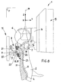
- Figure 1 an installation 1 for the cutting by carcass 2 of slaughter animals suspended by the rear legs from a conveyor 3 to continuous or discontinuous scrolling.
- the transporter 3 routes the carcasses 2 according to a longitudinal direction X, while the carcasses 2 suspended define a direction Z of elevation perpendicular to the longitudinal X direction.
- a transverse direction Y is perpendicular to the longitudinal directions X and Z elevation so that together these three directions X, Y, Z form a direct orthogonal coordinate system, by report in which this description is made.
- front are defined in relation to to the transverse Y direction, while the terms “On”, “under”, “above”, “below”, “top”, “Low” are defined with respect to the Z direction elevation.
- the conveyor 3 can be a conveyor of shape and suitable construction, allowing suspension of the carcass 2 via a hanger 5 such as a tinet with two branches at the ends of which the legs rear of the carcass 2 are hooked.
- a hanger 5 such as a tinet with two branches at the ends of which the legs rear of the carcass 2 are hooked.
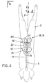
- the suspension of the carcass 2 is such that it has its ventral side and its internal dorsal side 8 to the body of section 6 and to the internal guide member 7, while it has its dorsal face 10 to the external member 9.
- the external guide member 9 comprises a movable arm 11 to a free end of which a device is pivotally mounted external guide 12, while the cutting member 6 and the internal guide member 7 are carried by the same so-called cutting set 13.
- the cutting assembly 13 comprises an extended beam 14 transversely and carrying the cutting member 6.
- the external guide member 9 is worn by a so-called external guide assembly 15 independent of the cutting assembly 13.
- the movable arm 11 is likely to be driven by a non-motor shown such as a hydraulic, pneumatic or analogous, of a displacement along arrow f1 such as illustrated in figure 1, so that the external guide 12 is pressed against the dorsal side external 10 of the carcass 2, or vice versa depending on the arrow f2 so that the external guide device 12 releases this external dorsal face 10.
- a non-motor shown such as a hydraulic, pneumatic or analogous, of a displacement along arrow f1 such as illustrated in figure 1, so that the external guide 12 is pressed against the dorsal side external 10 of the carcass 2, or vice versa depending on the arrow f2 so that the external guide device 12 releases this external dorsal face 10.
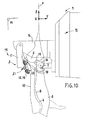
- the external guide member 9 is carried by the cutting assembly 13; for example the beam 14 bearing the cutting member 6 also carries the movable arm 11, pivotally mounted on the beam 14, in an elevation plane cross.
- the movable arm 11 can be animated by a rotation movement according to arrow f3 shown in figure 10.
- the cutting member 6 can be a circular saw, while that the internal guide member 7 may include a spreader 16 carrying two guide rollers 17, 18 cooperating with the internal dorsal face 8 of the carcass 2 when cutting it ( Figures 1, 8, 9 and 10).
- the internal 7 and external 9 guide members act, at the as they progress along the column vertebral 4 of the carcass 2, so as to make coincide the section plane P and the plane of symmetry of the column vertebral 4 to obtain a division of the carcass 2 into two substantially equal half-carcasses.
- the cutting taking place in an atmosphere loaded with water vapor and fat, the dorsal side carcass is slippery, which harms also to the positioning of the external guide member 9, and the maintenance of the carcass by the latter.
- the cutting process described above further provides for pinching the dorsal side external 10 of the carcass 2 to ensure a firm hold of the carcass during its cutting, applying against the external dorsal side 10 of the carcass 2 the device external guide 12 and by moving it according to the plane cutting P.
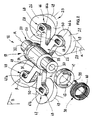
- This device 12 which is now described in detail in reference to Figures 2 to 7, is provided to ensure that pinching when moving along the cutting plane P.
- the guide device 12 is located under the shape of a lifting beam 19, pivotally mounted on a part free end 21 of the movable arm 11 forming a yoke, by means a hub 20.
- the chassis 22 has a symmetry with respect to a plane denoted S which, when the spreader 19 is applied against the outer dorsal face 10 of the carcass 2, is substantially coincident with the plane P cutting.
- the hub 20 is fixed to remains on the external face 24 of the chassis 22.
- the spreader 19 can pivot around an axis of rotation R longitudinal, coincident with the axis of the hub 20, and substantially perpendicular to the plane S of symmetry of the chassis 22.
- the hub 20 is presented, according to one embodiment illustrated in the figures, in the form of a drilled cylinder a bore 30 of axis R.
- the hub includes a middle portion 31 as well as two end portions 32, 33 whose diameter is less than that of the middle part 31, from which they are separated by two shoulders 34, 35.
- a shaft 36 is introduced into the bore 30 and associated with its two ends to a yoke 37 which is provided with free end portion 21 of the movable arm 11.
- This assembly allows the hub 20, and therefore the spreader, to pivot around its axis R relative to the movable arm 11.
- At least one elastic return member 38 such as a torsion spring, disposed between the lifter 19 and the movable arm 11.
- the external guide device 12 comprises two coil springs 38 each fitted on an end portion 32, 33 of the hub 20.
- Each spring 38 comprises for example two projections terminals 39, 40, one of which 39 is threaded in a oblong window 41 formed in a ring 42, 43 fitted on the extreme part 32, 33 of the hub 20, against the corresponding shoulder 34, 35.
- the ring 42, 43 is kept fixed in rotation for example via a key, a pin, or similar.
- the ring 42, 43 is kept fixed in rotation on the hub 20 by means of a grub screw 45 which crosses radially the ring 42, 43 and presses on the outer surface of the hub 20, which allows adjustment of the angular position of the spreader 19 relative to the movable arm 11.
- chassis is meant any type of support structure for the rollers 26, 27.
- the chassis 22 comprises by elsewhere a pair 46 of branches 46a, 46b extended on one side and on the other side of the plane S of symmetry.
- the chassis 22 is provided with two pairs of branches: an upper pair 46 of branches 46a, 46b, and a lower pair 47 of branches 47a, 47b, which form together a cross extending on either side of the hub 20 and on either side of the plane S of symmetry.
- pairs 46, 47 of branches 46a, 46b, 47a, 47b carry then each a pair 25 of rollers 26, 27 arranged substantially symmetrically with respect to the plane of symmetry S.
- Each branch 46a, 46b, 47a, 47b has a part extreme free 48 on which a roller 26, 27 is mounted, which can pivot relative to the branch about its axis of rotation 28, 29.
- the chassis 22 is in the form a ramp extended substantially along the cutting plane P.
- This ramp is for example provided with a plurality of pairs of branches each carrying a pebble.
- This ramp can be articulated to adapt to the contour of the spine 4 of the carcass 2.
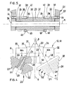
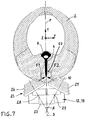
- each roller 26, 27 has a surface outer 49 intended to be supported on the dorsal side external 10 of the carcass 2 when the device 12 is applied against this dorsal face 10.
- This surface 49 has a symmetry of revolution around of the axis of rotation 28, 29 of the roller 26, 27.
- this surface 49 is frustoconical.
- the roller 26, 27 presents a base surface 50 and a vertex surface 51 circular, the diameter of the base surface 50 being greater than the diameter of the apex surface 51.
- the roller 26, 27 is fixed to the branch 46a, 46b, 47a, 47b so that its surface base 50 is turned towards the chassis 22, the surface of vertex 51 being located at a distance from the chassis 22.
- Each roller 26, 27 has a taper whose opening angular, denoted ⁇ , is chosen according to the conformation of the dorsal side 10 of the carcasses 2 to cut.
- the angular opening ⁇ is for example between 5 ° and 120 °. According to an embodiment illustrated on the Figures 4 and 7, this angular opening ⁇ is 70 ° about.
- guide device 12 conventional devices, including rollers, generally frustoconical to adapt to the curved shape of the external dorsal side of the carcass, rotate around axes perpendicular to the cutting plane.
- the combination of the support forces F1 and F2 causes, when the rollers 26, 27 roll on the dorsal face external 10 in a direction indicated by the arrows f4 shown in Figure 6, a pinch of the dorsal side external 10 which allows firm support of the carcass 2 and prevents it from pivoting around the spine 4 when of its cut.
- the technical effect would be at least partly due to the effects of varying rotational speeds on tapered pebbles.
- the angle, denoted ⁇ , formed by the axes of rotation 28, 29 of the rollers 26, 27 of the same pair 25 is for example included between 40 ° and 120 °.
- the angle ⁇ is substantially equal to 60 °.
- each roller 26, 27 can comprise at least one groove 52 formed in its outer surface 49.
- This groove 52 has for example a symmetry of revolution around the axis of rotation 28, 29 of the roller 26, 27.
- This groove can be rectangular, square, pseudo-rectangular, pseudo-square, or even semi-circular in a plane containing the axis 28, 29 of the roller 26, 27.
- each roller 26, 27 comprises a plurality of grooves 52 coaxial, such as the one just described, spaced from each other, arranged in the surface outside 50 of the roller 26, 27.
- These grooves 52 give the rollers 26, 27 properties non-slip to improve the maintenance of carcass 2 by the guide device 12.
- grooves 52 allow in particular the evacuation, during the rollers 26, 27 on the outer dorsal face 10 carcass 2, liquids present on it, at the way of the relief of a vehicle tire draining water present on the floor.
- the chassis 22 can be made at least partially of metal, by example in steel, while the rollers 26, 27 can be made of a synthetic polymer material such as polyamide fiber easy to mold and / or machine.
- the guide device 12 can also include means for adjusting the angle between the axes of rotation 28, 29 of the rollers 26, 27 of the same pair 25 to adapt to the conformation of the outer dorsal face 10 of the carcass 2.
- the lifter is effective even when a precut operation is performed on the dorsal side.
- the lifter allows a refocusing of the flesh and the processes which precedes cutting with the saw blade. It is so effective even if you removed before cutting the carcass in half carcasses an area 53 (figure 7), for the making, for example, Canadian bacon or lonzo Italian.
Landscapes
- Life Sciences & Earth Sciences (AREA)
- Engineering & Computer Science (AREA)
- Food Science & Technology (AREA)
- Processing Of Meat And Fish (AREA)
- Tires In General (AREA)
- Tyre Moulding (AREA)
- Treatment Of Fiber Materials (AREA)
- Nonmetal Cutting Devices (AREA)
- Knives (AREA)
Claims (13)
- Führungsvorrichtung, das gegen die äußere Rückseite (10) eines Tiergerippes (2) bei dessen Zerschneiden angelegt werden kann, wobei die besagte Vorrichtung (12) umfasst:wobei die besagte Vorrichtung (12) dadurch gekennzeichnet ist, dass sie in Form eines Steuerhebels (19) ausgebildet ist, mit einer an der Außenseite (24) des Gestells (22) befestigten Nabe (20), wobei das Gestell (22) mindestens ein Paar (46) Schenkel (46a, 46b) aufweist, auf denen jeweils eine Rolle (26, 27) drehbar montiert ist.ein Gestell (22), das eine Innenseite (2) umfasst, die zur äußeren Rückseite (10) des Gerippes (2) hin gerichtet werden soll, sowie eine Außenseite (24), die der besagten Innenseite (23) gegenüberliegt; undmindestens ein Paar (25) Schlepprollen (26, 27), die um Rotationsachsen (28, 29) herum auf das Gestell (22) montiert sind, wobei jede Rolle (26, 27) eine Außenfläche (49) aufweist, die gegen die äußere Rückseite (10) des Gerippes (2) angelegt werden kann, wobei die Rotationsachsen (28, 29) der Rollen (26, 27) eines gleichen Paares (25) gemeinsam ein "V" bilden, dessen Öffnung in die gleiche Richtung gerichtet ist wie die Innenseite (23) des Gestells (22),
- Führungsvorrichtung nach Anspruch 1, dadurch gekennzeichnet, dass jede Rolle (26, 27) die Form eines Rotationskegelstumpfes aufweist, dessen Achse etwa mit der Rotationsachse (28, 29) der Rolle (26, 27) übereinstimmt, und dessen Basis (50) zum Gestell (22) hin gerichtet ist.
- Führungsvorrichtung nach Anspruch 1 oder Anspruch 2, dadurch gekennzeichnet, dass jede Rolle (26, 27) mindestens einen in der Außenfläche (49) der Rolle (26, 27) vorgesehenen Hals (52) umfasst, wobei dieser Hals (52) eine Rotationssymmetrie um die Rotationsachse (28, 29) der Rolle (26, 27) herum aufweist.
- Führungsvorrichtung nach einem der Ansprüche 1 bis 3, dadurch gekennzeichnet, dass jede Rolle (26, 27) eine Mehrzahl von koaxialen, im Abstand zueinander angeordneten Hälsen (52) umfasst, die in der Außenfläche (49) der Rolle (26, 27) vorgesehen sind und jeweils eine Rotationssymmetrie um die Rotationsachse (28, 29) der Rolle (26, 27) herum aufweisen.
- Führungsvorrichtung nach einem der Ansprüche 1 bis 4, dadurch gekennzeichnet, dass der von den Rotationsachsen (28, 29) der Rollen (26, 27) eines gleichen Paares (25) gebildete Winkel (β) zwischen 60° und 140° beträgt.
- Führungsvorrichtung nach einem der Ansprüche 1 bis 5, dadurch gekennzeichnet, dass die besagten Rollen (26, 27) aus einem synthetischen Polymermaterial hergestellt sind.
- Vorrichtung nach einem der Ansprüche 1 bis 6, dadurch gekennzeichnet, dass das Gestell (22) zwei überkreuz angeordnete Paare (46, 47) Schenkel (46a, 46b; 47a, 47b) umfasst, wobei eine Rolle (26, 27) schwenkbar auf jedem Schenkel (46a, 46b; 47a, 47b) montiert ist.
- Zerschneidungsanlage von hängenden Gerippen (2) von Schlachttieren, mit:dadurch gekennzeichnet, dass des äußere Führungsorgan (9) eine Führungsvorrichtung (12) nach einem der Ansprüche 1 bis 7 umfasst.einem Schneidorgan (6), das sich nach einer so genannten Schneidebene (P) verschieben kann, um ein Gerippe (2) zumindest teilweise zu zerschneiden;einem unter dem Schneidorgan (6) angeordneten internen Führungsorgan (9), das gegen eine innere Rückseite (8) des Gerippes angelegt werden kann; undeinem externen Führungsorgan (9), das gegen das interne Führungsorgan (9) gegen eine äußere Rückseite (10) des Gerippes (2) angelegt werden kann,
- Anlage nach Anspruch 8, dadurch gekennzeichnet, dass die besagte äußere Führungsvorrichtung (12) drehbar an einem mobilen Arm (11) montiert ist, der von einem Balken (14) getragen wird, der ebenfalls das Schneidorgan (6) trägt.
- Anlage nach Anspruch 8, dadurch gekennzeichnet, dass die besagte äußere Führungsvorrichtung (12) drehbar an einem mobilen Arm (11) montiert ist, der unabhängig vom Schneidorgan (6) ist.
- Anlage nach Anspruch 9 oder Anspruch 10, dadurch gekennzeichnet, dass die besagte äußere Führungsvorrichtung (12) einen Steuerhebel (19) bildet, der schwenkbar über eine Nabe (20) am mobilen Arm (11) montiert ist, wobei die besagte Vorrichtung (12) in Bezug auf die Achse der Nabe (20) schwenkbar ist.
- Anlage nach einem der Ansprüche 8 bis 10, dadurch gekennzeichnet, dass die besagte äußere Führungsvorrichtung (12) ein federndes Rückstellorgan (38) umfasst, das die Winkelposition der äußeren Führungsvorrichtung (12) in Bezug auf den mobilen Arm (11) steuern kann.
- Zerschneidungsverfahren von Gerippen (2) von Schlachttieren, das die folgenden Etappen umfasst:wobei das besagte Verfahren dadurch gekennzeichnet ist, dass es ferner eine Etappe zum Einklemmen der äußeren Rückseite (10) des Gerippes (2) umfasst, um sein Festhalten bei seinem Zerschneiden zu gewährleisten, wobei gegen die äußere Rückseite (10) des Gerippes (2) eine Führungsvorrichtung (12) nach einem der Ansprüche 1 bis 7 angelegt und diese nach der besagten Schneidebene (P) versetzt wird.Einführen eines Schneidorgans (6) über die offene Bauchseite des Gerippes (2);Anlegen eines inneren Führungsorgans (9) gegen eine innere Rückseite (8) des Gerippes (2);Anlegen eines äußeren Führungsorgans (9) gegen eine äußere Rückseite (10) des Gerippes (2), gegen das innere Pührungsorgan (8) ;Einschalten des Schneidorgans (6) ;Versetzen der Baugruppe nach einer Schnittebene (P) ;
Applications Claiming Priority (2)
| Application Number | Priority Date | Filing Date | Title |
|---|---|---|---|
| FR0002045A FR2805129B1 (fr) | 2000-02-18 | 2000-02-18 | Dispositif de guidage pour la decoupe de carcasses d'animaux de boucheries, installation pour la decoupe de carcasses comprenant un tel dispositif, et procede de decoupe de carcasses |
| FR0002045 | 2000-02-18 |
Publications (3)
| Publication Number | Publication Date |
|---|---|
| EP1125501A2 EP1125501A2 (de) | 2001-08-22 |
| EP1125501A3 EP1125501A3 (de) | 2001-10-10 |
| EP1125501B1 true EP1125501B1 (de) | 2003-05-21 |
Family
ID=8847146
Family Applications (1)
| Application Number | Title | Priority Date | Filing Date |
|---|---|---|---|
| EP01400126A Expired - Lifetime EP1125501B1 (de) | 2000-02-18 | 2001-01-17 | Vorrichtung zum Spalten von Schlachttierkörpern, Anlage zum Spalten von Schlachttierkörpern mit solcher Vorrichtung und Verfahren zum Spalten von Schlachttierkörpern |
Country Status (5)
| Country | Link |
|---|---|
| EP (1) | EP1125501B1 (de) |
| AT (1) | ATE240652T1 (de) |
| DE (1) | DE60100277T2 (de) |
| DK (1) | DK1125501T3 (de) |
| FR (1) | FR2805129B1 (de) |
Families Citing this family (5)
| Publication number | Priority date | Publication date | Assignee | Title |
|---|---|---|---|---|
| FR2870090B1 (fr) * | 2004-05-17 | 2006-08-04 | Durand Internat Sa | Systeme de guidage externe d'une carcasse comprenant un dispositif de limitation angulaire |
| FR2874790B1 (fr) | 2004-09-07 | 2006-11-17 | Durand Internat Soc Par Action | Galets de guidage pour installation de fendage de carcasses d'animaux |
| DE202008008813U1 (de) | 2008-05-09 | 2008-10-16 | Banss Schlacht- und Fördertechnik GmbH | Anordnung zum Spalten eines Schlachttieres |
| ES2702423A1 (es) | 2017-08-31 | 2019-02-28 | Aira Robotics S L | Dispositivo de corte frontal y dorsal de una carcasa de cerdo |
| ES2926000A1 (es) * | 2021-04-09 | 2022-10-20 | Aira Robotics S L | Dispositivo de corte por la mitad de una carcasa de animal y robot que incorpora dicho dispositivo de corte |
Family Cites Families (4)
| Publication number | Priority date | Publication date | Assignee | Title |
|---|---|---|---|---|
| DE1189404B (de) * | 1960-02-19 | 1965-03-18 | Antonin Koettner | Vorrichtung zum Halbieren von geschlachtetem Grossvieh in haengender Lage |
| FR2535944A1 (fr) | 1982-11-15 | 1984-05-18 | Schlumberger Cie N | Machine automatique a fendre les animaux de boucherie, notamment les porcs |
| DE3247588C2 (de) * | 1982-12-22 | 1986-11-06 | Banss Kg Maschinenfabrik, 3560 Biedenkopf | Vorrichtung zum Halbieren von Schlachttierkörpern durch Sägen |
| FR2747538B1 (fr) | 1996-04-18 | 1998-06-05 | Durand International | Procede et dispositif de guidage dorsal pour la fente d'une carcasse d'animal de boucherie |
-
2000
- 2000-02-18 FR FR0002045A patent/FR2805129B1/fr not_active Expired - Fee Related
-
2001
- 2001-01-17 EP EP01400126A patent/EP1125501B1/de not_active Expired - Lifetime
- 2001-01-17 DK DK01400126T patent/DK1125501T3/da active
- 2001-01-17 DE DE60100277T patent/DE60100277T2/de not_active Expired - Fee Related
- 2001-01-17 AT AT01400126T patent/ATE240652T1/de not_active IP Right Cessation
Also Published As
| Publication number | Publication date |
|---|---|
| FR2805129A1 (fr) | 2001-08-24 |
| ATE240652T1 (de) | 2003-06-15 |
| DE60100277D1 (de) | 2003-06-26 |
| DE60100277T2 (de) | 2004-04-01 |
| FR2805129B1 (fr) | 2005-02-18 |
| EP1125501A3 (de) | 2001-10-10 |
| DK1125501T3 (da) | 2003-09-22 |
| EP1125501A2 (de) | 2001-08-22 |
Similar Documents
| Publication | Publication Date | Title |
|---|---|---|
| CA2185820C (fr) | Procede et dispositif pour la fente d'une carcasse d'animal de boucherie | |
| FR2596948A1 (fr) | Appareil a ebrancher les troncs d'arbres | |
| FR2496539A1 (fr) | Porte-couteau a commande hydraulique | |
| EP1125501B1 (de) | Vorrichtung zum Spalten von Schlachttierkörpern, Anlage zum Spalten von Schlachttierkörpern mit solcher Vorrichtung und Verfahren zum Spalten von Schlachttierkörpern | |
| EP0377542B1 (de) | Einstellbare innere Führungseinrichtung für eine Vorrichtung zum Zerschneiden des Gerippes von Schlachttieren und Verfahren für dieses Zerschneiden | |
| FR2719516A1 (fr) | Outillage pour le toilage de portées cylindriques avec contrôle de diamètre des portées. | |
| EP0801900B1 (de) | Verfahren und Vorrichtung zur dorsalen Führung beim Spalten von Schlachttierkörpern | |
| EP0300940B1 (de) | Verfahren und Vorrichtung zum Ausbeinen von einem Schlacht-Hinterteil | |
| EP0624431A1 (de) | Bandschleifmaschine für zylindrische Werkstücke | |
| LU82350A1 (fr) | Machine pour le refendage de brames par oxycoupage | |
| FR2794612A1 (fr) | Tete d'ebranchage et de coupe d'une machine de ramassage | |
| CA2639355A1 (fr) | Entrainement d'un chariot porte outil de fente d'une machine a fendre les carcasses d'animaux | |
| FR2891987A1 (fr) | Dispositif pour realiser une taille cylindrique de la base du tronc d'arbres sur pied. | |
| CA2192227A1 (fr) | Dispositif automatique pour couper les pattes de carcasses de porc | |
| FR2655285A1 (fr) | Machine a affuter les couteaux. | |
| FR2870090A1 (fr) | Systeme de guidage externe d'une carcasse comprenant un dispositif de limitation angulaire | |
| FR3031688A1 (fr) | Machine a couper ou trancher multi-couteaux | |
| CA2890464A1 (fr) | Machine et procede pour le fractionnement en morceaux de parties de pneumatiques en fin de vie | |
| EP3047722B1 (de) | Verbessertes schneidewerkzeug mit amboss | |
| FR2919473A1 (fr) | Sciage de carcasses de porc ou analogue | |
| FR2884746A1 (fr) | Dispositif pour affiler un tranchant de lame | |
| FR2506271A1 (fr) | Dispositif transporteur pour faire avancer les betes de boucherie | |
| FR2660837A2 (fr) | Procede pour depouiller la tete et les membres d'animaux d'abattoirs et dispositif pour sa mise en óoeuvre. | |
| EP0722849B1 (de) | Lenkrolle mit einstellbarer Richtungsverriegelung | |
| FR2486435A1 (fr) | Dispositif destine a la presentation de toutes pieces de coutellerie pourvues d'une soie a un dispositif de polissage |
Legal Events
| Date | Code | Title | Description |
|---|---|---|---|
| PUAI | Public reference made under article 153(3) epc to a published international application that has entered the european phase |
Free format text: ORIGINAL CODE: 0009012 |
|
| AK | Designated contracting states |
Kind code of ref document: A2 Designated state(s): AT BE CH CY DE DK ES FI FR GB GR IE IT LI LU MC NL PT SE TR |
|
| AX | Request for extension of the european patent |
Free format text: AL;LT;LV;MK;RO;SI |
|
| PUAL | Search report despatched |
Free format text: ORIGINAL CODE: 0009013 |
|
| AK | Designated contracting states |
Kind code of ref document: A3 Designated state(s): AT BE CH CY DE DK ES FI FR GB GR IE IT LI LU MC NL PT SE TR |
|
| AX | Request for extension of the european patent |
Free format text: AL;LT;LV;MK;RO;SI |
|
| 17P | Request for examination filed |
Effective date: 20011127 |
|
| 17Q | First examination report despatched |
Effective date: 20020225 |
|
| AKX | Designation fees paid |
Free format text: AT BE CH CY DE DK ES FI FR GB GR IE IT LI LU MC NL PT SE TR |
|
| GRAH | Despatch of communication of intention to grant a patent |
Free format text: ORIGINAL CODE: EPIDOS IGRA |
|
| GRAH | Despatch of communication of intention to grant a patent |
Free format text: ORIGINAL CODE: EPIDOS IGRA |
|
| GRAA | (expected) grant |
Free format text: ORIGINAL CODE: 0009210 |
|
| AK | Designated contracting states |
Designated state(s): AT BE CH CY DE DK ES FI FR GB GR IE IT LI LU MC NL PT SE TR |
|
| PG25 | Lapsed in a contracting state [announced via postgrant information from national office to epo] |
Ref country code: IE Free format text: LAPSE BECAUSE OF NON-PAYMENT OF DUE FEES Effective date: 20030521 Ref country code: IT Free format text: LAPSE BECAUSE OF FAILURE TO SUBMIT A TRANSLATION OF THE DESCRIPTION OR TO PAY THE FEE WITHIN THE PRESCRIBED TIME-LIMIT;WARNING: LAPSES OF ITALIAN PATENTS WITH EFFECTIVE DATE BEFORE 2007 MAY HAVE OCCURRED AT ANY TIME BEFORE 2007. THE CORRECT EFFECTIVE DATE MAY BE DIFFERENT FROM THE ONE RECORDED. Effective date: 20030521 Ref country code: TR Free format text: LAPSE BECAUSE OF FAILURE TO SUBMIT A TRANSLATION OF THE DESCRIPTION OR TO PAY THE FEE WITHIN THE PRESCRIBED TIME-LIMIT Effective date: 20030521 Ref country code: GB Free format text: LAPSE BECAUSE OF FAILURE TO SUBMIT A TRANSLATION OF THE DESCRIPTION OR TO PAY THE FEE WITHIN THE PRESCRIBED TIME-LIMIT Effective date: 20030521 Ref country code: AT Free format text: LAPSE BECAUSE OF FAILURE TO SUBMIT A TRANSLATION OF THE DESCRIPTION OR TO PAY THE FEE WITHIN THE PRESCRIBED TIME-LIMIT Effective date: 20030521 Ref country code: CY Free format text: LAPSE BECAUSE OF FAILURE TO SUBMIT A TRANSLATION OF THE DESCRIPTION OR TO PAY THE FEE WITHIN THE PRESCRIBED TIME-LIMIT Effective date: 20030521 Ref country code: FI Free format text: LAPSE BECAUSE OF FAILURE TO SUBMIT A TRANSLATION OF THE DESCRIPTION OR TO PAY THE FEE WITHIN THE PRESCRIBED TIME-LIMIT Effective date: 20030521 |
|
| REG | Reference to a national code |
Ref country code: GB Ref legal event code: FG4D Free format text: NOT ENGLISH |
|
| REG | Reference to a national code |
Ref country code: CH Ref legal event code: EP |
|
| REG | Reference to a national code |
Ref country code: IE Ref legal event code: FG4D Free format text: FRENCH |
|
| REF | Corresponds to: |
Ref document number: 60100277 Country of ref document: DE Date of ref document: 20030626 Kind code of ref document: P |
|
| PG25 | Lapsed in a contracting state [announced via postgrant information from national office to epo] |
Ref country code: GR Free format text: LAPSE BECAUSE OF FAILURE TO SUBMIT A TRANSLATION OF THE DESCRIPTION OR TO PAY THE FEE WITHIN THE PRESCRIBED TIME-LIMIT Effective date: 20030821 Ref country code: PT Free format text: LAPSE BECAUSE OF FAILURE TO SUBMIT A TRANSLATION OF THE DESCRIPTION OR TO PAY THE FEE WITHIN THE PRESCRIBED TIME-LIMIT Effective date: 20030821 Ref country code: SE Free format text: LAPSE BECAUSE OF FAILURE TO SUBMIT A TRANSLATION OF THE DESCRIPTION OR TO PAY THE FEE WITHIN THE PRESCRIBED TIME-LIMIT Effective date: 20030821 |
|
| PG25 | Lapsed in a contracting state [announced via postgrant information from national office to epo] |
Ref country code: ES Free format text: LAPSE BECAUSE OF FAILURE TO SUBMIT A TRANSLATION OF THE DESCRIPTION OR TO PAY THE FEE WITHIN THE PRESCRIBED TIME-LIMIT Effective date: 20030901 |
|
| REG | Reference to a national code |
Ref country code: DK Ref legal event code: T3 |
|
| GBV | Gb: ep patent (uk) treated as always having been void in accordance with gb section 77(7)/1977 [no translation filed] |
Effective date: 20030521 |
|
| REG | Reference to a national code |
Ref country code: IE Ref legal event code: FD4D Ref document number: 1125501E Country of ref document: IE |
|
| PG25 | Lapsed in a contracting state [announced via postgrant information from national office to epo] |
Ref country code: LU Free format text: LAPSE BECAUSE OF NON-PAYMENT OF DUE FEES Effective date: 20040117 |
|
| PG25 | Lapsed in a contracting state [announced via postgrant information from national office to epo] |
Ref country code: BE Free format text: LAPSE BECAUSE OF NON-PAYMENT OF DUE FEES Effective date: 20040131 Ref country code: MC Free format text: LAPSE BECAUSE OF NON-PAYMENT OF DUE FEES Effective date: 20040131 |
|
| PLBE | No opposition filed within time limit |
Free format text: ORIGINAL CODE: 0009261 |
|
| STAA | Information on the status of an ep patent application or granted ep patent |
Free format text: STATUS: NO OPPOSITION FILED WITHIN TIME LIMIT |
|
| 26N | No opposition filed |
Effective date: 20040224 |
|
| BERE | Be: lapsed |
Owner name: *DURAND INTERNATIONAL Effective date: 20040131 |
|
| PG25 | Lapsed in a contracting state [announced via postgrant information from national office to epo] |
Ref country code: CH Free format text: LAPSE BECAUSE OF NON-PAYMENT OF DUE FEES Effective date: 20050131 Ref country code: LI Free format text: LAPSE BECAUSE OF NON-PAYMENT OF DUE FEES Effective date: 20050131 |
|
| REG | Reference to a national code |
Ref country code: CH Ref legal event code: PL |
|
| PGFP | Annual fee paid to national office [announced via postgrant information from national office to epo] |
Ref country code: DK Payment date: 20080215 Year of fee payment: 8 |
|
| PGFP | Annual fee paid to national office [announced via postgrant information from national office to epo] |
Ref country code: DE Payment date: 20080207 Year of fee payment: 8 Ref country code: NL Payment date: 20080203 Year of fee payment: 8 |
|
| PGFP | Annual fee paid to national office [announced via postgrant information from national office to epo] |
Ref country code: FR Payment date: 20080131 Year of fee payment: 8 |
|
| NLV4 | Nl: lapsed or anulled due to non-payment of the annual fee |
Effective date: 20090801 |
|
| REG | Reference to a national code |
Ref country code: DK Ref legal event code: EBP |
|
| PG25 | Lapsed in a contracting state [announced via postgrant information from national office to epo] |
Ref country code: DE Free format text: LAPSE BECAUSE OF NON-PAYMENT OF DUE FEES Effective date: 20090801 |
|
| REG | Reference to a national code |
Ref country code: FR Ref legal event code: ST Effective date: 20091030 |
|
| PG25 | Lapsed in a contracting state [announced via postgrant information from national office to epo] |
Ref country code: NL Free format text: LAPSE BECAUSE OF NON-PAYMENT OF DUE FEES Effective date: 20090801 |
|
| PG25 | Lapsed in a contracting state [announced via postgrant information from national office to epo] |
Ref country code: FR Free format text: LAPSE BECAUSE OF NON-PAYMENT OF DUE FEES Effective date: 20090202 |
|
| PG25 | Lapsed in a contracting state [announced via postgrant information from national office to epo] |
Ref country code: DK Free format text: LAPSE BECAUSE OF NON-PAYMENT OF DUE FEES Effective date: 20090731 |