EP1125501B1 - Guiding device for splitting carcasses, apparatus for splitting carcasses comprising such device and method for splitting carcasses - Google Patents
Guiding device for splitting carcasses, apparatus for splitting carcasses comprising such device and method for splitting carcasses Download PDFInfo
- Publication number
- EP1125501B1 EP1125501B1 EP01400126A EP01400126A EP1125501B1 EP 1125501 B1 EP1125501 B1 EP 1125501B1 EP 01400126 A EP01400126 A EP 01400126A EP 01400126 A EP01400126 A EP 01400126A EP 1125501 B1 EP1125501 B1 EP 1125501B1
- Authority
- EP
- European Patent Office
- Prior art keywords
- carcass
- external
- roller
- cutting
- face
- Prior art date
- Legal status (The legal status is an assumption and is not a legal conclusion. Google has not performed a legal analysis and makes no representation as to the accuracy of the status listed.)
- Expired - Lifetime
Links
Images


Classifications
-
- A—HUMAN NECESSITIES
- A22—BUTCHERING; MEAT TREATMENT; PROCESSING POULTRY OR FISH
- A22B—SLAUGHTERING
- A22B5/00—Accessories for use during or after slaughtering
- A22B5/20—Splitting instruments
- A22B5/202—Guides or devices for holding the carcass during the splitting operation
-
- A—HUMAN NECESSITIES
- A22—BUTCHERING; MEAT TREATMENT; PROCESSING POULTRY OR FISH
- A22B—SLAUGHTERING
- A22B5/00—Accessories for use during or after slaughtering
- A22B5/20—Splitting instruments
- A22B5/203—Meat or bone saws for splitting carcasses
- A22B5/206—Disc or circular saws
Definitions
- the invention relates to the field of animal slaughter butcheries, and applies to the cutting of carcasses of animals, which can be pigs, sheep or cattle.
- the invention relates to a guide device capable of press on the outer dorsal side of a carcass of a animal, when cutting it.
- It also relates to an installation for cutting hanging carcasses of meat animals including a such a device, as well as a process for cutting carcasses slaughter animals at least one of which is implementation by this device.
- the guide members aim precisely to immobilize the carcass for holding the cutting member in a position central along the spine.
- the document EP-801 900 describes a device for guide with idler rollers on the head frame cutting.
- the document FR 2 535 944 describes a device for guide with movable idle rollers along a column of external guidance opposite the cutting column.
- Other systems use rollers mounted on a point fixed.
- the axes of rotation of the rollers are not perpendicular to the cutting plane.
- the Applicant has found that the rocking of the carcass is limited by the combination of the application of the internal guide member against the internal dorsal face of the carcass, and of the application of the guide member external against the external dorsal side of the carcass to against the internal guide member.
- these devices do not always allow when a saw blade, guarantee optimal cutting of all processes, especially when the carcasses have defects in symmetry, a quality criterion required in certain slaughterhouses.
- the invention aims to overcome in particular the drawbacks above of the prior art, by proposing a device for carcass guiding to ensure support closes the carcass without slipping or sliding on it.
- the invention also aims to refocus and maintain the meats and the processes before the passage of the blade saw to allow excellent cutting.
- a first object of the invention is a guide device capable of pressing on the dorsal side external of an animal carcass, when cutting this, as described in claim 1.
- the guide device exerts on the face external dorsal of the carcass a pinch force which ensures firm support of the carcass during its cutting, and thus improves the quality of the cutting as well as its yield.
- each roller has the shape of a truncated cone of revolution whose axis is substantially coincides with the axis of rotation of the roller, and whose base is facing the chassis.
- each roller can include at least one groove formed in the outer surface of the roller, this groove having a symmetry of revolution around the axis of rotation of the roller.
- each roller comprises a plurality of grooves spaced apart from each other, arranged in the outer surface of the roller, each having a symmetry of revolution around the axis of rotation of the roller.
- the angle formed by the axes of rotation of the rollers of the same pair is between 60 ° and 140 °.
- the rollers can be made of a polymer material synthetic.
- the guide device is present in the form of a spreader spreader according to a so-called main steering, and includes a hub fixed to remains on the external face of the chassis, and whose axis is substantially perpendicular to said direction main.
- the chassis includes for example a pair of branches extended according to said main direction, on each which is pivotally mounted a roller.
- the chassis comprises two pairs of branches arranged in a cross, extended substantially in said main direction, a roller being pivotally mounted on each branch.
- the guide device is pivotally mounted on a movable arm carried by a beam which also carries the cutting member, or on a movable arm independent of the cutting member.
- the guiding device forms a lifting beam pivotally mounted on the movable arm at by means of a hub, the said device being able to pivot relative to the axis of the hub.
- the guide device may include a elastic return member capable of controlling the position angle of the guiding device with respect to the arm mobile.
- Figure 1 an installation 1 for the cutting by carcass 2 of slaughter animals suspended by the rear legs from a conveyor 3 to continuous or discontinuous scrolling.
- the transporter 3 routes the carcasses 2 according to a longitudinal direction X, while the carcasses 2 suspended define a direction Z of elevation perpendicular to the longitudinal X direction.
- a transverse direction Y is perpendicular to the longitudinal directions X and Z elevation so that together these three directions X, Y, Z form a direct orthogonal coordinate system, by report in which this description is made.
- front are defined in relation to to the transverse Y direction, while the terms “On”, “under”, “above”, “below”, “top”, “Low” are defined with respect to the Z direction elevation.
- the conveyor 3 can be a conveyor of shape and suitable construction, allowing suspension of the carcass 2 via a hanger 5 such as a tinet with two branches at the ends of which the legs rear of the carcass 2 are hooked.
- a hanger 5 such as a tinet with two branches at the ends of which the legs rear of the carcass 2 are hooked.
- the suspension of the carcass 2 is such that it has its ventral side and its internal dorsal side 8 to the body of section 6 and to the internal guide member 7, while it has its dorsal face 10 to the external member 9.
- the external guide member 9 comprises a movable arm 11 to a free end of which a device is pivotally mounted external guide 12, while the cutting member 6 and the internal guide member 7 are carried by the same so-called cutting set 13.
- the cutting assembly 13 comprises an extended beam 14 transversely and carrying the cutting member 6.
- the external guide member 9 is worn by a so-called external guide assembly 15 independent of the cutting assembly 13.
- the movable arm 11 is likely to be driven by a non-motor shown such as a hydraulic, pneumatic or analogous, of a displacement along arrow f1 such as illustrated in figure 1, so that the external guide 12 is pressed against the dorsal side external 10 of the carcass 2, or vice versa depending on the arrow f2 so that the external guide device 12 releases this external dorsal face 10.
- a non-motor shown such as a hydraulic, pneumatic or analogous, of a displacement along arrow f1 such as illustrated in figure 1, so that the external guide 12 is pressed against the dorsal side external 10 of the carcass 2, or vice versa depending on the arrow f2 so that the external guide device 12 releases this external dorsal face 10.
- the external guide member 9 is carried by the cutting assembly 13; for example the beam 14 bearing the cutting member 6 also carries the movable arm 11, pivotally mounted on the beam 14, in an elevation plane cross.
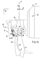
- the movable arm 11 can be animated by a rotation movement according to arrow f3 shown in figure 10.
- the cutting member 6 can be a circular saw, while that the internal guide member 7 may include a spreader 16 carrying two guide rollers 17, 18 cooperating with the internal dorsal face 8 of the carcass 2 when cutting it ( Figures 1, 8, 9 and 10).
- the internal 7 and external 9 guide members act, at the as they progress along the column vertebral 4 of the carcass 2, so as to make coincide the section plane P and the plane of symmetry of the column vertebral 4 to obtain a division of the carcass 2 into two substantially equal half-carcasses.
- the cutting taking place in an atmosphere loaded with water vapor and fat, the dorsal side carcass is slippery, which harms also to the positioning of the external guide member 9, and the maintenance of the carcass by the latter.
- the cutting process described above further provides for pinching the dorsal side external 10 of the carcass 2 to ensure a firm hold of the carcass during its cutting, applying against the external dorsal side 10 of the carcass 2 the device external guide 12 and by moving it according to the plane cutting P.
- This device 12 which is now described in detail in reference to Figures 2 to 7, is provided to ensure that pinching when moving along the cutting plane P.
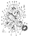
- the guide device 12 is located under the shape of a lifting beam 19, pivotally mounted on a part free end 21 of the movable arm 11 forming a yoke, by means a hub 20.
- the chassis 22 has a symmetry with respect to a plane denoted S which, when the spreader 19 is applied against the outer dorsal face 10 of the carcass 2, is substantially coincident with the plane P cutting.
- the hub 20 is fixed to remains on the external face 24 of the chassis 22.
- the spreader 19 can pivot around an axis of rotation R longitudinal, coincident with the axis of the hub 20, and substantially perpendicular to the plane S of symmetry of the chassis 22.
- the hub 20 is presented, according to one embodiment illustrated in the figures, in the form of a drilled cylinder a bore 30 of axis R.
- the hub includes a middle portion 31 as well as two end portions 32, 33 whose diameter is less than that of the middle part 31, from which they are separated by two shoulders 34, 35.
- a shaft 36 is introduced into the bore 30 and associated with its two ends to a yoke 37 which is provided with free end portion 21 of the movable arm 11.
- This assembly allows the hub 20, and therefore the spreader, to pivot around its axis R relative to the movable arm 11.
- At least one elastic return member 38 such as a torsion spring, disposed between the lifter 19 and the movable arm 11.
- the external guide device 12 comprises two coil springs 38 each fitted on an end portion 32, 33 of the hub 20.
- Each spring 38 comprises for example two projections terminals 39, 40, one of which 39 is threaded in a oblong window 41 formed in a ring 42, 43 fitted on the extreme part 32, 33 of the hub 20, against the corresponding shoulder 34, 35.
- the ring 42, 43 is kept fixed in rotation for example via a key, a pin, or similar.
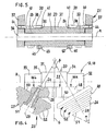
- the ring 42, 43 is kept fixed in rotation on the hub 20 by means of a grub screw 45 which crosses radially the ring 42, 43 and presses on the outer surface of the hub 20, which allows adjustment of the angular position of the spreader 19 relative to the movable arm 11.
- chassis is meant any type of support structure for the rollers 26, 27.
- the chassis 22 comprises by elsewhere a pair 46 of branches 46a, 46b extended on one side and on the other side of the plane S of symmetry.
- the chassis 22 is provided with two pairs of branches: an upper pair 46 of branches 46a, 46b, and a lower pair 47 of branches 47a, 47b, which form together a cross extending on either side of the hub 20 and on either side of the plane S of symmetry.
- pairs 46, 47 of branches 46a, 46b, 47a, 47b carry then each a pair 25 of rollers 26, 27 arranged substantially symmetrically with respect to the plane of symmetry S.
- Each branch 46a, 46b, 47a, 47b has a part extreme free 48 on which a roller 26, 27 is mounted, which can pivot relative to the branch about its axis of rotation 28, 29.
- the chassis 22 is in the form a ramp extended substantially along the cutting plane P.
- This ramp is for example provided with a plurality of pairs of branches each carrying a pebble.
- This ramp can be articulated to adapt to the contour of the spine 4 of the carcass 2.
- each roller 26, 27 has a surface outer 49 intended to be supported on the dorsal side external 10 of the carcass 2 when the device 12 is applied against this dorsal face 10.
- This surface 49 has a symmetry of revolution around of the axis of rotation 28, 29 of the roller 26, 27.
- this surface 49 is frustoconical.
- the roller 26, 27 presents a base surface 50 and a vertex surface 51 circular, the diameter of the base surface 50 being greater than the diameter of the apex surface 51.
- the roller 26, 27 is fixed to the branch 46a, 46b, 47a, 47b so that its surface base 50 is turned towards the chassis 22, the surface of vertex 51 being located at a distance from the chassis 22.
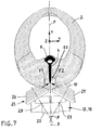
- Each roller 26, 27 has a taper whose opening angular, denoted ⁇ , is chosen according to the conformation of the dorsal side 10 of the carcasses 2 to cut.
- the angular opening ⁇ is for example between 5 ° and 120 °. According to an embodiment illustrated on the Figures 4 and 7, this angular opening ⁇ is 70 ° about.
- guide device 12 conventional devices, including rollers, generally frustoconical to adapt to the curved shape of the external dorsal side of the carcass, rotate around axes perpendicular to the cutting plane.
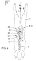
- the combination of the support forces F1 and F2 causes, when the rollers 26, 27 roll on the dorsal face external 10 in a direction indicated by the arrows f4 shown in Figure 6, a pinch of the dorsal side external 10 which allows firm support of the carcass 2 and prevents it from pivoting around the spine 4 when of its cut.
- the technical effect would be at least partly due to the effects of varying rotational speeds on tapered pebbles.
- the angle, denoted ⁇ , formed by the axes of rotation 28, 29 of the rollers 26, 27 of the same pair 25 is for example included between 40 ° and 120 °.
- the angle ⁇ is substantially equal to 60 °.
- each roller 26, 27 can comprise at least one groove 52 formed in its outer surface 49.
- This groove 52 has for example a symmetry of revolution around the axis of rotation 28, 29 of the roller 26, 27.
- This groove can be rectangular, square, pseudo-rectangular, pseudo-square, or even semi-circular in a plane containing the axis 28, 29 of the roller 26, 27.
- each roller 26, 27 comprises a plurality of grooves 52 coaxial, such as the one just described, spaced from each other, arranged in the surface outside 50 of the roller 26, 27.
- These grooves 52 give the rollers 26, 27 properties non-slip to improve the maintenance of carcass 2 by the guide device 12.
- grooves 52 allow in particular the evacuation, during the rollers 26, 27 on the outer dorsal face 10 carcass 2, liquids present on it, at the way of the relief of a vehicle tire draining water present on the floor.
- the chassis 22 can be made at least partially of metal, by example in steel, while the rollers 26, 27 can be made of a synthetic polymer material such as polyamide fiber easy to mold and / or machine.
- the guide device 12 can also include means for adjusting the angle between the axes of rotation 28, 29 of the rollers 26, 27 of the same pair 25 to adapt to the conformation of the outer dorsal face 10 of the carcass 2.
- the lifter is effective even when a precut operation is performed on the dorsal side.
- the lifter allows a refocusing of the flesh and the processes which precedes cutting with the saw blade. It is so effective even if you removed before cutting the carcass in half carcasses an area 53 (figure 7), for the making, for example, Canadian bacon or lonzo Italian.
Abstract
Description
L'invention est relative au domaine de l'abattage d'animaux de boucheries, et s'applique à la découpe des carcasses des animaux, qui peuvent être des porcins, des ovins ou des bovins.The invention relates to the field of animal slaughter butcheries, and applies to the cutting of carcasses of animals, which can be pigs, sheep or cattle.
L'invention concerne un dispositif de guidage apte à appuyer sur la face dorsale externe d'une carcasse d'un animal, lors de la découpe de celle-ci.The invention relates to a guide device capable of press on the outer dorsal side of a carcass of a animal, when cutting it.
Elle concerne également une installation pour la découpe de carcasses suspendues d'animaux de boucherie comprenant un tel dispositif, ainsi qu'un procédé de découpe de carcasses d'animaux de boucherie dont l'une des étapes au moins est mise en oeuvre par ce dispositif.It also relates to an installation for cutting hanging carcasses of meat animals including a such a device, as well as a process for cutting carcasses slaughter animals at least one of which is implementation by this device.
La découpe des carcasses, généralement suspendues par les pattes arrière, est pratiquée le plus souvent de la manière suivante, bien connue :
- on introduit un organe de coupe par la face ventrale ouverte de la carcasse ;
- on applique contre une face dorsale interne de la carcasse un organe de guidage interne ;
- on applique contre une face dorsale externe de la carcasse un organe de guidage externe à l'encontre de l'organe de guidage interne ;
- on met en fonction l'organe de coupe ;
- puis on déplace l'ensemble selon un plan de coupe.
- a cutting member is introduced through the open ventral face of the carcass;
- an internal guide member is applied against an internal dorsal face of the carcass;
- an external guide member is applied against an external dorsal face of the carcass against the internal guide member;
- the cutting member is put into operation;
- then the assembly is moved along a cutting plane.
Pour découper la carcasse d'une manière propre et nette, tout en garantissant une cadence de découpe répondant aux exigences des distributeurs, il est nécessaire d'immobiliser la carcasse pendant toute la durée de la découpe, d'une part en l'empêchant de se balancer, et d'autre part en l'empêchant de pivoter autour de l'axe formé par sa colonne vertébrale.To cut the carcass in a clean and neat way, while ensuring a cutting rate that meets the requirements of distributors, it is necessary immobilize the carcass for the duration of the cutting, on the one hand preventing it from swinging, and on the other hand by preventing it from pivoting around the axis formed by its spine.
Les organes de guidage visent précisément à immobiliser la carcasse pour maintenir l'organe de coupe dans une position centrale le long de la colonne vertébrale.The guide members aim precisely to immobilize the carcass for holding the cutting member in a position central along the spine.
On connaít plusieurs types de dispositifs de guidage
externe. Le document EP-801 900 décrit un dispositif de
guidage avec galets fous embarqué sur le chassis de la tête
de coupe. Le document FR 2 535 944 décrit un dispositif de
guidage avec galets fous mobiles le long d'une colonne de
guidage externe en vis-à-vis de la colonne de découpe.
D'autres systèmes utilisent des galets montés sur un point
fixe.We know several types of guide devices
external. The document EP-801 900 describes a device for
guide with idler rollers on the head frame
cutting. The
Tous ces dispositifs de l'art antérieur utilisent des moyens de guidage externe présentant des surfaces d'appui à symétrie de révolution d'axes perpendiculaires au plan de coupe. Typiquement dans le cas de galets, les axes de rotation d'une même paire de galets sont confondus et perpendiculaires au plan de coupe.All of these prior art devices use external guide means having bearing surfaces to symmetry of revolution of axes perpendicular to the plane of chopped off. Typically in the case of rollers, the axes of rotation of the same pair of rollers are confused and perpendicular to the cutting plane.
Dans d'autres documents, les axes de rotation des galets ne sont pas perpendiculaires au plan de coupe.In other documents, the axes of rotation of the rollers are not perpendicular to the cutting plane.
Dans le document DE 3 247 588, l'axe des galets est parallèle au plan de coupe, les galets de forme tronconique prenant appui sur les côtés de la carcasse.In document DE 3 247 588, the axis of the rollers is parallel to the cutting plane, the tapered rollers bearing on the sides of the carcass.
Dans le document DE 1189 404, les axes de rotation des galets forment un ensemble en V et sont inclinés par rapport au plan de coupe.In document DE 1189 404, the axes of rotation of the rollers form an assembly in V and are inclined relative to the cutting plane.
La demanderesse a constaté que le balancement de la carcasse est limité par la combinaison de l'application de l'organe de guidage interne contre la face dorsale interne de la carcasse, et de l'application de l'organe de guidage externe contre la face dorsale externe de la carcasse à l'encontre de l'organe de guidage interne.The Applicant has found that the rocking of the carcass is limited by the combination of the application of the internal guide member against the internal dorsal face of the carcass, and of the application of the guide member external against the external dorsal side of the carcass to against the internal guide member.
Cependant, la demanderesse a également constaté que les organes de guidage externe connus ne parviennent pas à enrayer le pivotement de la carcasse autour de sa colonne vertébrale.However, the Applicant has also found that the known external guide members fail to stop the pivoting of the carcass around its column spinal.
En effet, on constate un glissement ou un dérapage non souhaité des galets sur la face dorsale de la carcasse, dû à la combinaison de facteurs tels que :
- les vibrations dues à l'effort de coupe ;
- la présence d'un liquide plus ou moins visqueux (généralement un mélange d'eau et de graisse) sur la face dorsale de la carcasse ;
- l'écartement des deux demi-carcasses en formation provoqué par le passage de l'organe de coupe.
- vibrations due to the cutting force;
- the presence of a more or less viscous liquid (generally a mixture of water and fat) on the dorsal side of the carcass;
- the spacing of the two half-carcasses in formation caused by the passage of the cutting member.
De ce fait, les dispositifs de guidage connus ne permettent pas d'assurer un maintien optimal de la carcasse lors de sa découpe.Therefore, known guide devices do not allow not to ensure optimal maintenance of the carcass during its cutting.
De plus ces dispositifs ne permettent pas toujours lorsque l'on utilise comme organe de coupe une lame de scie, de garantir une découpe optimale de toutes les apophyses, notamment lorsque les carcasses présentent des défauts de symétrie, critère de qualité exigé dans certains abattoirs.In addition, these devices do not always allow when a saw blade, guarantee optimal cutting of all processes, especially when the carcasses have defects in symmetry, a quality criterion required in certain slaughterhouses.
L'invention vise à pallier notamment les inconvénients précité de l'art antérieur, en proposant un dispositif de guidage de la carcasse permettant d'assurer un maintien ferme de la carcasse sans glisser ni déraper sur celle-ci.The invention aims to overcome in particular the drawbacks above of the prior art, by proposing a device for carcass guiding to ensure support closes the carcass without slipping or sliding on it.
L'invention vise également à recentrer et maintenir les viandes et les apophyses avant le passage de la lame de scie pour permettre une excellente découpe.The invention also aims to refocus and maintain the meats and the processes before the passage of the blade saw to allow excellent cutting.
A cet effet, un premier objet de l'invention est un
dispositif de guidage apte à appuyer sur la face dorsale
externe d'une carcasse d'un animal, lors de la découpe de
celle-ci, tel que décrit dans la revendication 1.To this end, a first object of the invention is a
guide device capable of pressing on the dorsal side
external of an animal carcass, when cutting
this, as described in
De la sorte, le dispositif de guidage exerce sur la face dorsale externe de la carcasse une force de pincement qui permet d'assurer un maintien ferme de la carcasse lors de sa découpe, et permet ainsi d'améliorer la qualité de la découpe ainsi que son rendement.In this way, the guide device exerts on the face external dorsal of the carcass a pinch force which ensures firm support of the carcass during its cutting, and thus improves the quality of the cutting as well as its yield.
Selon un mode de réalisation, chaque galet a la forme d'un tronc de cône de révolution dont l'axe est sensiblement confondu avec l'axe de rotation du galet, et dont la base est tournée vers le châssis.According to one embodiment, each roller has the shape of a truncated cone of revolution whose axis is substantially coincides with the axis of rotation of the roller, and whose base is facing the chassis.
En outre, chaque galet peut comprendre au moins une gorge ménagée dans la surface extérieure du galet, cette gorge présentant une symétrie de révolution autour de l'axe de rotation du galet.In addition, each roller can include at least one groove formed in the outer surface of the roller, this groove having a symmetry of revolution around the axis of rotation of the roller.
Par exemple, chaque galet comprend une pluralité de gorges coaxiales espacées les unes des autres, ménagées dans la surface extérieure du galet, présentant chacune une symétrie de révolution autour de l'axe de rotation du galet.For example, each roller comprises a plurality of grooves spaced apart from each other, arranged in the outer surface of the roller, each having a symmetry of revolution around the axis of rotation of the roller.
Selon un mode de réalisation, l'angle formé par les axes de rotation des galets d'une même paire est compris entre 60° et 140°.According to one embodiment, the angle formed by the axes of rotation of the rollers of the same pair is between 60 ° and 140 °.
Les galets peuvent être réalisés dans un matériau polymère synthétique.The rollers can be made of a polymer material synthetic.
Le dispositif de guidage se présente sous la forme d'un palonnier étendu selon une direction dite principale, et comprend un moyeu fixé à demeure sur la face externe du châssis, et dont l'axe est sensiblement perpendiculaire à la dite direction principale.The guide device is present in the form of a spreader spreader according to a so-called main steering, and includes a hub fixed to remains on the external face of the chassis, and whose axis is substantially perpendicular to said direction main.
Le châssis comprend par exemple une paire de branches étendues selon la dite direction principale, sur chacune desquelles est monté pivotant un galet.The chassis includes for example a pair of branches extended according to said main direction, on each which is pivotally mounted a roller.
Selon un mode de réalisation, le châssis comprend deux paires de branches disposées en croix, étendues sensiblement selon la dite direction principale, un galet étant monté pivotant sur chaque branche.According to one embodiment, the chassis comprises two pairs of branches arranged in a cross, extended substantially in said main direction, a roller being pivotally mounted on each branch.
Un deuxième objet de l'invention est une installation pour la découpe de carcasses suspendues d'animaux de boucherie, comprenant :
- un organe de coupe apte à se déplacer suivant un plan dit de coupe, pour découper une carcasse au moins en partie ;
- un organe de guidage interne situé sous l'organe de coupe, apte à être appliqué contre une face dorsale interne de la carcasse qui comprend un dispositif de guidage tel que celui décrit ci-dessus; et
- un organe de guidage externe apte à être appliqué, à l'encontre de l'organe de guidage interne, contre une face dorsale externe de la carcasse.
- a cutting member able to move along a so-called cutting plane, to cut a carcass at least in part;
- an internal guide member located under the cutting member, adapted to be applied against an internal dorsal face of the carcass which comprises a guide device such as that described above; and
- an external guide member capable of being applied, against the internal guide member, against an external dorsal face of the carcass.
Le dispositif de guidage est monté pivotant sur un bras mobile porté par une poutre qui porte également l'organe de coupe, ou sur un bras mobile indépendant de l'organe de coupe.The guide device is pivotally mounted on a movable arm carried by a beam which also carries the cutting member, or on a movable arm independent of the cutting member.
Le dispositif de guidage forme un palonnier monté pivotant sur le bras mobile au moyen d'un moyeu, le dit dispositif étant apte à pivoter par rapport à l'axe du moyeu.The guiding device forms a lifting beam pivotally mounted on the movable arm at by means of a hub, the said device being able to pivot relative to the axis of the hub.
En outre, le dispositif de guidage peut comprendre un organe de rappel élastique apte à asservir la position angulaire du dispositif de guidage par rapport au bras mobile.In addition, the guide device may include a elastic return member capable of controlling the position angle of the guiding device with respect to the arm mobile.
Un troisième objet de l'invention est un procédé de découpe de carcasses d'animaux de boucherie, qui comprend les étapes prévoyant :
- d'introduire un organe de coupe par le côté ventral ouvert de la carcasse ;
- d'appliquer contre une face dorsale interne de la carcasse un organe de guidage interne ;
- d'appliquer contre une face dorsale externe de la carcasse un organe de guidage externe à l'encontre de l'organe de guidage interne ;
- de mettre en fonction l'organe de coupe ;
- de déplacer l'ensemble selon un plan de coupe ;
- de pincer la face dorsale externe de la carcasse pour assurer son maintien lors de sa découpe, en appliquant contre la face dorsale externe de la carcasse un dispositif de guidage tel que décrit ci-dessus, et en déplaçant celui-ci selon le dit plan de coupe.
- introduce a cutting member through the open ventral side of the carcass;
- applying an internal guide member against an internal dorsal face of the carcass;
- applying against an external dorsal face of the carcass an external guide member against the internal guide member;
- to activate the cutting member;
- to move the assembly along a cutting plane;
- to pinch the external dorsal face of the carcass to ensure its maintenance during its cutting, by applying against the external dorsal face of the carcass a guiding device as described above, and by moving the latter according to said plane of chopped off.
D'autres objets et avantages de l'invention apparaítront au cours de la description qui va suivre de modes de réalisation, description faite en référence aux dessins annexés, dans lesquels :
- la figure 1 est une vue d'élévation transversale d'une installation pour la découpe de carcasses suspendues d'animaux de boucherie illustrant la découpe d'une carcasse défilant entre un ensemble de découpe et un ensemble d'appui comprenant un dispositif de guidage appuyant sur la face dorsale externe de la carcasse et se déplaçant le long de la colonne vertébrale de la carcasse ; le dispositif de guidage est fixé à l'extrémité d'un bras transversal ;
- la figure 2 est une vue en perspective partiellement éclatée du dispositif de guidage de la figure 1 ;
- la figure 3 est une vue d'élévation longitudinale du dispositif de guidage de la figure 2 ;
- la figure 4 est une vue en coupe partielle du dispositif de guidage selon la ligne IV-IV de la figure 3 ;
- la figure 5 est une vue en coupe du dispositif de guidage selon la ligne V-V de la figure 3, fixé à l'extrémité du bras transversal illustré sur la figure 1, également représenté partiellement en coupe ;
- la figure 6 est une vue d'élévation longitudinale partielle de l'installation de la figure 1, illustrant une carcasse sur la face dorsale externe de laquelle se déplace un dispositif de guidage analogue à celui des figures 2 à 5 ;
- la figure 7 est une vue en coupe d'une carcasse sur laquelle est appuyé un dispositif de guidage, selon la ligne VII-VII de la figure 6 ;
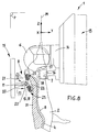
- la figure 8 est une vue d'élévation transversale d'une installation pour la découpe de carcasse analogue à celle de la figure 1 à une échelle agrandie, illustrant la mise en position de l'organe de coupe, ainsi que des organes de guidage respectivement interne et externe, préalablement à la découpe d'une carcasse ; la partie de la carcasse destinée à être découpée est représentée en hachures ; cette figure illustre l'installation selon un mode de réalisation où l'organe de guidage externe est indépendant de l'organe de coupe et de l'organe de guidage interne ;
- la figure 9 est une vue d'élévation transversale de l'installation de la figure 8 illustrant la phase de découpe de la carcasse ; l'organe de guidage interne est en appui sur la face dorsale interne de la carcasse, tandis que l'organe de guidage externe est en appui sur la face dorsale externe de la carcasse ;et
- la figure 10 est une vue d'élévation transversale d'une
installation pour la découpe de carcasses analogue à
celle des figures 8
et 9, selon un mode de réalisation où l'organe de guidage externe est porté par une poutre qui porte également l'organe de coupe et l'organe de guidage interne.
- Figure 1 is a transverse elevation view of an installation for cutting suspended carcasses of slaughter animals illustrating the cutting of a carcass moving between a cutting assembly and a support assembly comprising a pressing guide device on the outer dorsal side of the carcass and moving along the spine of the carcass; the guide device is fixed to the end of a transverse arm;
- Figure 2 is a partially exploded perspective view of the guide device of Figure 1;
- Figure 3 is a longitudinal elevation view of the guide device of Figure 2;
- Figure 4 is a partial sectional view of the guide device along the line IV-IV of Figure 3;
- Figure 5 is a sectional view of the guide device along the line VV of Figure 3, attached to the end of the transverse arm illustrated in Figure 1, also partially shown in section;
- Figure 6 is a partial longitudinal elevation view of the installation of Figure 1, illustrating a carcass on the outer dorsal face of which moves a guide device similar to that of Figures 2 to 5;
- Figure 7 is a sectional view of a carcass on which is supported a guide device, according to line VII-VII of Figure 6;
- FIG. 8 is a transverse elevation view of an installation for cutting the carcass similar to that of FIG. 1 on an enlarged scale, illustrating the positioning of the cutting member, as well as of the guide members respectively internal and external, prior to the cutting of a carcass; the part of the carcass intended to be cut is represented by hatching; this figure illustrates the installation according to an embodiment where the external guide member is independent of the cutting member and the internal guide member;
- Figure 9 is a transverse elevation view of the installation of Figure 8 illustrating the carcass cutting phase; the internal guide member bears on the internal dorsal face of the carcass, while the external guide member bears on the external dorsal face of the carcass; and
- Figure 10 is a transverse elevation view of an installation for cutting carcasses similar to that of Figures 8 and 9, according to an embodiment where the external guide member is carried by a beam which also carries the cutter and internal guide member.
On décrit à présent l'invention selon des modes de réalisation particuliers donnés à titre d'exemples non limitatifs.The invention is now described according to modes of particular achievements given as examples not limiting.
Sur la figure 1 est représentée une installation 1 pour la
découpe par sciage de carcasses 2 d'animaux de boucherie
suspendues par les pattes arrière à un transporteur 3 à
défilement continu ou discontinu.In Figure 1 is shown an
Le transporteur 3 achemine les carcasses 2 selon une
direction X longitudinale, tandis que les carcasses 2
suspendues définissent une direction Z d'élévation
perpendiculaire à la direction X longitudinale.The transporter 3 routes the
Les directions longitudinale X et d'élévation Z, représentées sur la figure 1, forment ensemble un plan dit médian M dans lequel sont déplacées les carcasses 2.The longitudinal X and elevation Z directions, shown in Figure 1, together form a so-called plane median M in which the carcasses are moved 2.
Une direction transversale Y, également représentée sur la figure 1, est perpendiculaire aux directions longitudinale X et d'élévation Z de sorte qu'ensemble ces trois directions X, Y, Z forment un repère orthogonal direct, par rapport auquel est effectuée la présente description.A transverse direction Y, also shown in the Figure 1, is perpendicular to the longitudinal directions X and Z elevation so that together these three directions X, Y, Z form a direct orthogonal coordinate system, by report in which this description is made.
Les termes « avant », « arrière » sont définis par rapport à la direction Y transversale, tandis que les termes « sur », « sous », « dessus », « dessous », « haut », « bas » sont définis par rapport à la direction Z d'élévation. The terms "front", "rear" are defined in relation to to the transverse Y direction, while the terms "On", "under", "above", "below", "top", "Low" are defined with respect to the Z direction elevation.
Dans la suite de la description, on considère une unique
carcasse 2 destinée à subir au moins une opération de
découpe par sciage selon un plan de coupe P d'élévation
transversale, sensiblement confondu avec le plan de
symétrie de la carcasse 2, dans lequel s'étend la colonne
vertébrale 4 de cette dernière.In the following description, we consider a
Le transporteur 3 peut être un convoyeur de forme et de
construction appropriées, permettant de suspendre la
carcasse 2 par l'intermédiaire d'une suspente 5 tel qu'un
tinet à deux branches aux extrémités desquelles les pattes
arrières de la carcasse 2 sont accrochées.The conveyor 3 can be a conveyor of shape and
suitable construction, allowing suspension of the
Pour réaliser la découpe de cette carcasse 2, l'installation 1 comprend :
- un organe de
coupe 6 apte à se déplacer suivant le plan de coupe P, pour fendre la carcasse 2 au moins en partie ; - un organe de guidage
interne 7 situé sous l'organe decoupe 6, apte à être appliqué contre uneface dorsale interne 8 de la carcasse 2 ; et - un organe de guidage externe 9 apte à être appliqué, à
l'encontre de l'organe de guidage
interne 7, contre uneface dorsale externe 10 de la carcasse 2.
- a cutting
member 6 able to move along the cutting plane P, to split thecarcass 2 at least in part; - an
internal guide member 7 located under the cuttingmember 6, capable of being applied against an internaldorsal face 8 of thecarcass 2; and - an
external guide member 9 capable of being applied, against theinternal guide member 7, against an externaldorsal face 10 of thecarcass 2.
La suspension de la carcasse 2 est telle qu'elle présente
sa face ventrale et sa face dorsale interne 8 à l'organe de
coupe 6 et à l'organe de guidage interne 7, tandis qu'elle
présente sa face dorsale 10 à l'organe externe 9.The suspension of the
L'organe de guidage externe 9 comprend un bras mobile 11 à
une extrémité libre duquel est monté pivotant un dispositif
de guidage externe 12, tandis que l'organe de coupe 6 et
l'organe de guidage interne 7 sont portés par un même
ensemble dit de coupe 13.The
L'ensemble de coupe 13 comprend une poutre 14 étendue
transversalement et portant l'organe de coupe 6.The cutting
Selon un premier mode de réalisation illustré sur les
figures 1, 8 et 9, l'organe de guidage externe 9 est porté
par un ensemble dit de guidage externe 15 indépendant de
l'ensemble de coupe 13.According to a first embodiment illustrated on the
Figures 1, 8 and 9, the
Selon ce mode de réalisation, le bras mobile 11 est
susceptible d'être animé, par un organe moteur non
représenté tel qu'un vérin hydraulique, pneumatique ou
analogue, d'un déplacement selon la flèche f1 telle
qu'illustrée à la figure 1, pour que le dispositif de
guidage externe 12 soit appuyé contre la face dorsale
externe 10 de la carcasse 2, ou inversement selon la flèche
f2 pour que le dispositif de guidage externe 12 libère
cette face dorsale externe 10.According to this embodiment, the
Selon un deuxième mode de réalisation, illustré sur la
figure 10, l'organe de guidage externe 9 est porté par
l'ensemble de coupe 13 ; par exemple la poutre 14 portant
l'organe de coupe 6 porte également le bras 11 mobile,
monté pivotant sur la poutre 14, dans un plan d'élévation
transversale.According to a second embodiment, illustrated on the
Figure 10, the
Selon ce mode de réalisation, le bras mobile 11 peut être
animé d'un mouvement de rotation selon la flèche f3
représentée sur la figure 10.According to this embodiment, the
L'organe de coupe 6 peut être une scie circulaire, tandis
que l'organe de guidage interne 7 peut comprendre un
palonnier 16 portant deux galets de guidage 17, 18
coopérant avec la face dorsale interne 8 de la carcasse 2
lors de la découpe de celle-ci (figures 1, 8, 9 et 10).The cutting
Le procédé de découpe de la carcasse 2 se déroule de la façon suivante :
- on introduit l'organe de
coupe 6 entre les pattes arrière de la carcasse 2 ; - on applique contre la
face dorsale interne 8 de la carcasse 2 l'organe de guidageinterne 7 ; - on applique contre la
face dorsale externe 10 l'organe de guidage externe 9 à l'encontre de l'organe de guidageinterne 7 ; - on mettre en fonction l'organe de
coupe 6 ; lorsque celui-ci est une scie circulaire, on entraíne en rotation cette scie circulaire ; - on déplace l'ensemble de
coupe 13 et l'ensemble de guidage externe 15 selon le plan de coupe P, depuis le haut vers le bas.
- the cutting
member 6 is introduced between the rear legs of thecarcass 2; - the
internal guide member 7 is applied against the internaldorsal face 8 of thecarcass 2; - the
external guide member 9 is applied against the externaldorsal face 10 against theinternal guide member 7; - the cutting
member 6 is put into operation; when the latter is a circular saw, this circular saw is rotated; - the cutting
assembly 13 and theexternal guide assembly 15 are moved along the cutting plane P, from the top to the bottom.
Les organes de guidage interne 7 et externe 9 agissent, au
fur et à mesure de leur progression le long de la colonne
vertébrale 4 de la carcasse 2, de manière à faire coïncider
le plan de coupe P et le plan de symétrie de la colonne
vertébrale 4 pour obtenir une division de la carcasse 2 en
deux demi-carcasses sensiblement égales.The internal 7 and external 9 guide members act, at the
as they progress along the
La conformation de la face dorsale externe 10 de la
carcasse 2 évolue le long de la colonne vertébrale 4. Cette
évolution a une influence négative sur la qualité du
guidage assuré par l'organe de guidage externe 9.The conformation of the external
Par ailleurs, la découpe ayant lieu dans une atmosphère
chargée de vapeur d'eau et de graisse, la face dorsale
externe de la carcasse se révèle glissante, ce qui nuit
également au positionnement de l'organe de guidage externe
9, et au maintien de la carcasse par ce dernier.Furthermore, the cutting taking place in an atmosphere
loaded with water vapor and fat, the dorsal side
carcass is slippery, which harms
also to the positioning of the
Afin de remédier à ces inconvénients, le procédé de découpe
décrit ci-dessus prévoit en outre de pincer la face dorsale
externe 10 de la carcasse 2 pour assurer un maintien ferme
de la carcasse lors de sa découpe, en appliquant contre la
face dorsale externe 10 de la carcasse 2 le dispositif de
guidage externe 12 et en déplaçant celui-ci selon le plan
de coupe P.In order to overcome these drawbacks, the cutting process
described above further provides for pinching the dorsal side
external 10 of the
Ce dispositif 12, que l'on décrit à présent en détail en
référence aux figures 2 à 7, est prévu pour assurer ce
pincement lors de son déplacement le long du plan de coupe
P.This
Le dispositif de guidage 12 se présente sous la
forme d'un palonnier 19, monté pivotant sur une partie
extrême libre 21 du bras mobile 11 formant chape, au moyen
d'un moyeu 20.The
Ce palonnier 19 comprend :
un châssis 22 qui comprend uneface interne 23 destinée à être orientée vers laface dorsale externe 10 de la carcasse 2, ainsi qu'uneface externe 24 opposée à laface interne 23 et par exemple sensiblement parallèle à celle-ci ; et- au moins une paire 25 de galets 26, 27 fous montés sur
le châssis 22 autour d'axes de
rotation
- a
frame 22 which comprises aninternal face 23 intended to be oriented towards the externaldorsal face 10 of thecarcass 2, as well as anexternal face 24 opposite to theinternal face 23 and for example substantially parallel thereto; and - at least one
pair 25 ofidler rollers chassis 22 around axes ofrotation
Selon un mode de réalisation, le châssis 22 présente une
symétrie par rapport à un plan noté S qui, lorsque le
palonnier 19 est appliqué contre la face dorsale externe 10
de la carcasse 2, est sensiblement confondu avec le plan P
de coupe.According to one embodiment, the
Le moyeu 20 est fixé à
demeure sur la face externe 24 du châssis 22.The
Le palonnier 19 peut pivoter autour d'un axe de rotation R
longitudinal, confondu avec l'axe du moyeu 20, et
sensiblement perpendiculaire au plan S de symétrie du
châssis 22.The
Le moyeu 20 se présente, selon un mode de réalisation
illustré sur les figures, sous la forme d'un cylindre percé
d'un alésage 30 d'axe R.The
Le moyeu comprend une partie médiane 31 ainsi que deux
parties extrêmes 32, 33 dont le diamètre est inférieur à
celui de la partie médiane 31, dont elles sont séparées par
deux épaulements 34, 35.The hub includes a
Un arbre 36 est introduit dans l'alésage 30 et associé à
ses deux extrémités à une chape 37 dont est pourvu la
partie extrême libre 21 du bras mobile 11.A
Ce montage permet au moyeu 20, et donc au palonnier, de
pivoter autour de son axe R par rapport au bras mobile 11.This assembly allows the
Afin d'asservir la position angulaire du palonnier 19 par
rapport au bras mobile 11, il peut être prévu au moins un
organe de rappel élastique 38 tel qu'un ressort de torsion,
disposé entre le palonnier 19 et le bras mobile 11. In order to control the angular position of the
Par exemple, le dispositif de guidage externe 12 comprend
deux ressorts hélicoïdaux 38 de traction emmanchés chacun
sur une partie extrême 32, 33 du moyeu 20.For example, the
Chaque ressort 38 comprend par exemple deux saillies
terminales 39, 40, dont l'une 39 est enfilée dans une
fenêtre oblongue 41 ménagée dans une bague 42, 43 emmanchée
sur la partie extrême 32, 33 du moyeu 20, contre
l'épaulement 34, 35 correspondant.Each
L'autre saillie terminale 40 est quant à elle enfilée dans
un trou 44 percé dans la chape 37 du bras 11.The
La bague 42, 43 est maintenue fixe en rotation par exemple
par l'intermédiaire d'une clavette, une goupille, ou
analogue.The
Selon un mode de réalisation illustré sur la figure 5, la
bague 42, 43 est maintenue fixe en rotation sur le moyeu 20
au moyen d'une vis sans tête 45 qui traverse radialement la
bague 42, 43 et appuie sur la surface extérieure du moyeu
20, ce qui permet un réglage de la position angulaire du
palonnier 19 par rapport au bras mobile 11.According to an embodiment illustrated in FIG. 5, the
On décrit à présent le châssis 22. Par chassis on entend
tout type de structure de support des galets 26, 27.The
Selon un mode de réalisation, le châssis 22 comprend par
ailleurs une paire 46 de branches 46a, 46b étendues de part
et d'autre du plan S de symétrie.According to one embodiment, the
Selon un mode de réalisation illustré sur la figure 5
notamment, le châssis 22 est pourvu de deux paires de
branches : une paire supérieure 46 de branches 46a, 46b, et
une paire inférieure 47 de branches 47a, 47b, qui forment
ensemble une croix s'étendant de part et d'autre du moyeu
20 et de part et d'autre du plan S de symétrie.According to an embodiment illustrated in Figure 5
in particular, the
Les paires 46, 47 de branches 46a, 46b, 47a, 47b portent
alors chacune une paire 25 de galets 26, 27 disposés
sensiblement symétriquement par rapport au plan de symétrie
S.The
Chaque branche 46a, 46b, 47a, 47b présente une partie
extrême libre 48 sur laquelle est monté un galet 26, 27,
qui peut pivoter par rapport à la branche autour de son axe
de rotation 28, 29.Each branch 46a, 46b, 47a, 47b has a part
extreme free 48 on which a
Selon une variante, le châssis 22 se présente sous la forme
d'une rampe étendue sensiblement selon le plan de coupe P.
Cette rampe est par exemple pourvue d'une pluralité de
paires de branches portant chacune un galet. Cette rampe
peut être articulée pour pouvoir s'adapter au contour de la
colonne vertébrale 4 de la carcasse 2.According to a variant, the
Par ailleurs, chaque galet 26, 27 présente une surface
extérieure 49 destinée à être appuyée sur la face dorsale
externe 10 de la carcasse 2 lorsque le dispositif 12 est
appliqué contre cette face dorsale 10.Furthermore, each
Cette surface 49 présente une symétrie de révolution autour
de l'axe de rotation 28, 29 du galet 26, 27.This
Selon un mode de réalisation illustré sur les figures,
cette surface 49 est tronconique. Le galet 26, 27 présente
une surface de base 50 et une surface de sommet 51
circulaires, le diamètre de la surface de base 50 étant
supérieur au diamètre de la surface de sommet 51. According to an embodiment illustrated in the figures,
this
Selon un mode de réalisation, le galet 26, 27 est fixé à la
branche 46a, 46b, 47a, 47b de manière que sa surface de
base 50 soit tournée vers le châssis 22, la surface de
sommet 51 étant localisée à distance du châssis 22.According to one embodiment, the
Chaque galet 26, 27 présente une conicité dont l'ouverture
angulaire, notée α, est choisie en fonction de la
conformation de la face dorsale 10 des carcasses 2 à
découper.Each
L'ouverture angulaire α est par exemple comprise entre 5° et 120°. Selon un mode de réalisation illustré sur les figures 4 et 7, cette ouverture angulaire α est de 70° environ.The angular opening α is for example between 5 ° and 120 °. According to an embodiment illustrated on the Figures 4 and 7, this angular opening α is 70 ° about.
Les galets 26, 27 sont par exemple interchangeables afin de
permettre une adéquation du dispositif de guidage 12 avec
la conformation des différents types de carcasses 2 à
découper, ou afin de changer tout galet présentant une
usure prononcée nuisant au maintien ferme de la carcasse 2.The
A cet effet, la fixation des galets 26, 27 au châssis 22
peut être réalisée au moyen de vis et de manchons
cylindriques (figure 4).To this end, the fixing of the
En outre, les axes de rotation 28, 29 respectifs des galets
26, 27 d'une même paire 25 forment ensemble un « V » dont
l'ouverture est orientée dans la même direction que la face
interne 23 du châssis 22.In addition, the respective axes of
Cette caractéristique distingue le dispositif de guidage 12
des dispositifs classiques, dont les galets, généralement
de forme tronconique pour s'adapter à la forme bombée de la
face dorsale externe de la carcasse, tournent autour d'axes
perpendiculaires au plan de coupe.This characteristic distinguishes the
De la sorte, le mouvement circulaire d'un point situé à la surface du galet en contact avec la carcasse s'effectue dans un plan parallèle au plan de coupe, la force d'appui exercée par le galet étant également parallèle au plan de coupe, ce qui présente l'inconvénient de ne pas assurer un maintien ferme de la carcasse.In this way, the circular movement of a point located at the surface of the roller in contact with the carcass takes place in a plane parallel to the cutting plane, the bearing force exerted by the roller also being parallel to the plane of cut, which has the disadvantage of not ensuring a firm support of the carcass.
Par contre, grâce à l'inclinaison des galets 26, 27, un
point situé sur la surface extérieure 49 décrit, lors de la
rotation du galet 26, 27, un mouvement circulaire dans un
plan dit de guidage G sensiblement perpendiculaire à l'axe
28, 29 du galet, de sorte que les forces d'appui -
illustrées sur la figure 7 par les flèches F1, F2 -
exercées par les galets 26, 27 d'une même paire 25 sur la
face dorsale externe 10 de la carcasse 2 sont convergentes
et dirigées vers le plan de coupe P.On the other hand, thanks to the inclination of the
La combinaison des forces d'appui F1 et F2 provoque,
lorsque les galets 26, 27 roulent sur la face dorsale
externe 10 dans un sens indiqué par les flèches f4
indiquées sur la figure 6, un pincement de la face dorsale
externe 10 qui permet un maintien ferme de la carcasse 2 et
évite son pivotement autour de la colonne vertébrale 4 lors
de sa découpe. L'effet technique serait au moins en partie
dû aux effets de vitesses de rotation variant sur les
galets tronconiques.The combination of the support forces F1 and F2 causes,
when the
L'angle, noté β, formé par les axes de rotation 28, 29 des
galets 26, 27 d'une même paire 25 est par exemple compris
entre 40° et 120°. The angle, denoted β, formed by the axes of
Selon un mode de réalisation illustré sur les figures 2, 4 et 7, l'angle β est sensiblement égal à 60°.According to an embodiment illustrated in Figures 2, 4 and 7, the angle β is substantially equal to 60 °.
En outre, chaque galet 26, 27 peut comprendre au moins une
gorge 52 ménagée dans sa surface extérieure 49.In addition, each
Cette gorge 52 présente par exemple une symétrie de
révolution autour de l'axe de rotation 28, 29 du galet 26,
27.This
Cette gorge peut être de section rectangulaire, carrée,
pseudo-rectangulaire, pseudo-carrée, ou encore semi-circulaire
dans un plan contenant l'axe 28, 29 du galet 26,
27.This groove can be rectangular, square,
pseudo-rectangular, pseudo-square, or even semi-circular
in a plane containing the
Selon un mode de réalisation illustré sur les figures,
chaque galet 26, 27 comprend une pluralité de gorges 52
coaxiales, telles que celle qui vient d'être décrite,
espacées les unes des autres, ménagées dans la surface
extérieure 50 du galet 26, 27.According to an embodiment illustrated in the figures,
each
Ces gorges 52 confèrent aux galets 26, 27 des propriétés
anti-dérapantes permettant d'améliorer le maintien de la
carcasse 2 par le dispositif de guidage 12.These
Ces gorges 52 permettent notamment l'évacuation, lors du
roulement des galets 26, 27 sur la face dorsale externe 10
de la carcasse 2, des liquides présents sur celle-ci, à la
manière du relief d'un pneu de véhicule évacuant l'eau
présente sur la chaussée.These
En ce qui concerne les matériaux utilisés, le châssis 22
peut être réalisé au moins partiellement en métal, par
exemple en acier, tandis que les galets 26, 27 peuvent être
réalisés dans un matériau polymère synthétique tel qu'une
fibre polyamide aisée à mouler et/ou à usiner.Regarding the materials used, the
Le dispositif de guidage 12 peut également comprendre des
moyens de réglage de l'angle entre les axes de rotation 28,
29 des galets 26, 27 d'une même paire 25 pour s'adapter à
la conformation de la face dorsale externe 10 de la
carcasse 2.The
Grâce à l'inclinaison des galets décrite, le palonnier est efficace même lorsqu'une opération de prédécoupe est effectuée sur la face dorsale. En particulier le palonnier permet un recentrage des chairs et des apophyses qui précède la découpe par la lame de scie. Il est ainsi efficace même si l'on a retiré avant la découpe de la carcasse en demi carcasses une zone 53 (figure 7), pour la fabrication par exemple de bacon canadien ou de lonzo italien.Thanks to the inclination of the rollers described, the lifter is effective even when a precut operation is performed on the dorsal side. In particular the lifter allows a refocusing of the flesh and the processes which precedes cutting with the saw blade. It is so effective even if you removed before cutting the carcass in half carcasses an area 53 (figure 7), for the making, for example, Canadian bacon or lonzo Italian.
Par ailleurs on comprend que l'utilisation d'axes inclinés peut s'appliquer à des châssis de dispositif de guidage externe très variés, mobiles embarqués sur la tête de coupe ou sur une colonne indépendante ,ou sur points fixes.We also understand that the use of inclined axes can be applied to guiding device chassis very varied external, mobile on the cutting head or on an independent column, or on fixed points.
Claims (13)
- A guidance device able to bear on the external dorsal face (10) of the carcass (2) of an animal, when this is being cut, the said device (12) comprising:the said device (12) being characterised in that it is in the form of a bar (19), comprising a hub (20) permanently fixed to the external face (24) of the frame (22), the frame (22) comprising at least one pair (46) of arms (46a, 46b), on each of which a roller (26, 27) is pivotally mounted.a frame (22) which comprises an internal face (23) intended to be oriented towards the external dorsal face (10) of the carcass (2), and an external face (24) opposite to the said internal face (23); andat least one pair (25) of loose rollers (26, 27) mounted on the frame (22) about axes of rotation (28, 29), each roller (26, 27) having an external surface (49) able to be pressed against the external dorsal face (10) of the carcass (2), the axes of rotation (28, 29) of the rollers (26, 27) in one and the same pair (25) forming together a V whose opening is oriented in the same direction as the internal face (23) of the chassis (22),
- A guidance device according to Claim 1, characterised in that each roller (26, 27) is in the shape of a truncated cone of revolution whose axis is substantially merged with the axis of rotation (28, 29) of the roller (26, 27) and whose base (50) is turned towards the frame (22).
- A guidance device according to Claim 1 or Claim 2, characterised in that each roller (26, 27) comprises at least one groove (52) provided in the external surface (49) of the roller (26, 27), this groove (62) having symmetry of revolution about the axis of rotation (28, 29) of the roller (26, 27).
- A guidance device according to one of Claims 1 to 3, characterised in that each roller (26, 27) comprises a plurality of coaxial grooves (52) spaced apart from one another, provided in the external surface (49) of the roller (26, 27), each having symmetry of revolution about the axis of rotation (28, 29) of the roller (26, 27).
- A guidance device according to one of Claims 1 to 4, characterised in that the angle (β) formed by the axes of rotation (28, 29) of the rollers (26, 27) in one and the same pair (25) is between 60° and 140°.
- A guidance device according to one of Claims 1 to 5, characterised in that the said rollers (26, 27) are produced from a synthetic polymer material.
- A device according to one of Claims 1 to 6, characterised in that the frame (22) comprises two pairs (46, 47) of arms (46a, 46b; 47a, 47b) disposed in a cross, a roller (26, 27) being pivotally mounted on each arm (46a, 46b; 47a, 47b).
- An installation for cutting suspended carcasses (2) of butchery animals, comprising:characterised in that the external guidance member (9) comprises a guidance device (12) according to one of Claims 1 to 7.a cutting member (6) able to move in a so-called cutting plane (P) in order to at least partly cut a carcass (2);an internal guidance member (9) situated under the cutting member (6), able to be applied against an internal dorsal face (8) of the carcass (2); andan external guidance member (9) able to be applied, counter to the internal guidance member (9), against an external dorsal face (10) of the carcass (2),
- An installation according to Claim 8, characterised in that the said external guidance device (12) is pivotally mounted on a movable arm (11) carried by a beam (14) which also carries the cutting member (6).
- An installation according to Claim 8, characterised in that the said external guidance device (12) is pivotally mounted on a movable arm (11) independent of the cutting member (6).
- An installation according to Claim 9 or Claim 10, characterised in that the said external guidance device (12) forms a bar (19) pivotally mounted on the movable arm (11) by means of a hub (20), the said device (12) being able to pivot with respect to the axis of the hub (20).
- An installation according to one of Claims 8 to 10, characterised in that the said external guidance device (12) comprises an elastic return member (38) able to slave the angular position of the external guidance device (12) with respect to the movable arm (11).
- A method of cutting butchery animal carcasses (2) which comprises the steps making provision for:the said method being characterised in that it also comprises a step making provision for gripping the external dorsal face (10) of the carcass (2) in order to ensure that it is held whilst it is being cut, by applying against the external dorsal face (10) of the carcass (2) a guidance device (12) according to one of Claims 1 to 7 and moving it along the said cutting plane (P).introducing a cutting member (6) through the open ventral side of the carcass (2);applying an internal guidance member (9) against an internal dorsal face (8) of the carcass (2);applying an external guidance member (9) against an external dorsal face (10) of the carcass (2) counter to the internal guidance member (8) ;starting up the cutting member (6) ;moving the assembly along a cutting plane (P) ;
Applications Claiming Priority (2)
| Application Number | Priority Date | Filing Date | Title |
|---|---|---|---|
| FR0002045A FR2805129B1 (en) | 2000-02-18 | 2000-02-18 | GUIDANCE DEVICE FOR CUTTING CARCASES OF BUTCHING ANIMALS, INSTALLATION FOR CUTTING CARCASSES COMPRISING SUCH A DEVICE, AND METHOD FOR CUTTING CARCASES |
| FR0002045 | 2000-02-18 |
Publications (3)
| Publication Number | Publication Date |
|---|---|
| EP1125501A2 EP1125501A2 (en) | 2001-08-22 |
| EP1125501A3 EP1125501A3 (en) | 2001-10-10 |
| EP1125501B1 true EP1125501B1 (en) | 2003-05-21 |
Family
ID=8847146
Family Applications (1)
| Application Number | Title | Priority Date | Filing Date |
|---|---|---|---|
| EP01400126A Expired - Lifetime EP1125501B1 (en) | 2000-02-18 | 2001-01-17 | Guiding device for splitting carcasses, apparatus for splitting carcasses comprising such device and method for splitting carcasses |
Country Status (5)
| Country | Link |
|---|---|
| EP (1) | EP1125501B1 (en) |
| AT (1) | ATE240652T1 (en) |
| DE (1) | DE60100277T2 (en) |
| DK (1) | DK1125501T3 (en) |
| FR (1) | FR2805129B1 (en) |
Families Citing this family (5)
| Publication number | Priority date | Publication date | Assignee | Title |
|---|---|---|---|---|
| FR2870090B1 (en) * | 2004-05-17 | 2006-08-04 | Durand Internat Sa | EXTERNAL GUIDING SYSTEM OF A CARCASS COMPRISING A DEVICE FOR ANGULAR LIMITATION |
| FR2874790B1 (en) | 2004-09-07 | 2006-11-17 | Durand Internat Soc Par Action | GUIDING ROLLS FOR ANIMAL CARCASE SLITTING INSTALLATION |
| DE202008008813U1 (en) | 2008-05-09 | 2008-10-16 | Banss Schlacht- und Fördertechnik GmbH | Arrangement for splitting a slaughter animal |
| ES2702423A1 (en) * | 2017-08-31 | 2019-02-28 | Aira Robotics S L | DEVICE FOR FRONT AND DORSAL CUTTING OF A PORK CASE (Machine-translation by Google Translate, not legally binding) |
| ES2926000A1 (en) * | 2021-04-09 | 2022-10-20 | Aira Robotics S L | DEVICE FOR CUTTING IN HALF AN ANIMAL AND ROBOT CARCASS INCORPORATING SAID CUTTING DEVICE (Machine-translation by Google Translate, not legally binding) |
Family Cites Families (4)
| Publication number | Priority date | Publication date | Assignee | Title |
|---|---|---|---|---|
| DE1189404B (en) * | 1960-02-19 | 1965-03-18 | Antonin Koettner | Device for halving slaughtered cattle in a hanging position |
| FR2535944A1 (en) | 1982-11-15 | 1984-05-18 | Schlumberger Cie N | AUTOMATIC MACHINE FOR SCREWING BUTCHER ANIMALS, IN PARTICULAR PIGS |
| DE3247588C2 (en) * | 1982-12-22 | 1986-11-06 | Banss Kg Maschinenfabrik, 3560 Biedenkopf | Device for cutting carcases in half by sawing |
| FR2747538B1 (en) | 1996-04-18 | 1998-06-05 | Durand International | METHOD AND DEVICE FOR BACK GUIDING FOR SLITTING A CARCASS OF BEEF ANIMALS |
-
2000
- 2000-02-18 FR FR0002045A patent/FR2805129B1/en not_active Expired - Fee Related
-
2001
- 2001-01-17 EP EP01400126A patent/EP1125501B1/en not_active Expired - Lifetime
- 2001-01-17 DE DE60100277T patent/DE60100277T2/en not_active Expired - Fee Related
- 2001-01-17 DK DK01400126T patent/DK1125501T3/en active
- 2001-01-17 AT AT01400126T patent/ATE240652T1/en not_active IP Right Cessation
Also Published As
| Publication number | Publication date |
|---|---|
| FR2805129A1 (en) | 2001-08-24 |
| DE60100277T2 (en) | 2004-04-01 |
| DK1125501T3 (en) | 2003-09-22 |
| DE60100277D1 (en) | 2003-06-26 |
| EP1125501A3 (en) | 2001-10-10 |
| FR2805129B1 (en) | 2005-02-18 |
| ATE240652T1 (en) | 2003-06-15 |
| EP1125501A2 (en) | 2001-08-22 |
Similar Documents
| Publication | Publication Date | Title |
|---|---|---|
| CA2185820C (en) | Process and apparatus for the splitting of a meat animal carcass | |
| FR2596948A1 (en) | APPARATUS FOR EBRANKING THE TRUNKS OF TREES | |
| FR2496539A1 (en) | KNIFE HOLDER WITH HYDRAULIC CONTROL | |
| EP1125501B1 (en) | Guiding device for splitting carcasses, apparatus for splitting carcasses comprising such device and method for splitting carcasses | |
| EP0377542B1 (en) | Adjustable internal guiding-element for a device for splitting carcasses of slaughtered animals, and splitting method therefor | |
| FR2719516A1 (en) | Tooling for the shaping of cylindrical spans with diameter control of the spans. | |
| EP0801900B1 (en) | Method and means for dorsal guiding in carcass splitting | |
| EP0300940B1 (en) | Method and means for deboning a carcass hind quarter | |
| EP0624431A1 (en) | Belt finishing apparatus for cylindrical workpieces | |
| LU82350A1 (en) | MACHINE FOR SLENDING SLABS BY OXY CUTTING | |
| FR2794612A1 (en) | Cutting head, for pruning trees and shrubs, comprises body, with gripping arms, cutter and drive wheels, made of metal core with outer elastic layer carrying series of chains | |
| FR2567500A1 (en) | TAPE MATERIAL WINDING APPARATUS | |
| CA2639355A1 (en) | Drive unit of a splitting tool caddy of a carcass splitting machine | |
| FR2891987A1 (en) | Tool for leveling bases of Christmas trees after felling has cutter wheels mounted on swiveling jaws which can be positioned around trunk, tool being attached to circular guide, allowing cuts to be made around full circumference of trunk | |
| CA2192227A1 (en) | Automatic device for separating the feet from hog carcasses | |
| FR2655285A1 (en) | MACHINE TO AFFECT THE KNIVES. | |
| FR2870090A1 (en) | External guidance system for suspended animal carcasses in an abattoir comprises pivoted frame with upper and lower pairs of rollers | |
| FR3031688A1 (en) | MACHINE CUTTING OR SLICING MULTI-KNIVES | |
| CA2890464A1 (en) | Machine and method for reducing parts of tyres to pieces at the end of life | |
| EP3047722B1 (en) | Improved cutting tool with anvil | |
| FR2919473A1 (en) | Carcass e.g. pig carcass, sawing method for carcass saw installation, involves maintaining front part of cutting edge of saw blade in active position when blade is displaced from upper outer position to lower outer portion | |
| FR2884746A1 (en) | Knife blade`s edge sharpening device for agro-food industry laboratory , has two pairs of curved rods integrated, by their lower end parts, to shafts whose distal end parts comprise squared section complementary to central holes of wheels | |
| FR2506271A1 (en) | V=section conveyor with flat band sides for animals in abattoir etc. - has V width adjustment which alters bottom width more than top width | |
| FR2660837A2 (en) | Method for skinning the head and limbs of slaughterhouse animals, and device for implementing it | |
| EP0722849B1 (en) | Castor with adjustable locking of steering |
Legal Events
| Date | Code | Title | Description |
|---|---|---|---|
| PUAI | Public reference made under article 153(3) epc to a published international application that has entered the european phase |
Free format text: ORIGINAL CODE: 0009012 |
|
| AK | Designated contracting states |
Kind code of ref document: A2 Designated state(s): AT BE CH CY DE DK ES FI FR GB GR IE IT LI LU MC NL PT SE TR |
|
| AX | Request for extension of the european patent |
Free format text: AL;LT;LV;MK;RO;SI |
|
| PUAL | Search report despatched |
Free format text: ORIGINAL CODE: 0009013 |
|
| AK | Designated contracting states |
Kind code of ref document: A3 Designated state(s): AT BE CH CY DE DK ES FI FR GB GR IE IT LI LU MC NL PT SE TR |
|
| AX | Request for extension of the european patent |
Free format text: AL;LT;LV;MK;RO;SI |
|
| 17P | Request for examination filed |
Effective date: 20011127 |
|
| 17Q | First examination report despatched |
Effective date: 20020225 |
|
| AKX | Designation fees paid |
Free format text: AT BE CH CY DE DK ES FI FR GB GR IE IT LI LU MC NL PT SE TR |
|
| GRAH | Despatch of communication of intention to grant a patent |
Free format text: ORIGINAL CODE: EPIDOS IGRA |
|
| GRAH | Despatch of communication of intention to grant a patent |
Free format text: ORIGINAL CODE: EPIDOS IGRA |
|
| GRAA | (expected) grant |
Free format text: ORIGINAL CODE: 0009210 |
|
| AK | Designated contracting states |
Designated state(s): AT BE CH CY DE DK ES FI FR GB GR IE IT LI LU MC NL PT SE TR |
|
| PG25 | Lapsed in a contracting state [announced via postgrant information from national office to epo] |
Ref country code: IE Free format text: LAPSE BECAUSE OF NON-PAYMENT OF DUE FEES Effective date: 20030521 Ref country code: IT Free format text: LAPSE BECAUSE OF FAILURE TO SUBMIT A TRANSLATION OF THE DESCRIPTION OR TO PAY THE FEE WITHIN THE PRESCRIBED TIME-LIMIT;WARNING: LAPSES OF ITALIAN PATENTS WITH EFFECTIVE DATE BEFORE 2007 MAY HAVE OCCURRED AT ANY TIME BEFORE 2007. THE CORRECT EFFECTIVE DATE MAY BE DIFFERENT FROM THE ONE RECORDED. Effective date: 20030521 Ref country code: TR Free format text: LAPSE BECAUSE OF FAILURE TO SUBMIT A TRANSLATION OF THE DESCRIPTION OR TO PAY THE FEE WITHIN THE PRESCRIBED TIME-LIMIT Effective date: 20030521 Ref country code: GB Free format text: LAPSE BECAUSE OF FAILURE TO SUBMIT A TRANSLATION OF THE DESCRIPTION OR TO PAY THE FEE WITHIN THE PRESCRIBED TIME-LIMIT Effective date: 20030521 Ref country code: AT Free format text: LAPSE BECAUSE OF FAILURE TO SUBMIT A TRANSLATION OF THE DESCRIPTION OR TO PAY THE FEE WITHIN THE PRESCRIBED TIME-LIMIT Effective date: 20030521 Ref country code: CY Free format text: LAPSE BECAUSE OF FAILURE TO SUBMIT A TRANSLATION OF THE DESCRIPTION OR TO PAY THE FEE WITHIN THE PRESCRIBED TIME-LIMIT Effective date: 20030521 Ref country code: FI Free format text: LAPSE BECAUSE OF FAILURE TO SUBMIT A TRANSLATION OF THE DESCRIPTION OR TO PAY THE FEE WITHIN THE PRESCRIBED TIME-LIMIT Effective date: 20030521 |
|
| REG | Reference to a national code |
Ref country code: GB Ref legal event code: FG4D Free format text: NOT ENGLISH |
|
| REG | Reference to a national code |
Ref country code: CH Ref legal event code: EP |
|
| REG | Reference to a national code |
Ref country code: IE Ref legal event code: FG4D Free format text: FRENCH |
|
| REF | Corresponds to: |
Ref document number: 60100277 Country of ref document: DE Date of ref document: 20030626 Kind code of ref document: P |
|
| PG25 | Lapsed in a contracting state [announced via postgrant information from national office to epo] |
Ref country code: GR Free format text: LAPSE BECAUSE OF FAILURE TO SUBMIT A TRANSLATION OF THE DESCRIPTION OR TO PAY THE FEE WITHIN THE PRESCRIBED TIME-LIMIT Effective date: 20030821 Ref country code: PT Free format text: LAPSE BECAUSE OF FAILURE TO SUBMIT A TRANSLATION OF THE DESCRIPTION OR TO PAY THE FEE WITHIN THE PRESCRIBED TIME-LIMIT Effective date: 20030821 Ref country code: SE Free format text: LAPSE BECAUSE OF FAILURE TO SUBMIT A TRANSLATION OF THE DESCRIPTION OR TO PAY THE FEE WITHIN THE PRESCRIBED TIME-LIMIT Effective date: 20030821 |
|
| PG25 | Lapsed in a contracting state [announced via postgrant information from national office to epo] |
Ref country code: ES Free format text: LAPSE BECAUSE OF FAILURE TO SUBMIT A TRANSLATION OF THE DESCRIPTION OR TO PAY THE FEE WITHIN THE PRESCRIBED TIME-LIMIT Effective date: 20030901 |
|
| REG | Reference to a national code |
Ref country code: DK Ref legal event code: T3 |
|
| GBV | Gb: ep patent (uk) treated as always having been void in accordance with gb section 77(7)/1977 [no translation filed] |
Effective date: 20030521 |
|
| REG | Reference to a national code |
Ref country code: IE Ref legal event code: FD4D Ref document number: 1125501E Country of ref document: IE |
|
| PG25 | Lapsed in a contracting state [announced via postgrant information from national office to epo] |
Ref country code: LU Free format text: LAPSE BECAUSE OF NON-PAYMENT OF DUE FEES Effective date: 20040117 |
|
| PG25 | Lapsed in a contracting state [announced via postgrant information from national office to epo] |
Ref country code: BE Free format text: LAPSE BECAUSE OF NON-PAYMENT OF DUE FEES Effective date: 20040131 Ref country code: MC Free format text: LAPSE BECAUSE OF NON-PAYMENT OF DUE FEES Effective date: 20040131 |
|
| PLBE | No opposition filed within time limit |
Free format text: ORIGINAL CODE: 0009261 |
|
| STAA | Information on the status of an ep patent application or granted ep patent |
Free format text: STATUS: NO OPPOSITION FILED WITHIN TIME LIMIT |
|
| 26N | No opposition filed |
Effective date: 20040224 |
|
| BERE | Be: lapsed |
Owner name: *DURAND INTERNATIONAL Effective date: 20040131 |
|
| PG25 | Lapsed in a contracting state [announced via postgrant information from national office to epo] |
Ref country code: CH Free format text: LAPSE BECAUSE OF NON-PAYMENT OF DUE FEES Effective date: 20050131 Ref country code: LI Free format text: LAPSE BECAUSE OF NON-PAYMENT OF DUE FEES Effective date: 20050131 |
|
| REG | Reference to a national code |
Ref country code: CH Ref legal event code: PL |
|
| PGFP | Annual fee paid to national office [announced via postgrant information from national office to epo] |
Ref country code: DK Payment date: 20080215 Year of fee payment: 8 |
|
| PGFP | Annual fee paid to national office [announced via postgrant information from national office to epo] |
Ref country code: DE Payment date: 20080207 Year of fee payment: 8 Ref country code: NL Payment date: 20080203 Year of fee payment: 8 |
|
| PGFP | Annual fee paid to national office [announced via postgrant information from national office to epo] |
Ref country code: FR Payment date: 20080131 Year of fee payment: 8 |
|
| NLV4 | Nl: lapsed or anulled due to non-payment of the annual fee |
Effective date: 20090801 |
|
| REG | Reference to a national code |
Ref country code: DK Ref legal event code: EBP |
|
| PG25 | Lapsed in a contracting state [announced via postgrant information from national office to epo] |
Ref country code: DE Free format text: LAPSE BECAUSE OF NON-PAYMENT OF DUE FEES Effective date: 20090801 |
|
| REG | Reference to a national code |
Ref country code: FR Ref legal event code: ST Effective date: 20091030 |
|
| PG25 | Lapsed in a contracting state [announced via postgrant information from national office to epo] |
Ref country code: NL Free format text: LAPSE BECAUSE OF NON-PAYMENT OF DUE FEES Effective date: 20090801 |
|
| PG25 | Lapsed in a contracting state [announced via postgrant information from national office to epo] |
Ref country code: FR Free format text: LAPSE BECAUSE OF NON-PAYMENT OF DUE FEES Effective date: 20090202 |
|
| PG25 | Lapsed in a contracting state [announced via postgrant information from national office to epo] |
Ref country code: DK Free format text: LAPSE BECAUSE OF NON-PAYMENT OF DUE FEES Effective date: 20090731 |