EP1125487A1 - Machine polyvalente de culture interpieds pour plantations d'arbres ou arbustes telles que vignes ou vergers - Google Patents
Machine polyvalente de culture interpieds pour plantations d'arbres ou arbustes telles que vignes ou vergers Download PDFInfo
- Publication number
- EP1125487A1 EP1125487A1 EP00430008A EP00430008A EP1125487A1 EP 1125487 A1 EP1125487 A1 EP 1125487A1 EP 00430008 A EP00430008 A EP 00430008A EP 00430008 A EP00430008 A EP 00430008A EP 1125487 A1 EP1125487 A1 EP 1125487A1
- Authority
- EP
- European Patent Office
- Prior art keywords
- multipurpose
- intercropping
- machine according
- tools
- arm
- Prior art date
- Legal status (The legal status is an assumption and is not a legal conclusion. Google has not performed a legal analysis and makes no representation as to the accuracy of the status listed.)
- Granted
Links
Images


Classifications
-
- A—HUMAN NECESSITIES
- A01—AGRICULTURE; FORESTRY; ANIMAL HUSBANDRY; HUNTING; TRAPPING; FISHING
- A01B—SOIL WORKING IN AGRICULTURE OR FORESTRY; PARTS, DETAILS, OR ACCESSORIES OF AGRICULTURAL MACHINES OR IMPLEMENTS, IN GENERAL
- A01B39/00—Other machines specially adapted for working soil on which crops are growing
- A01B39/12—Other machines specially adapted for working soil on which crops are growing for special purposes, e.g. for special culture
- A01B39/16—Other machines specially adapted for working soil on which crops are growing for special purposes, e.g. for special culture for working in vineyards, orchards, or the like ; Arrangements for preventing damage to vines
- A01B39/163—Other machines specially adapted for working soil on which crops are growing for special purposes, e.g. for special culture for working in vineyards, orchards, or the like ; Arrangements for preventing damage to vines comprising rotating tools
- A01B39/166—Other machines specially adapted for working soil on which crops are growing for special purposes, e.g. for special culture for working in vineyards, orchards, or the like ; Arrangements for preventing damage to vines comprising rotating tools actively driven
-
- A—HUMAN NECESSITIES
- A01—AGRICULTURE; FORESTRY; ANIMAL HUSBANDRY; HUNTING; TRAPPING; FISHING
- A01B—SOIL WORKING IN AGRICULTURE OR FORESTRY; PARTS, DETAILS, OR ACCESSORIES OF AGRICULTURAL MACHINES OR IMPLEMENTS, IN GENERAL
- A01B39/00—Other machines specially adapted for working soil on which crops are growing
- A01B39/20—Tools; Details
- A01B39/26—Arrangements for protecting plants, e.g. fenders
Definitions
- the present invention relates to a versatile cultivation machine stands for planting trees or shrubs, usually planted in a row, such as vines or orchards, such a machine can be used for weeding or mowing, through assembly, on the rotor of its work head, tools adapted to the nature of the work to be performed.
- weeding machines or scrubbers intended to work the soil, between the feet of trees or shrubs of an online plantation, in order to eliminate unnecessary plants growing between said feet, while loosening the crust of the soil.
- the invention relates to machines of the kind comprising a weeding mounted to rotate about an axis oriented perpendicularly or substantially perpendicular to the ground, during work (US-4.332.299A, FR-1.577.988A, FR-2.683.117A).
- weeding head comprising a horizontal rotary disc driven by a hydraulic motor and on the underside of which are teeth rigidly extending downward.
- a feeler is mounted at the front and away from the weeding head, so that when this probe meets a tree or shrub base, it is pushed back and controls a hydraulic device which ensures the lateral retraction of said weeding head when approaching said foot. After passing it, the probe returns to its initial position and controls the hydraulic device which replaces the head weeding in interceps or in interpieds.
- Their feeler can be activated when meeting plants unwanted bending resistant, causing the head to retract weeding and the creation of non-weeded areas.
- a first object of the invention is to remedy the drawbacks above-mentioned soil cultivation machines of the aforementioned kind.
- this objective is achieved thanks to a soil cultivation machine comprising a working head comprising at least at least two rotary tools mounted on a rotor driven by a motor, this machine being remarkable in that it comprises a meshing guide arranged above the rotary tools and, preferably, coaxial with the axis of rotation of the latter, this meshing disc being able to rotate around this axis of rotating and having, seen in the direction of this axis, the general shape of a disc indented alternately presenting, at its periphery, indentations and protruding parts, the length of the radius of action of said rotary tools being equal or less than that of the radius of a circle tangent to the bottom of said notches of the guide which can thus, during work, mesh successively with the feet of trees or shrubs, when they meet.
- the machine according to the invention therefore leaves no unworked area around the stocks or feet of the plants.
- the meshing guide is mounted at free rotation.
- the projecting parts of the guide meshing present, seen in the direction of the axis of rotation of the latter, the general shape of a triangle with a rounded top.
- the versatile machine culture of feet according to the invention has no erasing device lateral controlled by a probe to move its working head away when approaching vines or the feet of trees or shrubs.
- the head of work can come into contact with said vines or feet around which it can make a semicircle as a result of its meshing with them.
- the meeting of unwanted plants resistant to bending does not cause retraction of the working head.
- the second is solved by a another important characteristic feature of it according to which the guide meshing present in its central part, the general shape of a bell.
- Another advantage resulting from the realization of the guide meshing in the form of bell is that it gives a versatile character to the work head which can be used either for weeding or the like when the operators support weeding, either as a mower when these the latter prefer to cultivate their vineyards or budding orchards.
- the ends of the parts protruding peripheral of the meshing guide are raised relative to the base from its central bell-shaped part.
- the bell-shaped meshing guide can slide easily on the ground, without scraping it, the raised ends in ski shape allowing to easily climb overhangs and to follow uneven ground.
- the working head is correctly positioned positioned relative to the ground, the pad constituting a kind of interface tractor / implement, allowing the work head to be placed in an ideal position by in relation to the configuration of the terrain.
- the prior passage of the skate weighing in front of the working head has the effect of laying down the grasses and other plants, and repel broken stones and branches, which prepares the ground for the work head and facilitates the action of its tools.
- the heavy pad closely follows the unevenness of the ground and remains permanently in the position imposed by the ground, so that the working head coupled to said heavy pad is always placed in the good position in relation to the terrain, throughout its journey.
- the machine comprises a coupling frame allowing it to be fixed to one of the sides of the chassis of an agricultural tractor, but specifies that this frame could be shaped to allow its installation on any other location of the chassis or other specially designed vehicle intended for weeding or not. It is also possible to mount two machines according to the invention on the same agricultural tractor, one on each side of this, which means that depending on where it is mounted, the machine can be adapted to work on the right or left of the tractor or other carrier vehicle.
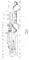
- the machine comprises a head working 1, coupled to a heavy shoe 2 itself fixed to a lifting arm 3 of the frame hitch 4.
- the working head 1 (FIGS. 4 and 5) comprises a geared motor for preferably consisting of a hydraulic motor 5 and a reducing gear 6 a rotor 7 by means of a shaft 8 mounted rotating in a casing 9.
- the reducer 6 is a gear reducer allowing the hydraulic motor 5 to be shifted inwards relative to the center of the working head 1, thus moving the latter away from the vines between which he might hit while working.
- the tools When the machine is used as a weeding machine or machine analogous ( Figure 4) for removing harmful weeds and plants and / or loosen the soil surface, the tools consist of weights with a somewhat sharp leading edge. In a very advantageous, these weeding tools 10A are of a particular type described in a other Applicant's Patent Application.
- the tools consist of blades or knives 10B ( Figure 5).
- the rotor 7, the tools 10A or 10B and the removable fixing system for these the latter are shaped and arranged to allow mounting on said rotor, with a freedom of pivoting of limited amplitude, of at least two tools 10A or 10B.
- the tools 10A or 10B are mounted in conditions such as when these are installed on the rotor, their axes of pivoting B-B converge downwards towards the axis A-A of the latter, in forming an angle ⁇ with said axis of rotation A-A, for example an angle of the order 9 °.
- the removable attachment system for tools 10A or 10B includes, for each of these, a hinge pin 11 around which is mounted, with a pivoting ability, the hinge ring 10a of the tool.
- One end of this articulation axis is housed in a borehole in the vicinity of the periphery of the rotor 7, while its opposite end is engaged in a opening provided by a mounting flange 12.
- a pressure washer 15 can be arranged around the lower end of the hinge pin 11, between a circular shoulder 11a of the latter, and the fixing flange 12, so as to allow the tool to pivot.
- the holes in the rotor 7 for mounting the tools interchangeable 10A or 10B have an axis B-B inclined to the axis of rotation A-A of said rotor, so that the axes of articulation 11 and the axes of the rings of mounting 10a are also inclined along the axis B-B.
- the flange 12 is fixed axially to the base of the rotor 7 by means of a single screw 13 passing through a central orifice of said flange and screwing into a thread formed in the lower portion of the tree 8.
- the working head of the soil cultivating machine according to the invention can be equipped with at least two tools 10A or 10B, but its rotor 7 can be shaped to receive three or more tools, angularly and regularly spaced.
- This arrangement makes it possible to reduce the violence of possible shocks and avoid premature knives being put out of use.
- the rotor 7 has a cylindrical lower part 7a of more diameter reduced than that of its upper part 7b under which the tools 10A are fixed or 10B.
- This cylindrical lower part 7a serves as a stop limiting the movement retracting tools backwards when they encounter an obstacle hard.
- a rotating guide 14 is arranged above the tools 10A or 10B, preferably coaxially with the axis of rotation A-A of the latter.
- This guide is, for example, mounted around the lower cylindrical portion 9a of the casing 9, via of a bearing 37, so that it can rotate around the axis of rotation A-A of the rotor 7.
- This rotating guide presents, seen in the direction of the axis A-A, the shape general of a notched disc comprising, alternately, at its periphery, notches 16 and projecting parts 17.
- the working head 1 thus produced is arranged so that the length of the maximum radius of action R1 of rotary tools 10A or 10B is less than or equal to the length of the radius R2 of a circle tangent to the bottom of the notches 16 of said guide.
- said guide is dimensioned so that the length of the maximum radius of action R1 of the tools rotary 10A or 10B, either less than or equal to the length of the radius R2 of a circle tangent to the bottom of the notches 16 of said guide ( Figure 2).
- the indented guide 14 is mounted for free rotation.
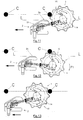
- FIGS 11 to 13 illustrate the mode of action of the indented rotary guide 14 according to the invention.
- the guide 14 engages with said vine, via one of its notches 16 ( Figure 11).
- the machine continuing to progress parallel to the alignment of vines, the guide 14 rolls around the vine with which it is engaged, moving away from its normal trajectory (figure 12). It thus travels around the vine C corresponding to approximately the semi-circumference of the latter, path during which the stock remains constantly in the bottom of the notch 16, so that the tools weeding machine 10A or mower blades 10B continuously work very near said vine, but without being able to touch and injure it.
- the meshing guide 14 present, in its central part 14a approximately delimited by the bottom of the notches 16, the general shape of a bell.
- the base of this bell is included in a foreground P-P delimiting a space closed E in which the rotor 7, the base of which is located above, is entirely housed of said plan P-P, so that its lower part does not drag on the ground when the machine is working.
- the blades or 10B knives are also housed in the space E delimited by the base of the bell 14a and are above the plane P-P, so that they do not scrape the ground.
- the base of the bell is placed above and at a distance from a second plane P'-P ' below which are the weeding tools 10A.
- the peripheral teeth or projecting parts 17 of the meshing guide 14 are raised relative to the base of its central part, so that said guide has the shape of a bell with a crenellated border.
- the raised projections have a curved external surface 17a in the vertical direction, this arrangement favoring the sliding of the bell guide on the ground.
- the meshing guide thus shaped can easily climb overhangs, while that its ability to slide easily, allows it to return to its position normal with weaker springs, as explained below.
- the guide 14 has a peripheral rim 14c oriented to the top.
- the bell-shaped guide 14 can advantageously be made of a material with an elastic deformation capacity, such as, for example, in abrasion-resistant polyurethane.
- the meshing guide is preferably mounted with free rotation.
- rotation of the weeding tools 10A to a speed of the order of 200 to 1500 revolutions / minute causes a stir of the earth which plays the role of a friction clutch turning the bell, as if it was driving, the tools and the bell then turning in the same direction.
- the working head 1 is coupled to a heavy shoe 2 shaped to be able to slide easily on the ground S, by means of a coupling device allowing pivoting movements of said working head about at least two axes orthogonal.
- This positioning pad consists of a heavy piece of metal having, seen from above, an approximately trapezoidal shape. It has a flat sole and its front face has, in its lower part, a surface curve 2a favoring its sliding on the ground by preventing it from digging a furrow in this last.
- this skate can have a weight of the order of 50 kg.
- its external lateral face comprises at the front, a sloping part 2c with respect to its longitudinal axis and connecting to a posterior part substantially flat 2b parallel to said axis.
- the shoe In its rear part, the shoe has a wide opening 18 opening out to the rear. This opening prevents it from forming a jam between the shoe 2 and the enveloping guide 14 of the working head.
- the positioning pad 2 is connected to the working head by means of a coupling arm 19.
- the front end of this arm is fixed to the shoe 2 by means of a cardan joint type connecting device. More specifically, the arm 19 is fixed by means of a cylindrical articulation with horizontal axis 20 in a yoke 21a that has an arm support 21. This yoke is mounted with an aptitude pivoting on a vertical axis 22 rigidly secured to the shoe 2 and rising to from the central area of it.
- the arm can thus pivot around two perpendicular axes, so that the working head attached to the posterior end of this arm can tilt in the vertical direction around from the horizontal axis 20 and pivot laterally to the right or left around the axis vertical 22.
- the circular guide 14 In normal position corresponding to the working position of the machine between the stocks C, the circular guide 14 is placed, at least in part and, preferably at least half, outside an L-L line passing through the edge outer 2b of pad 2 ( Figure 11).
- skate 2 via its sloping face 2c, preposition the working head 1 and the guide 14 engages with said vine, around of which it rolls while moving (according to arrow F1 of figure 12) inwards, direction of the center of the inter-rows.
- Means hold the working head 1 in this position, and allow the lateral displacement of said head towards the inter-row and ensure its return to normal position, after passage of the vine.
- These means are, for example, constituted by a helical spring 23 disposed around the cylindrical sleeve 21b for mounting the arm support 21 and fixed, through its ends, on the one hand, in a hole 24 that has this and, on the other hand, in a hole 25 that has an organ rigidly secured to the axis 22 or the shoe 2.
- the arm support 21 and / or the shoe (or the fixing member rigidly integral with said pad) may or may have several holes located on an arc (figure 2) to allow change the location of the anchor point of at least one of the ends of the spring 23. It is thus possible to adjust the return torque or stiffness of this latest.
- a shock absorber preferably constituted by a shock absorber adjustable hydraulic 26, connects the arm support 21 or casing of the device to gimbal and the coupling arm 19.
- This shock absorber 26 makes it possible to stabilize the weeding or mowing head while working, avoiding the latter does not progress by successive rebounds, especially on stony terrain; he therefore allows better work in good safety conditions.
- the working head 1 is mounted with a tilting latitude around a axis parallel to the longitudinal axis of skate 2 or crew advancement axis: shoe 2 - work head 1.
- the rear end of the coupling arm 19 is connected to the head of work 1, by means of a cylindrical articulation 27, so that said working head can tilt around said end.
- a stop system preferably adjustable, limits the amplitude of this tilting, so as to prevent the working head from tipping over with too large an extent creating a risk of the head overturning.
- This stop system is, for example, constituted by a helical spring 28 arranged around the coupling arm 19 and fixed, on the one hand, to a sleeve 29 or other piece rigidly secured to the casing 9 of the working head and, on the other hand, to a ring 30 mounted around said arm and made integral with the latter by example by means of a pressure screw 31, or other assembly member removable allowing the angular position of said ring to be modified. This adjusts the stiffness of spring 28.
- the above arrangement allows to dampen the tipping movements of the weeding head, or mowing, during work and press the base of the bell guide against the ground, in particular when it is in the areas of contact with the vines.
- the skate moves by closely marrying the surface of the ground whatever the inequalities encountered during its progression (slopes or overhang).
- the transverse axis 34 makes it possible to follow the conformation of the ground in the direction of travel, while the axis longitudinal 32 overcomes problems of slope. In this way, the weeding or mowing head 1 coupled to said skid, behaves similarly and the enveloping guide 14 remains pressed against the ground whatever the configuration of it.
- a balancing device preferably adjustable, for example constituted by a helical spring 36 acting in traction, is fixed, by means of its opposite ends, on the one hand, at a point close to the distal end of the arm 3 and, on the other hand, to the front part of the skate; this balancing spring avoids that the skate is not planted in the ground, limiting the amplitude of its tilting forward.
- Figure 6 shows, by way of example, a tilting position of the shoe 2 around the axis 32 corresponding to the sliding of said shoe on a ground in slightly overhanging.
- Figure 7 illustrates the action of a weeding head moving on a ground on a slope; we see that thanks to the bell-shaped guide, the tools are ideally positioned in the soil S, to effectively fulfill their function.
- the shoe 2 when meeting a C or other cep vertical obstacle, the shoe 2 can be caused to slide, by means of its sloping surface 2c, on said obstacle, so that said shoe is pushed back laterally towards the center of the inter-row of vines in which the working head.
- the distal end of the arm 3 is arranged so as to allow this movement and to ensure the return of the skate to its normal position. This situation is illustrated in figures 9 and 10.
- the sleeve 35 in which the axis 34 is housed is rigidly secured to the lower end of a tilting part 38 whose upper part is fixed, by means of a joint 39, on the distal end of the arm 3.
- On the end of this part is fixed, by means of a joint 40, one of the ends of a rod 41 around which is arranged a spring 42 acting in extension.
- This spring 42 is wedged, through its opposite ends, on the one hand, against a washer 43 held by a nut 44 screwing onto the free end of the rod 41, and, on the other hand, against a stop 45 pivotally mounted, by through axes 46, in a yoke 47 rigidly secured to the bottom 3.
- FIG. 9 illustrates a position for erasing the shoe 2, in the direction of the center of the inter-rows, according to which the spring 42 of the device previously described is compressed, while in the return to position situation normal shown in Figure 10, said spring is relaxed.
- the lifting hitch frame supporting the arm 3 is mounted so that removable, on an adapter fitting 48 fixed to the vehicle chassis carrier, on the side, or at the front, or at the rear, right or left of the latter.
Abstract
Description
- le premier de ces problèmes est constitué par le fait que la tête de sarclage s'escamote à l'approche du pied de la plante et reprend sa place dans l'interpieds après dépassement de ladite plante ; si l'on considère que le système hydraulique assurant l'escamotage a des temps de réponse relativement longs, on comprend que, pour que la tête de sarclage revienne se replacer dans l'interpieds aussi près que possible du pied qu'elle vient de dépasser, il faut que la machine se déplace lentement car, dans le cas contraire, ladite tête se trouverait trop éloignée de ce pied lors de son retour en position, en laissant ainsi des zones supplémentaires de terre non travaillées.
- le second résulte du fait que la rotation à grande vitesse de leur tête de travail entraínerait des projections dangereuses de pierres.
- un axe 32 fixé rigidement sur le patin 2 et orienté parallèlement à l'axe longitudinal de celui-ci ;
- une pièce en forme de T constituée d'une douille 33 et d'un axe 34 orienté transversalement et rigidement solidaire de celle-ci ; cette douille étant montée à rotation libre autour de l'axe 32 ;
- une douille 35 fixée à l'extrémité distale du bras 3 et dans laquelle est monté l'axe 34, avec une latitude de rotation.
Claims (21)
- Machine polyvalente de culture interpieds pour plantations d'arbres ou arbustes, telles que vignes ou vergers comprenant une tête de travail (1) comportant un rotor (7) entraíné par un moteur (5-6) et agencé pour recevoir au moins deux outils interchangeables (10A ou 10B), caractérisée en ce qu'elle comprend un guide engrenant (14) disposé au-dessus des outils (10A ou 10B), ce guide engrenant (14) étant apte à tourner autour de son axe de rotation et ayant, vue dans la direction de cet axe, la forme générale d'un disque échancré présentant, alternativement, à sa périphérie, des échancrures (16) et des parties saillantes (17), la longueur du rayon d'action (R1) desdits outils rotatifs (10A ou 10B) étant inférieure ou égale à celle du rayon (R2) d'un cercle tangent au fond desdites échancrures (16) du guide engrenant.
- Machine polyvalente de culture interpieds selon la revendication 1, caractérisée en ce que le guide engrenant (14) présente dans sa partie centrale, la forme générale d'une cloche (14a).
- Machine polyvalente de culture interpieds suivant l'une des revendications 1 ou 2, caractérisée en ce que le guide engrenant (14) est monté coaxialement à l'axe de rotation (A-A) du rotor (7).
- Machine polyvalente de culture interpieds selon l'une des revendications 2 ou 3, caractérisée en ce que le rotor (7) sur lequel sont fixés les outils de sarclage (10A ou 10B) est entièrement logé dans l'espace clos délimité par la base de la cloche (14a).
- Machine polyvalente de culture interpieds selon l'une quelconque des revendications 2 à 4, caractérisée en ce que les outils (10B) sont entièrement contenus dans l'espace délimité par la base de la cloche (14a).
- Machine polyvalente de culture interpieds suivant l'une quelconque des revendications 2 à 4, caractérisée en ce que la base de la cloche (14a) est comprise dans un premier plan (P-P) se trouvant au-dessus et à distance d'un deuxième plan (P'-P') au-dessous duquel est disposée la partie travaillante des outils (10A).
- Machine polyvalente de culture interpieds, selon l'une quelconque des revendications 2 à 6, caractérisée en ce que les parties saillantes périphériques (17) du guide engrenant (14-14a) sont relevées par rapport à la base de sa partie centrale en forme de cloche (14a).
- Machine polyvalente de culture interpieds, suivant l'une quelconque des revendications 1 à 7, caractérisée en ce que le guide engrenant 14-14a est monté à rotation libre.
- Machine polyvalente de culture interpieds suivant l'une quelconque des revendications 2 à 8, caractérisée en ce que le guide engrenant (14-14a) est réalisé dans un matériau doté d'une capacité de déformation élastique.
- Machine polyvalente de culture interpieds selon l'une quelconque des revendications 1 à 9, caractérisée en ce que les parties saillantes périphériques (17) du guide engrenant (14) présentent, la forme générale d'un triangle à sommet arrondi.
- Machine polyvalente de culture interpieds, selon l'une quelconque des revendications 1 à 10, caractérisée en ce que la tête de travail (1) est attelée à un patin pesant (2) apte à glisser sur le sol, au moyen d'un dispositif d'accouplement (19-20-21-22) autorisant des mouvements de pivotement de ladite tête de travail autour de deux axes orthogonaux ou approximativement orthogonaux.
- Machine polyvalente de culture interpieds, selon la revendication 11, caractérisée en ce qu'elle comporte des moyens (23) de maintien de la tête de travail (1) dans une position suivant laquelle son guide engrenant (14-14a) se trouve placé, au moins en partie, à l'extérieur d'une ligne (L-L) passant par le bord externe (2b) du patin (2), ces moyens permettant le déplacement de la tête de travail (1) en direction du centre de l'inter-rangs, lors de la rencontre d'un obstacle vertical (C) tel que pied de vigne, tronc d'arbre, piquets de palissage, et assurant le rappel en position de ladite tête de travail après passage dudit obstacle vertical.
- Machine polyvalente de culture interpieds selon l'une des revendications 11 ou 12, caractérisée en ce que le dispositif d'accouplement de la tête de travail (1) et du patin (2) comprend un bras d'accouplement (19) relié au moyen d'une articulation à axe horizontal (20) à un support de bras (21) lui-même fixé, avec une aptitude de pivotement, sur un axe vertical (22) rigidement solidaire du patin (2), un ressort (23) fixé, par l'intermédiaire de ses extrémités opposées, au support de bras (21) et au patin (2) ou à un organe solidaire de celui-ci, tendant à maintenir ou à rappeler ladite tête de travail (1) dans la position suivant laquelle son guide engrenant (14-14a) se trouve placé, au moins en partie, à l'extérieur d'une ligne (L-L) passant par le bord externe (2b) du patin (2).
- Machine polyvalente de culture interpieds suivant l'une quelconque des revendications 11 à 13, caractérisée en ce qu'un amortisseur (26) relie le support de bras d'accouplement (21) et le bras d'accouplement (19).
- Machine polyvalente de culture interpieds selon l'une quelconque des revendications 11 à 14, caractérisée en ce que la tête de travail (1) est montée avec une aptitude de basculement autour de l'axe de l'extrémité du bras d'accouplement (19) sur laquelle elle est installée.
- Machine polyvalente de culture interpieds suivant la revendication 15, caractérisée en ce que la tête de travail (1) est reliée à l'extrémité postérieure du bras d'accouplement par l'intermédiaire d'une articulation cylindrique (27).
- Machine polyvalente de culture interpieds, selon l'une des revendications 15 ou 16, caractérisée en ce qu'elle comporte un système de butée (28, 29, 30, 31) de préférence réglable, limitant l'amplitude du basculement de la tête de travail (1).
- Machine polyvalente de culture interpieds, suivant la revendication 17, caractérisée en ce que ledit système de butée comprend un ressort hélicoïdal (28) disposé autour du bras d'accouplement (19) et fixé, d'une part, à une pièce (29) rigidement solidaire du carter (9) de la tête de travail (1) et, d'autre part, à une bague (30) montée autour dudit bras et rendue solidaire de ce dernier au moyen d'une vis de pression (31).
- Machine polyvalente de culture interpieds suivant l'une quelconque des revendications 11 à 18, caractérisée en ce que le patin tracteur (2) est relié à l'extrémité distale du bras (3) du bâti d'attelage relevable (4), au moyen d'un dispositif d'accouplement (32, 33, 34, 35) autorisant des mouvements de pivotement dudit patin autour de deux axes orthogonaux horizontaux ou approximativement horizontaux.
- Machine polyvalente de culture interpieds, selon la revendication 19, caractérisée en ce qu'un dispositif d'équilibrage (36), de préférence réglable, est fixé, par l'intermédiaire de ses extrémités opposées, d'une part, à un point proche de l'extrémité distale du bras (3) du bâti d'attelage relevable (4) et, d'autre part, à la partie avant du patin (2).
- Machine polyvalente de culture interpieds, selon l'une quelconque des revendications 11 à 20, caractérisée en ce qu'elle comporte des moyens (40-41-42-43-44-45-46-47) permettant l'effacement latéral du patin (2) lors de la rencontre d'un obstacle dur (C) et assurant son retour en positon normale après passage dudit obstacle.
Priority Applications (11)
| Application Number | Priority Date | Filing Date | Title |
|---|---|---|---|
| EP00430008A EP1125487B1 (fr) | 2000-02-18 | 2000-02-18 | Machine polyvalente de culture interpieds pour plantations d'arbres ou arbustes telles que vignes ou vergers |
| AT00430008T ATE274292T1 (de) | 2000-02-18 | 2000-02-18 | Mehrzweckmaschine zum zwischenkultivieren für baum- oder strauchpflanzungen bzw. wein- oder obstgärten |
| ES00430008T ES2226751T3 (es) | 2000-02-18 | 2000-02-18 | Maquina polivalente de cultivo entre-pies para plantaciones de arboleso arbustos tales como viñas y vergeles. |
| DE60013240T DE60013240T2 (de) | 2000-02-18 | 2000-02-18 | Mehrzweckmaschine zum Zwischenkultivieren für Baum- oder Strauchpflanzungen bzw. Wein- oder Obstgärten |
| ARP010100568A AR028211A1 (es) | 2000-02-18 | 2001-02-08 | Maquina polivalente para el cultivo entre los tallos, para plantaciones de arboles o de arbustos tales como vinedos o huertos |
| PCT/FR2001/000434 WO2001062067A1 (fr) | 2000-02-18 | 2001-02-14 | Machine polyvalente de culture interpieds pour plantations d'arbres ou arbustes telles que vignes ou vergers |
| AU2001235676A AU2001235676B2 (en) | 2000-02-18 | 2001-02-14 | Multipurpose machine for close-row production for tree or shrub plantations such as vineyards or orchards |
| AU3567601A AU3567601A (en) | 2000-02-18 | 2001-02-14 | Multipurpose machine for close-row production for tree or shrub plantations suchas vineyards or orchards |
| US10/203,989 US6840026B2 (en) | 2000-02-18 | 2001-02-14 | Multipurpose machine for close-row production for tree or shrub plantations such as vineyards or orchards |
| EP01907794A EP1255431A1 (fr) | 2000-02-18 | 2001-02-14 | Machine polyvalente de culture interpieds pour plantations d'arbres ou arbustes telles que vignes ou vergers |
| BR0108472-0A BR0108472A (pt) | 2000-02-18 | 2001-02-14 | Máquina polivalente de cultura interpés para plantações de árvores ou arbustos tais como vinhas ou pomares |
Applications Claiming Priority (1)
| Application Number | Priority Date | Filing Date | Title |
|---|---|---|---|
| EP00430008A EP1125487B1 (fr) | 2000-02-18 | 2000-02-18 | Machine polyvalente de culture interpieds pour plantations d'arbres ou arbustes telles que vignes ou vergers |
Publications (2)
| Publication Number | Publication Date |
|---|---|
| EP1125487A1 true EP1125487A1 (fr) | 2001-08-22 |
| EP1125487B1 EP1125487B1 (fr) | 2004-08-25 |
Family
ID=8174069
Family Applications (2)
| Application Number | Title | Priority Date | Filing Date |
|---|---|---|---|
| EP00430008A Expired - Lifetime EP1125487B1 (fr) | 2000-02-18 | 2000-02-18 | Machine polyvalente de culture interpieds pour plantations d'arbres ou arbustes telles que vignes ou vergers |
| EP01907794A Withdrawn EP1255431A1 (fr) | 2000-02-18 | 2001-02-14 | Machine polyvalente de culture interpieds pour plantations d'arbres ou arbustes telles que vignes ou vergers |
Family Applications After (1)
| Application Number | Title | Priority Date | Filing Date |
|---|---|---|---|
| EP01907794A Withdrawn EP1255431A1 (fr) | 2000-02-18 | 2001-02-14 | Machine polyvalente de culture interpieds pour plantations d'arbres ou arbustes telles que vignes ou vergers |
Country Status (9)
| Country | Link |
|---|---|
| US (1) | US6840026B2 (fr) |
| EP (2) | EP1125487B1 (fr) |
| AR (1) | AR028211A1 (fr) |
| AT (1) | ATE274292T1 (fr) |
| AU (2) | AU2001235676B2 (fr) |
| BR (1) | BR0108472A (fr) |
| DE (1) | DE60013240T2 (fr) |
| ES (1) | ES2226751T3 (fr) |
| WO (1) | WO2001062067A1 (fr) |
Cited By (3)
| Publication number | Priority date | Publication date | Assignee | Title |
|---|---|---|---|---|
| WO2013034820A1 (fr) | 2011-09-05 | 2013-03-14 | Cgc Agri | Procédé et machine de travail du sol entre des plantations |
| FR3044203A1 (fr) * | 2015-11-26 | 2017-06-02 | Ab Hydro-Concept | Dispositif porte outils destine a etre utilise par un engin tracteur |
| FR3126844A1 (fr) * | 2021-09-16 | 2023-03-17 | Solhead | Dispositif de contrôle de l’enherbement sous un rang de plantes |
Families Citing this family (12)
| Publication number | Priority date | Publication date | Assignee | Title |
|---|---|---|---|---|
| DE10351537A1 (de) * | 2003-11-03 | 2005-06-09 | Joachim Wiedmann | Verfahren zum Betreiben einer einem Fahrzeug zugeordneten Mäheinrichtung |
| US7175380B2 (en) * | 2003-12-10 | 2007-02-13 | Alamo Group, Inc. | Slewing ring boom mower |
| US20060288681A1 (en) * | 2005-06-10 | 2006-12-28 | Daniel Kuzub | Vertical pivoting arm apparatus for offset towing |
| FR2902280B1 (fr) * | 2006-06-19 | 2010-03-26 | Pellenc Sa | Porte-outils multifonctionnel se fixant en partie arriere d'un engin porteur |
| US20120227562A1 (en) * | 2009-05-04 | 2012-09-13 | Gingras Claude A | Versatile saw |
| US8713904B1 (en) | 2013-03-15 | 2014-05-06 | Harlan Clifford Goudy | Mower for cutting around or near obstacles |
| FI20145417A (fi) * | 2014-05-07 | 2015-11-08 | Lauri Aatos Vallius | Leikkuupää ja työkone |
| US10645854B2 (en) | 2018-06-01 | 2020-05-12 | Andrew J. Flocchini | Cutting head for vineyard and orchard tiller/cultivator |
| EP4079137A1 (fr) * | 2021-04-23 | 2022-10-26 | Igor Gottardi | Machine agricole |
| FR3124919B1 (fr) * | 2021-07-07 | 2023-11-17 | Bg Sarl | Dispositif de désherbage mécanique |
| CN114271047B (zh) * | 2021-12-06 | 2023-07-28 | 安徽沐茂生态农业科技有限责任公司 | 一种作坊式山芋种植用翻秧装置 |
| WO2023219495A1 (fr) * | 2022-05-10 | 2023-11-16 | Van Tuijl Innovations B.V. | Bineuse |
Citations (9)
| Publication number | Priority date | Publication date | Assignee | Title |
|---|---|---|---|---|
| US2206283A (en) * | 1940-07-02 | Cultivator for vineyards | ||
| FR86321E (fr) * | 1962-07-03 | 1966-01-24 | Décavaillonneuse rotative | |
| FR1469298A (fr) * | 1966-01-26 | 1967-02-10 | Machine décavaillonneuse et broyeuse de sarments | |
| FR1577988A (fr) | 1968-04-19 | 1969-08-14 | ||
| FR2109237A5 (fr) * | 1970-10-08 | 1972-05-26 | Ballu Gabriel | |
| US4332299A (en) | 1980-06-19 | 1982-06-01 | Eldon K. Chinn | Cultivator device for a vehicle |
| DE3507475A1 (de) * | 1985-03-02 | 1986-09-04 | Maschinenfabrik Bermatingen GmbH & Co, 7775 Bermatingen | Bodenbearbeitungsmaschine |
| FR2683117A1 (fr) | 1991-10-31 | 1993-05-07 | Terral Christian | Dispositif associe a une decavaillonneuse. |
| FR2770740A1 (fr) * | 1997-11-07 | 1999-05-14 | Smvh Dm Hydro Sarl | Dechausseuse agricole rotative |
Family Cites Families (10)
| Publication number | Priority date | Publication date | Assignee | Title |
|---|---|---|---|---|
| US2838901A (en) * | 1957-05-10 | 1958-06-17 | Herbert W Davis | Tractor mounted rotating disk cutting assembly with overload release means |
| US3059704A (en) * | 1960-10-21 | 1962-10-23 | Kasatkin Anatol | Rotary cultivator |
| US3526083A (en) * | 1967-12-19 | 1970-09-01 | Robert O Barry | Post mower |
| US3715872A (en) * | 1971-07-19 | 1973-02-13 | P Thompson | Mowing apparatus |
| NL8202143A (nl) * | 1982-05-26 | 1983-12-16 | Lely Nv C Van Der | Grondbewerkingsmachine. |
| US4802327A (en) * | 1986-09-04 | 1989-02-07 | Roberts Charles A | Mower attachment |
| IL103671A (en) * | 1992-11-06 | 1996-06-18 | Manor Gedalyahu | Forest-clearing equipment mounted on tractor |
| AUPM664294A0 (en) * | 1994-07-05 | 1994-07-28 | Fix, Wolfram Michael | Cultivator |
| US5430999A (en) * | 1994-09-01 | 1995-07-11 | Grant; Spencer A. | Tree trimming and pruning machine |
| US6311746B1 (en) * | 2000-08-07 | 2001-11-06 | Alamo Group Inc. | Circular saw head |
-
2000
- 2000-02-18 EP EP00430008A patent/EP1125487B1/fr not_active Expired - Lifetime
- 2000-02-18 ES ES00430008T patent/ES2226751T3/es not_active Expired - Lifetime
- 2000-02-18 AT AT00430008T patent/ATE274292T1/de active
- 2000-02-18 DE DE60013240T patent/DE60013240T2/de not_active Expired - Lifetime
-
2001
- 2001-02-08 AR ARP010100568A patent/AR028211A1/es unknown
- 2001-02-14 AU AU2001235676A patent/AU2001235676B2/en not_active Ceased
- 2001-02-14 EP EP01907794A patent/EP1255431A1/fr not_active Withdrawn
- 2001-02-14 AU AU3567601A patent/AU3567601A/xx active Pending
- 2001-02-14 BR BR0108472-0A patent/BR0108472A/pt not_active Application Discontinuation
- 2001-02-14 WO PCT/FR2001/000434 patent/WO2001062067A1/fr not_active Application Discontinuation
- 2001-02-14 US US10/203,989 patent/US6840026B2/en not_active Expired - Fee Related
Patent Citations (9)
| Publication number | Priority date | Publication date | Assignee | Title |
|---|---|---|---|---|
| US2206283A (en) * | 1940-07-02 | Cultivator for vineyards | ||
| FR86321E (fr) * | 1962-07-03 | 1966-01-24 | Décavaillonneuse rotative | |
| FR1469298A (fr) * | 1966-01-26 | 1967-02-10 | Machine décavaillonneuse et broyeuse de sarments | |
| FR1577988A (fr) | 1968-04-19 | 1969-08-14 | ||
| FR2109237A5 (fr) * | 1970-10-08 | 1972-05-26 | Ballu Gabriel | |
| US4332299A (en) | 1980-06-19 | 1982-06-01 | Eldon K. Chinn | Cultivator device for a vehicle |
| DE3507475A1 (de) * | 1985-03-02 | 1986-09-04 | Maschinenfabrik Bermatingen GmbH & Co, 7775 Bermatingen | Bodenbearbeitungsmaschine |
| FR2683117A1 (fr) | 1991-10-31 | 1993-05-07 | Terral Christian | Dispositif associe a une decavaillonneuse. |
| FR2770740A1 (fr) * | 1997-11-07 | 1999-05-14 | Smvh Dm Hydro Sarl | Dechausseuse agricole rotative |
Cited By (3)
| Publication number | Priority date | Publication date | Assignee | Title |
|---|---|---|---|---|
| WO2013034820A1 (fr) | 2011-09-05 | 2013-03-14 | Cgc Agri | Procédé et machine de travail du sol entre des plantations |
| FR3044203A1 (fr) * | 2015-11-26 | 2017-06-02 | Ab Hydro-Concept | Dispositif porte outils destine a etre utilise par un engin tracteur |
| FR3126844A1 (fr) * | 2021-09-16 | 2023-03-17 | Solhead | Dispositif de contrôle de l’enherbement sous un rang de plantes |
Also Published As
| Publication number | Publication date |
|---|---|
| US20030089508A1 (en) | 2003-05-15 |
| BR0108472A (pt) | 2003-04-22 |
| ATE274292T1 (de) | 2004-09-15 |
| DE60013240D1 (de) | 2004-09-30 |
| AU2001235676B2 (en) | 2004-12-09 |
| DE60013240T2 (de) | 2005-09-01 |
| EP1255431A1 (fr) | 2002-11-13 |
| AR028211A1 (es) | 2003-04-30 |
| ES2226751T3 (es) | 2005-04-01 |
| AU3567601A (en) | 2001-09-03 |
| WO2001062067A1 (fr) | 2001-08-30 |
| EP1125487B1 (fr) | 2004-08-25 |
| US6840026B2 (en) | 2005-01-11 |
Similar Documents
| Publication | Publication Date | Title |
|---|---|---|
| EP1125487B1 (fr) | Machine polyvalente de culture interpieds pour plantations d'arbres ou arbustes telles que vignes ou vergers | |
| EP0211785B1 (fr) | Faucheuse | |
| CA2226656C (fr) | Machine agricole de coupe perfectionnee | |
| EP0337909B1 (fr) | Faucheuse à entraînement direct | |
| EP0099314B1 (fr) | Dispositif empêchant l'accumulation de terre au carter d'une faucheuse à disques | |
| EP0147344A2 (fr) | Machine de coupe utilisable en agriculture, viticulture et arboriculture | |
| WO2005077138A1 (fr) | Machine de travail du sol, du type dechaumeuse | |
| EP0345183B1 (fr) | Machine de fenaison comportant un rotor pour andaîner | |
| EP1125486B1 (fr) | Outil pour machine à cultiver le sol et machine utilisant de tels outils | |
| EP2923539A1 (fr) | Semoir avec un rouleau intégré pour détruire un couvert végétal | |
| EP1169901B1 (fr) | Machine de travail du sol | |
| EP2232970B1 (fr) | Disque de labour et engin de labour comportant au moins un train équipé d'au moins un tel disque | |
| FR2938400A1 (fr) | Equipement pour travaux agricoles au pied des vignes | |
| EP0217720B1 (fr) | Machine agricole de travail du sol à rotor entraîné autour d'un axe oblique | |
| EP0680688B1 (fr) | Machine de fenaison, notamment un andaineur de fourrage | |
| EP0168328B1 (fr) | Outil agricole tel qu'une écrouteuse | |
| EP2268122B1 (fr) | Machine agricole destinee a la destruction de la couverture vegetale du sol par elimination mecanique | |
| FR3069748B1 (fr) | Outil de travail du sol entraine et dispositif de travail de la terre equipe d'au moins un tel outil de travail du sol | |
| EP0346255B1 (fr) | Machine agricole de travail du sol munie de socs et d'un rotor | |
| FR2688376A1 (fr) | Rouleau de travail du sol et machine le comportant. | |
| FR2943490A1 (fr) | Disque de labour et engin de labour comportant au moins un train equipe d'un tel disque | |
| FR2990100A1 (fr) | Machine agricole du travail du sol pour l'entretien des vergers, des vignes ou similaires | |
| FR2688526A1 (fr) | Dispositif de damage et machine de travail du sol le comportant. | |
| FR2770740A1 (fr) | Dechausseuse agricole rotative | |
| FR2646315A1 (fr) | Machine agricole comportant au moins un rotor muni d'outils et s'appuyant sur le sol durant le travail |
Legal Events
| Date | Code | Title | Description |
|---|---|---|---|
| PUAI | Public reference made under article 153(3) epc to a published international application that has entered the european phase |
Free format text: ORIGINAL CODE: 0009012 |
|
| AK | Designated contracting states |
Kind code of ref document: A1 Designated state(s): AT BE CH CY DE DK ES FI FR GB GR IE IT LI LU MC NL PT SE |
|
| AX | Request for extension of the european patent |
Free format text: AL;LT;LV;MK;RO;SI |
|
| 17P | Request for examination filed |
Effective date: 20011022 |
|
| 17Q | First examination report despatched |
Effective date: 20020226 |
|
| AKX | Designation fees paid |
Free format text: AT BE CH CY DE DK ES FI FR GB GR IE IT LI LU MC NL PT SE |
|
| GRAP | Despatch of communication of intention to grant a patent |
Free format text: ORIGINAL CODE: EPIDOSNIGR1 |
|
| GRAS | Grant fee paid |
Free format text: ORIGINAL CODE: EPIDOSNIGR3 |
|
| GRAA | (expected) grant |
Free format text: ORIGINAL CODE: 0009210 |
|
| AK | Designated contracting states |
Kind code of ref document: B1 Designated state(s): AT BE CH CY DE DK ES FI FR GB GR IE IT LI LU MC NL PT SE |
|
| PG25 | Lapsed in a contracting state [announced via postgrant information from national office to epo] |
Ref country code: IE Free format text: LAPSE BECAUSE OF FAILURE TO SUBMIT A TRANSLATION OF THE DESCRIPTION OR TO PAY THE FEE WITHIN THE PRESCRIBED TIME-LIMIT Effective date: 20040825 Ref country code: NL Free format text: LAPSE BECAUSE OF FAILURE TO SUBMIT A TRANSLATION OF THE DESCRIPTION OR TO PAY THE FEE WITHIN THE PRESCRIBED TIME-LIMIT Effective date: 20040825 Ref country code: GB Free format text: LAPSE BECAUSE OF FAILURE TO SUBMIT A TRANSLATION OF THE DESCRIPTION OR TO PAY THE FEE WITHIN THE PRESCRIBED TIME-LIMIT Effective date: 20040825 Ref country code: FI Free format text: LAPSE BECAUSE OF FAILURE TO SUBMIT A TRANSLATION OF THE DESCRIPTION OR TO PAY THE FEE WITHIN THE PRESCRIBED TIME-LIMIT Effective date: 20040825 |
|
| REG | Reference to a national code |
Ref country code: GB Ref legal event code: FG4D Free format text: NOT ENGLISH |
|
| REG | Reference to a national code |
Ref country code: CH Ref legal event code: EP |
|
| REG | Reference to a national code |
Ref country code: IE Ref legal event code: FG4D Free format text: FRENCH |
|
| REF | Corresponds to: |
Ref document number: 60013240 Country of ref document: DE Date of ref document: 20040930 Kind code of ref document: P |
|
| PG25 | Lapsed in a contracting state [announced via postgrant information from national office to epo] |
Ref country code: SE Free format text: LAPSE BECAUSE OF FAILURE TO SUBMIT A TRANSLATION OF THE DESCRIPTION OR TO PAY THE FEE WITHIN THE PRESCRIBED TIME-LIMIT Effective date: 20041125 Ref country code: DK Free format text: LAPSE BECAUSE OF FAILURE TO SUBMIT A TRANSLATION OF THE DESCRIPTION OR TO PAY THE FEE WITHIN THE PRESCRIBED TIME-LIMIT Effective date: 20041125 Ref country code: GR Free format text: LAPSE BECAUSE OF FAILURE TO SUBMIT A TRANSLATION OF THE DESCRIPTION OR TO PAY THE FEE WITHIN THE PRESCRIBED TIME-LIMIT Effective date: 20041125 |
|
| PG25 | Lapsed in a contracting state [announced via postgrant information from national office to epo] |
Ref country code: LU Free format text: LAPSE BECAUSE OF NON-PAYMENT OF DUE FEES Effective date: 20050218 Ref country code: CY Free format text: LAPSE BECAUSE OF FAILURE TO SUBMIT A TRANSLATION OF THE DESCRIPTION OR TO PAY THE FEE WITHIN THE PRESCRIBED TIME-LIMIT Effective date: 20050218 |
|
| PG25 | Lapsed in a contracting state [announced via postgrant information from national office to epo] |
Ref country code: LI Free format text: LAPSE BECAUSE OF NON-PAYMENT OF DUE FEES Effective date: 20050228 Ref country code: CH Free format text: LAPSE BECAUSE OF NON-PAYMENT OF DUE FEES Effective date: 20050228 Ref country code: BE Free format text: LAPSE BECAUSE OF NON-PAYMENT OF DUE FEES Effective date: 20050228 Ref country code: MC Free format text: LAPSE BECAUSE OF NON-PAYMENT OF DUE FEES Effective date: 20050228 |
|
| NLV1 | Nl: lapsed or annulled due to failure to fulfill the requirements of art. 29p and 29m of the patents act | ||
| GBV | Gb: ep patent (uk) treated as always having been void in accordance with gb section 77(7)/1977 [no translation filed] |
Effective date: 20040825 |
|
| REG | Reference to a national code |
Ref country code: IE Ref legal event code: FD4D |
|
| REG | Reference to a national code |
Ref country code: ES Ref legal event code: FG2A Ref document number: 2226751 Country of ref document: ES Kind code of ref document: T3 |
|
| PLBE | No opposition filed within time limit |
Free format text: ORIGINAL CODE: 0009261 |
|
| STAA | Information on the status of an ep patent application or granted ep patent |
Free format text: STATUS: NO OPPOSITION FILED WITHIN TIME LIMIT |
|
| 26N | No opposition filed |
Effective date: 20050526 |
|
| BERE | Be: lapsed |
Owner name: S.A. *PELLENC Effective date: 20050228 |
|
| REG | Reference to a national code |
Ref country code: CH Ref legal event code: PL |
|
| BERE | Be: lapsed |
Owner name: S.A. *PELLENC Effective date: 20050228 |
|
| PG25 | Lapsed in a contracting state [announced via postgrant information from national office to epo] |
Ref country code: PT Free format text: LAPSE BECAUSE OF NON-PAYMENT OF DUE FEES Effective date: 20050125 |
|
| PGFP | Annual fee paid to national office [announced via postgrant information from national office to epo] |
Ref country code: IT Payment date: 20120223 Year of fee payment: 13 |
|
| PGFP | Annual fee paid to national office [announced via postgrant information from national office to epo] |
Ref country code: DE Payment date: 20120426 Year of fee payment: 13 |
|
| PGFP | Annual fee paid to national office [announced via postgrant information from national office to epo] |
Ref country code: AT Payment date: 20120221 Year of fee payment: 13 |
|
| PGFP | Annual fee paid to national office [announced via postgrant information from national office to epo] |
Ref country code: FR Payment date: 20130329 Year of fee payment: 14 |
|
| PGFP | Annual fee paid to national office [announced via postgrant information from national office to epo] |
Ref country code: ES Payment date: 20120216 Year of fee payment: 13 |
|
| REG | Reference to a national code |
Ref country code: AT Ref legal event code: MM01 Ref document number: 274292 Country of ref document: AT Kind code of ref document: T Effective date: 20130228 |
|
| PG25 | Lapsed in a contracting state [announced via postgrant information from national office to epo] |
Ref country code: AT Free format text: LAPSE BECAUSE OF NON-PAYMENT OF DUE FEES Effective date: 20130228 |
|
| REG | Reference to a national code |
Ref country code: DE Ref legal event code: R119 Ref document number: 60013240 Country of ref document: DE Effective date: 20130903 |
|
| PG25 | Lapsed in a contracting state [announced via postgrant information from national office to epo] |
Ref country code: IT Free format text: LAPSE BECAUSE OF NON-PAYMENT OF DUE FEES Effective date: 20130218 |
|
| PG25 | Lapsed in a contracting state [announced via postgrant information from national office to epo] |
Ref country code: DE Free format text: LAPSE BECAUSE OF NON-PAYMENT OF DUE FEES Effective date: 20130903 |
|
| REG | Reference to a national code |
Ref country code: ES Ref legal event code: FD2A Effective date: 20140409 |
|
| PG25 | Lapsed in a contracting state [announced via postgrant information from national office to epo] |
Ref country code: ES Free format text: LAPSE BECAUSE OF NON-PAYMENT OF DUE FEES Effective date: 20130219 |
|
| REG | Reference to a national code |
Ref country code: FR Ref legal event code: ST Effective date: 20141031 |
|
| PG25 | Lapsed in a contracting state [announced via postgrant information from national office to epo] |
Ref country code: FR Free format text: LAPSE BECAUSE OF NON-PAYMENT OF DUE FEES Effective date: 20140228 |