EP1124599B1 - Dispositif de mesure du flux d'acces lors de dialyse - Google Patents
Dispositif de mesure du flux d'acces lors de dialyse Download PDFInfo
- Publication number
- EP1124599B1 EP1124599B1 EP99970926.4A EP99970926A EP1124599B1 EP 1124599 B1 EP1124599 B1 EP 1124599B1 EP 99970926 A EP99970926 A EP 99970926A EP 1124599 B1 EP1124599 B1 EP 1124599B1
- Authority
- EP
- European Patent Office
- Prior art keywords
- blood
- substance
- concentration
- dialyzer
- urea
- Prior art date
- Legal status (The legal status is an assumption and is not a legal conclusion. Google has not performed a legal analysis and makes no representation as to the accuracy of the status listed.)
- Expired - Lifetime
Links
Images


Classifications
-
- G—PHYSICS
- G01—MEASURING; TESTING
- G01F—MEASURING VOLUME, VOLUME FLOW, MASS FLOW OR LIQUID LEVEL; METERING BY VOLUME
- G01F9/00—Measuring volume flow relative to another variable, e.g. of liquid fuel for an engine
-
- A—HUMAN NECESSITIES
- A61—MEDICAL OR VETERINARY SCIENCE; HYGIENE
- A61M—DEVICES FOR INTRODUCING MEDIA INTO, OR ONTO, THE BODY; DEVICES FOR TRANSDUCING BODY MEDIA OR FOR TAKING MEDIA FROM THE BODY; DEVICES FOR PRODUCING OR ENDING SLEEP OR STUPOR
- A61M1/00—Suction or pumping devices for medical purposes; Devices for carrying-off, for treatment of, or for carrying-over, body-liquids; Drainage systems
- A61M1/14—Dialysis systems; Artificial kidneys; Blood oxygenators ; Reciprocating systems for treatment of body fluids, e.g. single needle systems for hemofiltration or pheresis
- A61M1/16—Dialysis systems; Artificial kidneys; Blood oxygenators ; Reciprocating systems for treatment of body fluids, e.g. single needle systems for hemofiltration or pheresis with membranes
- A61M1/1601—Control or regulation
- A61M1/1603—Regulation parameters
- A61M1/1605—Physical characteristics of the dialysate fluid
- A61M1/1607—Physical characteristics of the dialysate fluid before use, i.e. upstream of dialyser
-
- A—HUMAN NECESSITIES
- A61—MEDICAL OR VETERINARY SCIENCE; HYGIENE
- A61M—DEVICES FOR INTRODUCING MEDIA INTO, OR ONTO, THE BODY; DEVICES FOR TRANSDUCING BODY MEDIA OR FOR TAKING MEDIA FROM THE BODY; DEVICES FOR PRODUCING OR ENDING SLEEP OR STUPOR
- A61M1/00—Suction or pumping devices for medical purposes; Devices for carrying-off, for treatment of, or for carrying-over, body-liquids; Drainage systems
- A61M1/14—Dialysis systems; Artificial kidneys; Blood oxygenators ; Reciprocating systems for treatment of body fluids, e.g. single needle systems for hemofiltration or pheresis
- A61M1/16—Dialysis systems; Artificial kidneys; Blood oxygenators ; Reciprocating systems for treatment of body fluids, e.g. single needle systems for hemofiltration or pheresis with membranes
- A61M1/1601—Control or regulation
- A61M1/1603—Regulation parameters
- A61M1/1605—Physical characteristics of the dialysate fluid
- A61M1/1609—Physical characteristics of the dialysate fluid after use, i.e. downstream of dialyser
-
- A—HUMAN NECESSITIES
- A61—MEDICAL OR VETERINARY SCIENCE; HYGIENE
- A61M—DEVICES FOR INTRODUCING MEDIA INTO, OR ONTO, THE BODY; DEVICES FOR TRANSDUCING BODY MEDIA OR FOR TAKING MEDIA FROM THE BODY; DEVICES FOR PRODUCING OR ENDING SLEEP OR STUPOR
- A61M1/00—Suction or pumping devices for medical purposes; Devices for carrying-off, for treatment of, or for carrying-over, body-liquids; Drainage systems
- A61M1/36—Other treatment of blood in a by-pass of the natural circulatory system, e.g. temperature adaptation, irradiation ; Extra-corporeal blood circuits
- A61M1/3607—Regulation parameters
- A61M1/3609—Physical characteristics of the blood, e.g. haematocrit, urea
- A61M1/361—Physical characteristics of the blood, e.g. haematocrit, urea before treatment
-
- A—HUMAN NECESSITIES
- A61—MEDICAL OR VETERINARY SCIENCE; HYGIENE
- A61M—DEVICES FOR INTRODUCING MEDIA INTO, OR ONTO, THE BODY; DEVICES FOR TRANSDUCING BODY MEDIA OR FOR TAKING MEDIA FROM THE BODY; DEVICES FOR PRODUCING OR ENDING SLEEP OR STUPOR
- A61M1/00—Suction or pumping devices for medical purposes; Devices for carrying-off, for treatment of, or for carrying-over, body-liquids; Drainage systems
- A61M1/36—Other treatment of blood in a by-pass of the natural circulatory system, e.g. temperature adaptation, irradiation ; Extra-corporeal blood circuits
- A61M1/3621—Extra-corporeal blood circuits
- A61M1/3653—Interfaces between patient blood circulation and extra-corporal blood circuit
- A61M1/3656—Monitoring patency or flow at connection sites; Detecting disconnections
- A61M1/3658—Indicating the amount of purified blood recirculating in the fistula or shunt
-
- A—HUMAN NECESSITIES
- A61—MEDICAL OR VETERINARY SCIENCE; HYGIENE
- A61M—DEVICES FOR INTRODUCING MEDIA INTO, OR ONTO, THE BODY; DEVICES FOR TRANSDUCING BODY MEDIA OR FOR TAKING MEDIA FROM THE BODY; DEVICES FOR PRODUCING OR ENDING SLEEP OR STUPOR
- A61M1/00—Suction or pumping devices for medical purposes; Devices for carrying-off, for treatment of, or for carrying-over, body-liquids; Drainage systems
- A61M1/36—Other treatment of blood in a by-pass of the natural circulatory system, e.g. temperature adaptation, irradiation ; Extra-corporeal blood circuits
- A61M1/3621—Extra-corporeal blood circuits
- A61M1/3663—Flow rate transducers; Flow integrators
-
- A—HUMAN NECESSITIES
- A61—MEDICAL OR VETERINARY SCIENCE; HYGIENE
- A61M—DEVICES FOR INTRODUCING MEDIA INTO, OR ONTO, THE BODY; DEVICES FOR TRANSDUCING BODY MEDIA OR FOR TAKING MEDIA FROM THE BODY; DEVICES FOR PRODUCING OR ENDING SLEEP OR STUPOR
- A61M2202/00—Special media to be introduced, removed or treated
- A61M2202/04—Liquids
- A61M2202/0496—Urine
- A61M2202/0498—Urea
-
- A—HUMAN NECESSITIES
- A61—MEDICAL OR VETERINARY SCIENCE; HYGIENE
- A61M—DEVICES FOR INTRODUCING MEDIA INTO, OR ONTO, THE BODY; DEVICES FOR TRANSDUCING BODY MEDIA OR FOR TAKING MEDIA FROM THE BODY; DEVICES FOR PRODUCING OR ENDING SLEEP OR STUPOR
- A61M2205/00—General characteristics of the apparatus
- A61M2205/15—Detection of leaks
-
- A—HUMAN NECESSITIES
- A61—MEDICAL OR VETERINARY SCIENCE; HYGIENE
- A61M—DEVICES FOR INTRODUCING MEDIA INTO, OR ONTO, THE BODY; DEVICES FOR TRANSDUCING BODY MEDIA OR FOR TAKING MEDIA FROM THE BODY; DEVICES FOR PRODUCING OR ENDING SLEEP OR STUPOR
- A61M2205/00—General characteristics of the apparatus
- A61M2205/33—Controlling, regulating or measuring
- A61M2205/3317—Electromagnetic, inductive or dielectric measuring means
-
- A—HUMAN NECESSITIES
- A61—MEDICAL OR VETERINARY SCIENCE; HYGIENE
- A61M—DEVICES FOR INTRODUCING MEDIA INTO, OR ONTO, THE BODY; DEVICES FOR TRANSDUCING BODY MEDIA OR FOR TAKING MEDIA FROM THE BODY; DEVICES FOR PRODUCING OR ENDING SLEEP OR STUPOR
- A61M2205/00—General characteristics of the apparatus
- A61M2205/33—Controlling, regulating or measuring
- A61M2205/3324—PH measuring means
-
- A—HUMAN NECESSITIES
- A61—MEDICAL OR VETERINARY SCIENCE; HYGIENE
- A61M—DEVICES FOR INTRODUCING MEDIA INTO, OR ONTO, THE BODY; DEVICES FOR TRANSDUCING BODY MEDIA OR FOR TAKING MEDIA FROM THE BODY; DEVICES FOR PRODUCING OR ENDING SLEEP OR STUPOR
- A61M2205/00—General characteristics of the apparatus
- A61M2205/33—Controlling, regulating or measuring
- A61M2205/3331—Pressure; Flow
- A61M2205/3334—Measuring or controlling the flow rate
Definitions
- the present invention relates to a device which can be used in a method for measuring blood flow rate in a blood access.
- Blood is taken out from the body of a mammal to an extracorporeal blood circuit through a blood access, via needles or a catheter.
- blood is taken out in an extracorporeal blood circuit.
- treatments involve, for example, hemodialysis, hemofiltration, hemodiafiltration, plasmapheresis, blood component separation, blood oxygenation, etc.
- blood is removed from a blood vessel at an access site and returned to the same blood vessel or at another location in the body.
- an access site is commonly surgically created in the nature of a fistula.
- Blood needles are inserted in the area of the fistula. Blood is taken out from the fistula via an arterial needle and blood is returned to the fistula via a venous needle.
- a common method of generating a permanent access site having capability of providing a high blood flow and being operative during several years and even tens of years, is the provision of an arterio-venous fistula. It is produced by operatively connecting the radial artery to the cephalic vein at the level of the forearm. The venous limb of the fistula thickens during the course of several months, permitting repeated insertion of dialysis needles.
- arterio-venous fistula An alternative to the arterio-venous fistula is the arterio-venous graft, in which a connection is generated from, for example, the radial artery at the wrist to the basilic vein.
- the connection is made with a tube graft made from autogenous saphenous vein or from polytetrafluorethylene (PTFE, Teflon).
- PTFE polytetrafluorethylene
- a third method for blood access is to use a silicon, dual-lumen catheter surgically implanted into one of the large veins.
- a no-needle arterio-venous graft consisting of a T-tube linked to a standard PTFE graft.
- the T-tube is implanted in the skin.
- Vascular access is obtained either by unscrewing a plastic plug or by puncturing a septum of said T-tube with a needle.
- Other methods are also known.
- AV fistula a constant blood flow rate of 150 - 500 ml/min or even higher, and the access site must be prepared for delivering such flow rates.
- the blood flow in an AV fistula is often 800 ml/min or larger, permitting delivery of a blood flow rate in the desired range.
- the extracorporeal circuit blood pump will take up some of the already treated blood entering the fistula via the venous needle, so called access or fistula recirculation, leading to poor treatment results.
- AV fistulas The most common cause of poor flow with AV fistulas is partial obstruction of the venous limb due to fibrosis secondary to multiple venipunctures. Moreover, stenosis causes a reduction of access flow.
- a noninvazive technique that allows imaging of flow through AV grafts is color Doppler ultrasound.
- this technique requires expensive equipment.
- EP 0 773 035 describes a method for operating a blood treatment device for determining haemodynamic parameters, like a fistula flow, during extracorporeal blood treatment.
- An object of the present invention is to provide a device for measuring the access flow rate without interfering with the blood and without injecting a substance in blood.
- Another object of the invention is to provide a device for measuring access flow rate without measuring on the blood in the extracorporeal blood circuit or in the access or blood vessel.
- a further object of an embodiment of the invention is, provide a valve for reversing the blood flow.
- a possible use of the invention is to provide a method for determining when the blood flow rate is so small that risk for recirculation prevails.
- the blood flow access may be in a mammal for obtaining access to a blood vessel, such as a hemodialysis access in the nature of an arterio-venous shunt or fistula.
- a hemodialysis access in the nature of an arterio-venous shunt or fistula.
- the dialyzer clearance K is replaced by the effective dialyzer clearance Keff obtained by taking into account a cardiopulmonary recirculation and in the normal position.
- the substance is preferably selected from the group of: urea, creatinine, vitamin B12, beta-two-microglobuline and glucose, or may be an ion selected from the group of: Na + , Cl - , K + , Mg ++ , Ca ++ , HCO 3 - , acetate ion, or any combination thereof as measured by conductivity; and wherein said concentration is measured as the concentration difference between the outlet and the inlet of the dialyzer, if applicable.
- a method of measuring the concentration (Cs) of said substance in systemic venous blood comprises the steps of: stopping the blood flow in the external flow circuit for a time period sufficient to allow the cardiopulmonary circulation to equalize; starting the blood flow in the external flow circuit with a slow speed to fill the arterial line with fresh blood before the measurement; and measuring the equalized concentration of said substance in the dialysis fluid at a low dialysate flow rate or at isolated ultrafiltration. It is advantageous to make the measurement of the effective clearance at the initiation of the treatment.
- the concentration (Cs) of said substance in systemic venous blood may be estimated by: calculating a whole body mass of urea (Murea) in the body of the patient, estimating or measuring the distribution volume (V) of urea in the body of the patient; and estimating the concentration (Cs) of said substance in the blood by dividing the whole body mass of urea with the distribution volume.
- Murea whole body mass of urea
- V distribution volume
- Cs concentration of said substance in the blood by dividing the whole body mass of urea with the distribution volume.
- the mean concentration of urea in the whole body is obtained.
- the mean concentration in the whole body is slightly higher than the urea concentration in the systemic blood, except at the start of the treatment.
- this calculation should preferably be done or be extrapolated to the start of the treatment.
- a method for that purpose would be: changing the blood flow rate (Qb); monitoring the concentration of said substance in the dialysate emitted from the dialyzer; and detecting a possible fistula recirculation in the normal position by correlating a change in said concentration to said change of the blood flow rate.
- the blood flow rate is decreased and a corresponding decrease in the urea concentration is monitored, and the abscence of such a decrease being indicative of fistula recirculation.
- an access site is a site in which a fluid in a tube can be accessed and removed from and/or returned to the tube.
- the tube may be a blood vessel of a mammal, or any other tube in which a fluid is flowing.
- the access flow rate is the flow rate of the fluid in the tube or blood vessel immediately upstream of the access site or removal position.
- Fig. 1 discloses a forearm 1 of a human patient.
- the forearm 1 comprises an artery 2, in this case the radial artery, and a vein 3, in this case the cephalic vein. Openings are surgically created in the artery 2 and the vein 3 and the openings are connected to form a fistula 4, in which the arterial blood flow is cross-circuited to the vein. Due to the fistula, the blood flow through the artery and vein is increased and the vein forms an thickened area downstream of the connecting openings. When the fistula has matured after a few months, the vein is thicker and may be punctured repeatedly. Normally, the thickened vein area is called a fistula.
- An arterial needle 5 is placed in the fistula, in the enlarged vein close to the connected openings and a venous needle 6 is placed downstream of the arterial needle, normally at least five centimeters downstream thereof.
- the needles 5 and 6 are connected to a tube system 7, shown in Fig. 2 , forming an extracorporeal circuit comprising a blood pump 8, such as a dialysis circuit.
- the blood pump propels blood from the blood vessel, through the arterial needle, the extracorporeal circuit, the venous needle and back into the blood vessel.
- the extracorporeal blood circuit 7 shown in Fig. 2 further comprises an arterial clamp 9 and a venous clamp 10 for isolating the patient from the extracorporeal circuit should an error occur.
- a dialyzer 11 Downstream of pump 8 is a dialyzer 11, comprising a blood compartment 12 and a dialysis fluid compartment 13 separated by a semipermeable membrane 14. Further downstream of the dialyzer is a drip chamber 15, separating air from the blood therein.
- Blood passes from the arterial needle past the arterial clamp 9 to the blood pump 8.
- the blood pump drives the blood through the dialyzer 11 and further via the drip chamber 15 and past the venous clamp 10 back to the patient via the venous needle.
- the drip chamber may comprise an air detector, adapted to trigger an alarm should the blood emitted from the drip chamber comprise air or air bubbles.
- the blood circuit may comprise further components, such as pressure sensors etc.
- the dialysis fluid compartment 13 of the dialyzer 11 is provided with dialysis fluid via a first pump 16, which obtains dialysis fluid from a source of pure water, normally RO-water, and one or several concentrates of ions, metering pumps 17 and 18 being shown for metering such concentrates.
- the preparation of dialysis fluid is conventional and is not further described here.
- An exchange of substances between the blood and the dialysis fluid takes place in the dialyzer through the semipermeable membrane.
- urea is passed from the blood, through the semipermeable membrane and to the dialysis fluid present at the other side of the membrane.
- the exchange may take place by diffusion under the influence of a concentration gradient, so called hemodialysis, and/or by convection due to a flow of liquid from the blood to the dialysis fluid, so called ultrafiltration, which is an important feature of hemodiafiltration or hemofiltration.
- a fluid called the dialysate which is driven by a second pump 19 via a urea monitor 20 to drain.
- the urea monitor continuously measures the urea concentration in the dialysate emitted from the dialyzer, to provide a dialysate urea concentration curve during a dialysis treatment.
- Such urea concentration curve may be used for several purposes, such as obtaining a total body urea mass, as described in WO 9855166 , and to obtain a prediction of the whole body dialysis dose Kt/V as also described in said application.
- the present invention can be used in a method of non-invasively measuring the access flow in the fistula immediately before the arterial needle, using the urea monitor and the dialysis circuit as shown in Fig. 2 .
- Fig. 3 shows a simplified schematic diagram of the blood vessel circuit of a patient and a portion of the dialysis circuit according to Fig. 2 .
- the patient blood circuit comprises the heart, where the right chamber of the heart is symbolized by an upper pump 21 and the left chamber of the heart is symbolized by a lower pump 22.
- the lungs 23 are located between the upper and lower pump.
- the blood flow divides into a first branch 24 leading to the access 25, normally in the left forearm of the patient, and a second branch 26 leading to the rest of the body, such as organs, other limbs, head, etc. symbolized by a block 27.
- Blood returning from the body from the organs etc., i.e. from block 27, combines with blood returning from the access and enters the right chamber pump 21.
- the cardiac output flow rate is defined as Qco and the flow rate of the access is defined as Qa, which means that Qco - Qa enters the block 27.
- the venous blood returning from block 27 before being mixed with blood from the access, the systemic venous blood, has a urea concentration of Cs.
- the blood leaving the left chamber pump 22 has a urea concentration of Ca equal to that passing out to the access 25 as well as to the block 27.
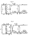
- Fig. 5 shows a valve 28 for performing the same operation.
- the arterial needle 5 is connected to an arterial inlet line 29 of the valve and the venous needle 6 is connected to a venous inlet line 30 of the valve.
- the blood pump is connected to a first outlet line 31 of the valve and the returning blood from the dialyzer 11 is connected to a second outlet line 32 of the valve.
- the valve comprises a valve housing and a pivotable valve member 33, which is pivotable from the normal position shown on the drawing to a reverse position pivoted 90° in relation to the normal position.
- the arterial needle 5 In the normal position shown in Fig. 5 , the arterial needle 5 is connected to the blood pump 8 and the venous needle 6 is connected to the outlet of the dialyzer, via the drip chamber, see Fig. 2 . In the reversed position, the arterial needle 5 is connected to the outlet of the dialyzer and the venous needle 6 is connected to the blood pump 8, as required.
- FIG. 7 An alternative design of the valve arrangement is shown in Figs. 7, 8 and 9 .
- the arterial line 29 is connected to an enlarged opening 29a and the venous outlet line 30 is connected to an enlarged opening 30a, the openings being arranged in the valve housing 28a diametrically opposite to each other.
- Two enlarged openings 31a and 32a are arranged in the valve housing 28a diametrically opposite each other and displaced 90° in relation to enlarged openings 29a and 30a.
- the pivotable valve member 33a is normally arranged as shown in Fig. 7 and forms a partition dividing the valve chamber in two semi-circular portions.
- the valve member has a width, which is smaller than the peripheral dimension of the enlarged openings.
- the valve member is pivotable 90° to a reverse position, shown in Fig. 9 , in which the blood flows through the arterial and venous needles are reversed.
- the valve member 33a During its movement from the normal to the reversed position, the valve member 33a passes through an idle position shown in Fig. 8 , in which all four enlarged openings are interconnected, because the width of the valve member is smaller than the peripheral dimension of the enlarged openings.
- this idle position harm to blood cells may be avoided. Such harm may be caused by high shear stresses which may occur if the inlet line 31 to the blood pump or the outlet line 32 from the dialyzer are completely occluded.
- the idle position another advantage is obtained, that the blood needles are not exposed to rapid change of flows, which in some instances even may result in dislocation of the needles.
- valve member When the valve member is moved from the normal position to the idle position, the flow through the needles change from the normal flow of, for example, 250 ml/min to essentially zero flow.
- the valve member may be placed in the idle position for some seconds. Then, the valve member is moved to the reversed position, and the flows through the needles is changed from essentially zero flow to -250 ml/min. In this way, a more gentle switch between normal and reversed flows may be obtained.
- the positions of the openings and the valve member may be different so that the pivotal movement may be less than or more than 90°.
- the openings need not be arranged diametrically in order to achieve the desired operation.
- the dimensions of the enlarged openings in relation to the tubes and lines are not in scale, but the diameter of the enlarged openings is rather of the same dimension as the tube inner diameter, as appears more clearly below.
- valve is constructed to have as few dead end portions as possible, in which the blood may stand still and coagulate. From the drawing, it is appreciated that no portion of the valve has a dead end construction in any position of the valve body.
- FIG. 10 differs from Fig. 5 only in the placement of the pump 8a, which in the embodiment according to Fig. 10 is placed between the arterial needle 5 and the valve 28. In this manner, the pressure across the valve body 33 is less compared to the embodiment according to Fig. 5 . The operation is somewhat different. The blood pump is stopped, and the valve is put in the reversed position. Finally, the pump is started and pumping the blood in the opposite direction by reversing the rotational direction of the pump.
- an air detector 34 and 35 immediately before each of the arterial and venous needle, or at least before the arterial needle.
- the air detectors trigger an alarm should they measure air bubbles in the blood given back to the blood vessel. Normally, the air detector in the drip chamber is sufficient for this purpose.
- valve housing 36 comprising two inlet connectors and two outlet connectors. All four connectors open into cylindrical valve chamber 41, the four openings being displaced 90° in relation to each other.
- the valve comprises a blood inlet connector 37 connected to the arterial needle 5 and a blood outlet connector 38 connected to the venous needle 6.
- the connector portions are arranged as male Luer connectors to be connected to flexible tubes ending with a female Luer connector.
- valve comprises a circuit outlet connector 39 connected to the blood pump 8 and a circuit inlet connector 40 connected to the dialyzer outlet.
- the connector portions 39 and 40 are arranged as female Luer connectors to mate with male Luer connectors of the circuit.
- the cylindrical valve chamber 41 is closed at the bottom. From the top, a valve member 42 may be introduced into the cylindrical valve chamber.
- the valve member 42 comprises a valve partition 43 as appears from Fig. 13 .
- the valve member also comprises an operating wing 44, by means of which the valve member may be pivoted 90° between a normal position, in which the valve partition 43 is situated as shown by dotted lines in Fig. 14 , and a reversed position.
- the pivotal movement is limited by a shoulder 45 of the valve member 42, which cooperates with a groove 46 in the valve housing.
- the shoulder 45 is provided with a protrusion 46a which cooperates with two recesses 47 and 48 in the normal position and reverse position, respectively, to maintain the valve member in either position.
- the groove 46 may be provided with a third recess (not shown in the drawing) in order to define said idle position. Such a third recess is positioned in the middle between the two recesses 47 and 48.
- valve member and housing are provided with suitable sealings to ensure safe operation.
- the operation of the valve is evident from the above description.
- the effective clearance can be calculated from simultaneous systemic venous blood Cs and dialysate Cd measurements of urea concentrations, such as by blood samples.
- the systemic blood urea concentration Cs may be measured by the so called stop flow - slow flow technique, where the blood flow is substantially stopped for a couple of minutes to allow the cardiopulmonary recirculation to equalize. Thereafter, the pump is run slowly to fill the arterial line with fresh blood before taking the blood sample.
- the urea concentration in the so obtained blood sample is equal to the urea concentration Cs in the systemic venous blood returning from the body to the heart.
- the dialysis fluid flow at the other side of the membrane is stopped and the slowly flowing blood is allowed to equalize with the dialysate at the other side of the membrane, whereupon the urea concentration of the dialysate is measured to obtain the systemic venous blood urea concentration Cs.
- WO 9929355 A further method to obtain effective clearance is described in WO 9929355 .
- the systemic blood concentration Cs is measured before or at the initiation of the treatment, for example by stop flow - slow flow technique with blood sample or equilisation as described above.
- the initial dialysate urea concentration C dinit at the start of the treatment is extrapolated by the dialysate urea curve obtained.
- a still further method of obtaining systemic blood urea concentration Cs is to calculate the urea mass M wh in the whole body and extrapolate the urea mass to the start of the treatment. By dividing the whole body urea mass M wh with the distribution volume V, the systemic blood urea concentration Cs at the start of the treatment is obtained.
- the effective clearance Keff is obtained. It is advantageous to measure the effective clearance Keff at the initiation of the treatment.
- the blood flows in the arterial and venous needles are reversed.
- the dialysate urea concentrations in the two cases with normal position of the needles and with reverse position of the needles may be calculated as follows, with reference to Figs. 3 and 4 .
- the blood urea concentration Cs in the venous blood returning from the body is assumed unchanged when the lines are reversed, and the dialyzer clearance K is also assumed unchanged.
- ultrafiltration is assumed to be zero, but it is also possible to handle a nonzero UF.
- the effective clearance may also be obtained as a rough estimate from blood and dialyzer flows and dialyzer characteristics, e.g. from the dialyzer data sheet.
- dialyzer clearance is 250 ml/min for a certain blood flow rate and dialysate flow rate
- the effective clearance is normally 5 to 10% lower, such as 230 ml/min.
- the whole body clearance is still 5 to 15% lower, such as 200 ml/min.
- the dialyzer clearance is the clearance as measured directly on the dialyzer.
- the effective clearance is the clearance also taking into account the cardio-pumonary recirculation.
- the whole body clearance is the effective clearance further taking into account other membranes in the body restricting the flow of urea from any part of the body to the dialysate.
- the concept of whole body clearance is described in WO 9855166 .
- the effective clearance used in the formula may also be obtained from a measurement according to the method described in EP 658 352 mentioned above, with the needles in the normal position. This will give a measure of the effective plasma water urea clearance, which then has to be converted to whole blood clearance.
- the method of EP 658 352 essentially comprises that the conductivity of the dialysis fluid upstream of the dialyzer is increased by for example 10% and then returned to the original value. The result at the outlet side of the dialyzer is measured and reults in a measure of the effective clearance Keff of the dialyzer.
- the systemic venous urea concentration may be measured at the same time as the dialysate urea concentration Cd, or by the methods described above.
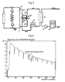
- Fig. 11 shows a plot of the relative whole body efficiency K/V (min -1 ). The period with reversed lines is shown inside a circle. In all other respects, the same discussion applies as is given above.
- Keff/Qb is a figure lower than one, normally for example 0.6 - 0.9. Keff/ Qa should be considerably lower, for example 0.1 - 0.4. Thus, when Cd norm/Cd rev approaches or is lower than a predetermined number, such as 1.2 or 1.5, further calculations should be done for determining if access recirculation is present.
- a simple procedure is to decrease the blood flow Qb somewhat. If the dialysate concentration then decreases, this means that there is no access or fistula recirculation at least at the lower blood flow.
- the measurement should be performed during a time interval, which is considerably larger than 30 seconds so that cardio-pulmonary recirculation has been developed.
- the measurement time for obtaining valid results may be 5 minutes with the needles reversed, while measurements with the needles in correct position may be done in 5 minutes or contiguously during the treatment.
- the method is also applicable to the methods of treatment comprising infusion of a dialysis solution to the blood before or after the dialyzer, called hemofiltration and hemodiafiltration.
- a dialysis solution to the blood before or after the dialyzer, called hemofiltration and hemodiafiltration.
- hemofiltration and hemodiafiltration The result is the same as given above.
- the effective urea clearance obtained according to EP 658 352 relates to blood water, and must therefore be increased by 10 - 13 % before being used in the present formulas.
- Blood urea concentration values obtained from a laboratory relate in general to plasma, and must therefore be decreased by about 7% in order to relate to whole blood.
- all urea concentrations, flow rates and clearances may be used as relating to blood water.
- the effective clearance is then used unchanged, but the calculated access flow will relate to blood water, and has to be increased by 10 - 13 % to relate to whole blood.
- the invention has been described above with reference to use in the human body and using urea as a marker for measuring access flow.
- any other substance present in blood and which can be measured at the dialysate side of the dialyzer may be used according to the invention, such as creatinine, vitamin B12, beta-two-microglobuline, NaCl or any combination of ions.
- Another alternative is to measure conductivity.
- urea concentration may be measured by measuring conductivity differences after passing the urea containing fluid through a urease column, and such conductivity difference can be used directly in place of the concentration values in the equations.
- the invention has been described above with reference to use in the human body. However, the invention can be used in any tube system where a fluid is passed and a portion thereof is taken out for dialysis, such as in beer or wine production.
Landscapes
- Health & Medical Sciences (AREA)
- Heart & Thoracic Surgery (AREA)
- Vascular Medicine (AREA)
- Public Health (AREA)
- Life Sciences & Earth Sciences (AREA)
- Veterinary Medicine (AREA)
- General Health & Medical Sciences (AREA)
- Animal Behavior & Ethology (AREA)
- Engineering & Computer Science (AREA)
- Anesthesiology (AREA)
- Biomedical Technology (AREA)
- Hematology (AREA)
- Urology & Nephrology (AREA)
- Emergency Medicine (AREA)
- Cardiology (AREA)
- Fluid Mechanics (AREA)
- Physics & Mathematics (AREA)
- General Physics & Mathematics (AREA)
- External Artificial Organs (AREA)
- Measurement Of The Respiration, Hearing Ability, Form, And Blood Characteristics Of Living Organisms (AREA)
Claims (18)
- Appareil pour un traitement sanguin extracorporel comprenant :• un dialyseur (11) présentant un premier et un second compartiments (12, 13) séparés par une membrane semi-perméable ;• un circuit sanguin présentant :une ligne de retrait du sang (29) pour raccorder, dans une première condition de fonctionnement, une entrée du premier compartiment (12) à un accès vasculaire d'un patient à un premier point de raccordement (5), etune ligne de retour du sang (30) pour raccorder, dans la première condition de fonctionnement, une sortie du premier compartiment (12) à l'accès vasculaire du patient à un second point de raccordement (6), dans lequel les premier et second points de raccordement sont espacés dans le sens du flux ;• un circuit de liquide de dialyse présentant :l'appareil étant caractérisé en ce qu'il comprend :une ligne d'alimentation pour alimenter un liquide de dialyse dans une entrée du second compartiment (13), etune ligne de résidus pour drainer un liquide résiduel d'une sortie du second compartiment (13),• un moyen d'inversion (28) pour commuter le raccordement de la ligne de retrait du sang (29) et de la ligne de retour du sang (30) à l'accès vasculaire de sorte que, dans une seconde condition de fonctionnement, le premier point de raccordement (5) est en communication fluidique avec la sortie du premier compartiment (12) et le second point de raccordement (6) est en communication fluidique avec l'entrée du premier compartiment (12) ;• un moyen de mesure (20) pour mesurer, dans la première condition de fonctionnement, une première valeur (Cd norm) d'une propriété dans le liquide résiduel, et pour mesurer, dans la seconde condition de fonctionnement, une seconde valeur (Cd rev) de la propriété dans le liquide résiduel, la propriété étant essentiellement proportionnelle à la concentration d'une substance dans le liquide résiduel ; et• un moyen de calcul pour calculer un débit de fluide (Qa) dans l'accès vasculaire à partir des première et seconde valeurs mesurées (Cd norm, Cd rev) de la propriété dans le liquide résiduel.
- Appareil selon la revendication 1, dans lequel la substance est sélectionnée dans le groupe comprenant l'urée, la créatinine, la vitamine B12, la bêta-2-microglobuline et le glucose.
- Appareil selon la revendication 1, dans lequel la substance est un ion sélectionné dans le groupe comprenant Na+, Cl-, Mg++, Ca++, HCO3 -, l'ion acétate, ou toute combinaison de ceux-ci.
- Appareil selon l'une des revendications 1 à 3, dans lequel la propriété est la conductivité du liquide de dialyse.
- Appareil selon l'une des revendications 1 à 3, dans lequel la propriété est la différence de la concentration de la substance entre la sortie et l'entrée du dialyseur (11).
- Appareil selon l'une des revendications 1 à 3, dans lequel la propriété est soit la concentration de la substance dans le sang, soit l'efficacité corporelle totale relative (Kwb/V) définie en tant que rapport entre la clairance corporelle totale Kwb et le volume de distribution de l'urée V.
- Appareil selon l'une des revendications 1 à 6, dans lequel le calcul du débit (Qa) du liquide dans l'accès vasculaire prend en compte un paramètre (K, Keff) indicateur du transfert de la substance à travers la membrane semi-perméable (14).
- Appareil selon la revendication 7, dans lequel le paramètre indicateur du transfert de la substance à travers la membrane semi-perméable (14) est la clairance (K) du dialyseur (11) pour la substance.
- Appareil selon la revendication 8, dans lequel le débit (Qa) du liquide dans le tube est calculé en utilisant l'équation :

- Appareil selon la revendication 7, dans lequel le tube est un accès au flux sanguin pour l'hémodialyse tel qu'un shunt artérioveineux ou une fistule, et dans lequel le paramètre indicateur du transfert de la substance à travers la membrane semi-perméable (14) est la clairance de dialyseur effective Keff, qui prend en compte une recirculation cardiopulmonaire.
- Appareil selon la revendication 10, dans lequel le débit (Qa) du liquide dans l'accès au flux sanguin est calculé en utilisant l'équation :

- Appareil selon la revendication 11, dans lequel la clairance de dialyseur effective Keff est calculée en utilisant l'équation :

où Qd est le débit du liquide de dialyse en aval du dialyseur (11), Cd est la concentration de la substance dans le liquide de dialyse en aval du dialyseur (11), et Cs est la concentration de la substance dans le sang veineux systémique. - Appareil selon la revendication 12, comprenant en outre des moyens pour mesurer la concentration (Cs) de la substance dans le sang veineux systémique, comportant :• des moyens (8, 8a) pour arrêter le flux sanguin dans le circuit sanguin pour une durée suffisante pour permettre à la circulation cardiopulmonaire de s'équilibrer et arrêter le flux de liquide de dialyse ;• des moyens (8, 8a) pour démarrer le flux sanguin dans le circuit sanguin avec une vitesse lente pour remplir la ligne artérielle avec du sang frais avant la mesure ;• des moyens (20) pour mesurer la concentration équilibrée de la substance dans le liquide résiduel à un débit lent ou en ultrafiltration isolée.
- Appareil selon la revendication 12, comprenant en outre des moyens pour évaluer la concentration (Cs) de la substance dans le sang veineux systémique, comportant :• des moyens pour calculer une masse l'urée du corps entier (Murée) dans le corps du patient,• des moyens pour évaluer ou mesurer le volume de distribution (V) de l'urée dans le corps du patient ;• des moyens pour évaluer la concentration (Cs) de la substance dans le sang en divisant la masse de l'urée du corps entier par le volume de distribution.
- Appareil selon l'une des revendications 1 à 14, comprenant en outre :• des moyens (8, 8a) pour modifier le débit sanguin (Qb) ;• des moyens (20) pour surveiller la concentration de ladite substance dans le liquide résiduel ;• des moyens pour détecter une possible recirculation dans la fistule dans la première position en mettant en corrélation un changement dans ladite concentration avec un changement du débit sanguin.
- Appareil selon la revendication 15, comprenant des moyens (8, 8a) pour diminuer le débit sanguin et des moyens (20) pour surveiller une diminution correspondante de la concentration de la substance, l'absence d'une telle diminution étant indicatrice d'une recirculation dans la fistule.
- Appareil selon l'une des revendications 1 à 16, dans lequel le moyen d'inversion comprend un moyen de vanne (28, 28a ; 36, 41) raccordé à la ligne de retrait du sang (29) et à la ligne de retour du sang (30) pour inverser de manière sélective le raccordement de la ligne de retrait du sang (29) et la ligne de retour du sang (30) à l'entrée et à la sortie du premier compartiment (12) du dialyseur (11), le moyen de vanne (28, 28a ; 36, 41) comprenant deux orifices d'entrée et deux orifices de sortie (29a, 30a, 31 a, 32a ; 37, 38, 38, 40) et un élément de vanne (33, 33a ; 43) qui est agencé de telle manière qu'il prend de manière sélective une position de repos dans laquelle tous les quatre orifices d'entrée et de sortie (29a, 30a, 31 a, 32a ; 37, 38, 38, 40) sont interconnectés.
- Appareil selon la revendication 17, comprenant en outre un détecteur d'air (34, 35) agencé entre le moyen de vanne (28, 28a ; 36, 41) et l'extrémité à raccorder à l'accès vasculaire d'un patient d'au moins l'une de la ligne de retrait du sang (29) et de la ligne de retour du sang (30).
Priority Applications (1)
| Application Number | Priority Date | Filing Date | Title |
|---|---|---|---|
| EP09165573.8A EP2198900B1 (fr) | 1998-10-23 | 1999-10-22 | Procédé et dispositif de détection de recirculation d'accès |
Applications Claiming Priority (3)
| Application Number | Priority Date | Filing Date | Title |
|---|---|---|---|
| US10539698P | 1998-10-23 | 1998-10-23 | |
| US105396P | 1998-10-23 | ||
| PCT/SE1999/001915 WO2000024440A1 (fr) | 1998-10-23 | 1999-10-22 | Procede et dispositif de mesure du flux d'acces |
Related Child Applications (2)
| Application Number | Title | Priority Date | Filing Date |
|---|---|---|---|
| EP09165573.8A Division EP2198900B1 (fr) | 1998-10-23 | 1999-10-22 | Procédé et dispositif de détection de recirculation d'accès |
| EP09165573.8 Division-Into | 2009-07-15 |
Publications (2)
| Publication Number | Publication Date |
|---|---|
| EP1124599A1 EP1124599A1 (fr) | 2001-08-22 |
| EP1124599B1 true EP1124599B1 (fr) | 2013-07-24 |
Family
ID=22305607
Family Applications (2)
| Application Number | Title | Priority Date | Filing Date |
|---|---|---|---|
| EP99970926.4A Expired - Lifetime EP1124599B1 (fr) | 1998-10-23 | 1999-10-22 | Dispositif de mesure du flux d'acces lors de dialyse |
| EP09165573.8A Expired - Lifetime EP2198900B1 (fr) | 1998-10-23 | 1999-10-22 | Procédé et dispositif de détection de recirculation d'accès |
Family Applications After (1)
| Application Number | Title | Priority Date | Filing Date |
|---|---|---|---|
| EP09165573.8A Expired - Lifetime EP2198900B1 (fr) | 1998-10-23 | 1999-10-22 | Procédé et dispositif de détection de recirculation d'accès |
Country Status (9)
| Country | Link |
|---|---|
| EP (2) | EP1124599B1 (fr) |
| JP (2) | JP4394288B2 (fr) |
| KR (1) | KR100591574B1 (fr) |
| CN (1) | CN1204930C (fr) |
| AU (1) | AU759593B2 (fr) |
| CA (1) | CA2345965C (fr) |
| HK (1) | HK1040203A1 (fr) |
| NZ (1) | NZ510869A (fr) |
| WO (1) | WO2000024440A1 (fr) |
Cited By (1)
| Publication number | Priority date | Publication date | Assignee | Title |
|---|---|---|---|---|
| US8926542B2 (en) | 2011-04-29 | 2015-01-06 | Medtronic, Inc. | Monitoring fluid volume for patients with renal disease |
Families Citing this family (48)
| Publication number | Priority date | Publication date | Assignee | Title |
|---|---|---|---|---|
| US6648845B1 (en) † | 1998-01-07 | 2003-11-18 | Fresenius Medical Care North America | Method and apparatus for determining hemodialysis parameters |
| SE0100838D0 (sv) * | 2001-03-12 | 2001-03-12 | Jan Sternby | Method and apparatus for needle placement |
| US6676660B2 (en) | 2002-01-23 | 2004-01-13 | Ethicon Endo-Surgery, Inc. | Feedback light apparatus and method for use with an electrosurgical instrument |
| SE0200370D0 (sv) * | 2002-02-08 | 2002-02-08 | Gambro Lundia Ab | Method and apparatus for determining access flow |
| DE10259437B3 (de) * | 2002-12-19 | 2004-09-16 | Fresenius Medical Care Deutschland Gmbh | Verfahren und Vorrichtung zur Bestimmung des Blutflusses in einer blutführenden Leitung |
| WO2005042059A2 (fr) * | 2003-10-31 | 2005-05-12 | Gambro Lundia Ab | Circuit de traitement extracorporel du sang et dispositif d'inversion du courant utilise dans ce circuit |
| JP4573231B2 (ja) * | 2006-11-01 | 2010-11-04 | 日機装株式会社 | 血液浄化装置 |
| FR2911417B1 (fr) | 2007-01-17 | 2009-02-27 | Gambro Lundia Ab | Suivi de l'acces vasculaire d'un patient soumis a des seances successives de traitement extracorporel de sang |
| CN101920049B (zh) * | 2009-06-11 | 2014-03-12 | 四川大学华西医院 | 测定透析通路的再循环率和/或再循环量的方法及系统 |
| US9399091B2 (en) | 2009-09-30 | 2016-07-26 | Medtronic, Inc. | System and method to regulate ultrafiltration |
| WO2011080194A1 (fr) | 2009-12-28 | 2011-07-07 | Gambro Lundia Ab | Dispositif et procédé de contrôle de la vitesse d'écoulement des fluides dans un système cardiovasculaire |
| ES2440366T3 (es) | 2010-04-13 | 2014-01-28 | Gambro Lundia Ab | Conector para un conducto de transporte de fluido de un dispositivo médico |
| CN103889481B (zh) | 2011-08-02 | 2016-03-09 | 美敦力公司 | 带有具有可控的顺应性容积的流动路径的血液透析系统 |
| US10857277B2 (en) | 2011-08-16 | 2020-12-08 | Medtronic, Inc. | Modular hemodialysis system |
| JP5852248B2 (ja) * | 2012-08-30 | 2016-02-03 | テルモ株式会社 | 体外循環装置、制御装置及びその制御方法 |
| US10905816B2 (en) | 2012-12-10 | 2021-02-02 | Medtronic, Inc. | Sodium management system for hemodialysis |
| US9623164B2 (en) | 2013-02-01 | 2017-04-18 | Medtronic, Inc. | Systems and methods for multifunctional volumetric fluid control |
| US10010663B2 (en) | 2013-02-01 | 2018-07-03 | Medtronic, Inc. | Fluid circuit for delivery of renal replacement therapies |
| US10850016B2 (en) | 2013-02-01 | 2020-12-01 | Medtronic, Inc. | Modular fluid therapy system having jumpered flow paths and systems and methods for cleaning and disinfection |
| US10543052B2 (en) | 2013-02-01 | 2020-01-28 | Medtronic, Inc. | Portable dialysis cabinet |
| US9827361B2 (en) | 2013-02-02 | 2017-11-28 | Medtronic, Inc. | pH buffer measurement system for hemodialysis systems |
| DE102013103221A1 (de) * | 2013-03-28 | 2014-10-02 | B. Braun Avitum Ag | Verfahren zur Erfassung einer Rezirkulation in einem arteriovenösen Shunt während laufender Hämodialyse und Dialysesystem |
| DE102013103220A1 (de) * | 2013-03-28 | 2014-10-02 | B. Braun Avitum Ag | Verfahren und Vorrichtung zur Bestimmung eines Rezirkulationszustands |
| EP2792377A1 (fr) | 2013-04-15 | 2014-10-22 | Gambro Lundia AB | Infrastructure médicale et appareil de supervision médicale pour la surveillance de patients sur une pluralité de sessions de traitement sanguin extracorporel |
| JP6312118B2 (ja) * | 2013-05-16 | 2018-04-18 | 学校法人東京理科大学 | 電気特性測定装置、電気特性測定方法およびプログラム |
| EP3102107A4 (fr) | 2013-11-04 | 2018-02-07 | Medtronic, Inc. | Procédé et dispositif pour gérer des volumes de fluides dans le corps |
| DE102013018444A1 (de) * | 2013-11-05 | 2015-05-07 | Novalung Gmbh | Vorrichtung mit einer Fluidpumpe, mindestens zwei Bauchdeckenzugängen und Fluidpumpe und Bauchdecke verbindenden Schläuchen |
| US9713665B2 (en) | 2014-12-10 | 2017-07-25 | Medtronic, Inc. | Degassing system for dialysis |
| US10874787B2 (en) | 2014-12-10 | 2020-12-29 | Medtronic, Inc. | Degassing system for dialysis |
| US9895479B2 (en) | 2014-12-10 | 2018-02-20 | Medtronic, Inc. | Water management system for use in dialysis |
| US10098993B2 (en) | 2014-12-10 | 2018-10-16 | Medtronic, Inc. | Sensing and storage system for fluid balance |
| JP6559484B2 (ja) * | 2015-07-06 | 2019-08-14 | 日機装株式会社 | 血液浄化装置及びその血液浄化装置によるアクセス血管の流量算出方法 |
| DE102015016854A1 (de) * | 2015-12-23 | 2017-06-29 | Fresenius Medical Care Deutschland Gmbh | Dialysegerät mit Mitteln zur Erkennung einer Shunt-Rezirkulation |
| US10994064B2 (en) | 2016-08-10 | 2021-05-04 | Medtronic, Inc. | Peritoneal dialysate flow path sensing |
| US11013843B2 (en) | 2016-09-09 | 2021-05-25 | Medtronic, Inc. | Peritoneal dialysis fluid testing system |
| US11992589B2 (en) * | 2016-10-03 | 2024-05-28 | Gambro Lundia Ab | Measuring access flow rate by use of blood treatment machine |
| JP7354839B2 (ja) | 2017-10-06 | 2023-10-03 | ニプロ株式会社 | 流路切り換え装置 |
| JP6914803B2 (ja) * | 2017-10-17 | 2021-08-04 | 日機装株式会社 | 血液浄化装置 |
| JP6997582B2 (ja) * | 2017-10-17 | 2022-01-17 | 日機装株式会社 | 血液浄化装置 |
| CN107802906B (zh) * | 2017-11-21 | 2023-09-22 | 四川大学华西医院 | 一种血液净化系统 |
| US11278654B2 (en) | 2017-12-07 | 2022-03-22 | Medtronic, Inc. | Pneumatic manifold for a dialysis system |
| US11110215B2 (en) | 2018-02-23 | 2021-09-07 | Medtronic, Inc. | Degasser and vent manifolds for dialysis |
| CN109084856B (zh) * | 2018-07-19 | 2021-06-04 | 中国神华能源股份有限公司 | 开式循环水系统的流量测定方法 |
| US11806457B2 (en) | 2018-11-16 | 2023-11-07 | Mozarc Medical Us Llc | Peritoneal dialysis adequacy meaurements |
| US11806456B2 (en) | 2018-12-10 | 2023-11-07 | Mozarc Medical Us Llc | Precision peritoneal dialysis therapy based on dialysis adequacy measurements |
| JP7435017B2 (ja) * | 2020-02-26 | 2024-02-21 | ニプロ株式会社 | 透析装置、透析患者の心拍出量の測定方法、算出装置及びコンピュータプログラム |
| CN113694280B (zh) * | 2021-09-02 | 2023-05-05 | 山东威高血液净化制品股份有限公司 | 一种实时监控体外透析器中毒素含量分布的方法 |
| US11965763B2 (en) | 2021-11-12 | 2024-04-23 | Mozarc Medical Us Llc | Determining fluid flow across rotary pump |
Family Cites Families (17)
| Publication number | Priority date | Publication date | Assignee | Title |
|---|---|---|---|---|
| DE3720665A1 (de) * | 1987-06-23 | 1989-01-05 | Schael Wilfried | Vorrichtung zur haemodialyse und haemofiltration |
| US4995268A (en) * | 1989-09-01 | 1991-02-26 | Ash Medical System, Incorporated | Method and apparatus for determining a rate of flow of blood for an extracorporeal blood therapy instrument |
| US5312550B1 (en) | 1992-04-27 | 1996-04-23 | Robert L Hester | Method for detecting undesired dialysis recirculation |
| EP0590810B1 (fr) | 1992-09-30 | 1998-07-15 | Cobe Laboratories, Inc. | ContrÔleur de recirculation utilisant la mesure différentielle de la conductibilité |
| GB2276566A (en) | 1993-03-24 | 1994-10-05 | Saitekku Kabushiki Kaisha | Haemodialyser unit |
| FR2713937B1 (fr) | 1993-12-17 | 1996-05-31 | Hospal Ind | Procédé de détermination d'un paramètre significatif du progrès d'un traitement extracorporel de sang. |
| IT1274841B (it) * | 1994-07-18 | 1997-07-25 | Bellco Spa | Apparecchiatura di tipo perfezionato per trattamenti di dialisi. |
| US5685989A (en) | 1994-09-16 | 1997-11-11 | Transonic Systems, Inc. | Method and apparatus to measure blood flow and recirculation in hemodialysis shunts |
| US5453576A (en) | 1994-10-24 | 1995-09-26 | Transonic Systems Inc. | Cardiovascular measurements by sound velocity dilution |
| DE19528907C1 (de) * | 1995-08-05 | 1996-11-07 | Fresenius Ag | Vorrichtung zur Ermittlung hämodynamischer Parameter während einer extrakorporalen Blutbehandlung |
| DE19541783C1 (de) * | 1995-11-09 | 1997-03-27 | Fresenius Ag | Verfahren zum Betreiben einer Blutbehandlungsvorrichtung zur Ermittlung hämodynamischer Parameter während einer extrakorporalen Blutbehandlung und Vorrichtung zur Ermittlung hämodynamischer Parameter während einer extrakorporalen Blutbehandlung |
| IT1288767B1 (it) * | 1996-10-18 | 1998-09-24 | Hospal Dasco Spa | Metodo di determinazione del valore del ricircolo di una sospensione sottoposta a trattamento. |
| DE19702441C1 (de) * | 1997-01-24 | 1998-02-26 | Fresenius Medical Care De Gmbh | Verfahren zur Bestimmung der Rezirkulation während einer extrakorporalen Blutbehandlung und Vorrichtung zur Durchführung des Verfahrens |
| SE9702074D0 (sv) | 1997-06-02 | 1997-06-02 | Gambro Ab | Method and device for calculating dialysis efficiency |
| SE513034C2 (sv) | 1997-06-02 | 2000-06-19 | Gambro Lundia Ab | Metod och anordning för beräkning av dialyseffektivitet |
| DE19809945C2 (de) * | 1998-03-07 | 2002-02-21 | Fresenius Medical Care De Gmbh | Vorrichtung zur Bereitstellung von Dialysierflüssigkeit mit einer Einrichtung zur Überwachung ausgewählter Parameter der Dialysierflüssigkeit und Verfahren zur Überwachung ausgewählter Parameter der Dialysierflüssigkeit bei einer Dialysebehandlung |
| US5894011A (en) | 1998-06-24 | 1999-04-13 | Prosl; Frank R. | Flow reversing device for hemodialysis |
-
1999
- 1999-10-22 EP EP99970926.4A patent/EP1124599B1/fr not_active Expired - Lifetime
- 1999-10-22 AU AU14299/00A patent/AU759593B2/en not_active Ceased
- 1999-10-22 NZ NZ510869A patent/NZ510869A/en not_active IP Right Cessation
- 1999-10-22 CN CNB998125024A patent/CN1204930C/zh not_active Expired - Fee Related
- 1999-10-22 JP JP2000578044A patent/JP4394288B2/ja not_active Expired - Fee Related
- 1999-10-22 KR KR1020017004947A patent/KR100591574B1/ko not_active IP Right Cessation
- 1999-10-22 CA CA2345965A patent/CA2345965C/fr not_active Expired - Fee Related
- 1999-10-22 WO PCT/SE1999/001915 patent/WO2000024440A1/fr active IP Right Grant
- 1999-10-22 EP EP09165573.8A patent/EP2198900B1/fr not_active Expired - Lifetime
-
2002
- 2002-03-15 HK HK02102019.1A patent/HK1040203A1/zh unknown
-
2009
- 2009-08-17 JP JP2009188465A patent/JP5275170B2/ja not_active Expired - Fee Related
Cited By (3)
| Publication number | Priority date | Publication date | Assignee | Title |
|---|---|---|---|---|
| US8926542B2 (en) | 2011-04-29 | 2015-01-06 | Medtronic, Inc. | Monitoring fluid volume for patients with renal disease |
| US8951219B2 (en) | 2011-04-29 | 2015-02-10 | Medtronic, Inc. | Fluid volume monitoring for patients with renal disease |
| US9597440B2 (en) | 2011-04-29 | 2017-03-21 | Medtronic, Inc. | Fluid volume monitoring for patients with renal disease |
Also Published As
| Publication number | Publication date |
|---|---|
| EP2198900B1 (fr) | 2016-02-10 |
| JP5275170B2 (ja) | 2013-08-28 |
| AU759593B2 (en) | 2003-04-17 |
| HK1040203A1 (zh) | 2002-05-31 |
| CA2345965A1 (fr) | 2000-05-04 |
| CA2345965C (fr) | 2010-12-14 |
| EP2198900A3 (fr) | 2011-02-23 |
| CN1204930C (zh) | 2005-06-08 |
| NZ510869A (en) | 2003-08-29 |
| JP2002528181A (ja) | 2002-09-03 |
| EP1124599A1 (fr) | 2001-08-22 |
| CN1324255A (zh) | 2001-11-28 |
| JP4394288B2 (ja) | 2010-01-06 |
| KR20010083917A (ko) | 2001-09-03 |
| KR100591574B1 (ko) | 2006-06-20 |
| WO2000024440A1 (fr) | 2000-05-04 |
| AU1429900A (en) | 2000-05-15 |
| JP2009268922A (ja) | 2009-11-19 |
| EP2198900A2 (fr) | 2010-06-23 |
Similar Documents
| Publication | Publication Date | Title |
|---|---|---|
| EP1124599B1 (fr) | Dispositif de mesure du flux d'acces lors de dialyse | |
| US6726647B1 (en) | Method and device for measuring access flow | |
| US7815852B2 (en) | Method, apparatus and software program for measurement of a parameter relating to a heart-lung system of a mammal | |
| EP0928614B1 (fr) | Procédé de détermination de paramètres d'hémodialyse | |
| US20130338560A1 (en) | Method and apparatus for determining access flow | |
| Petitclerc et al. | Non-invasive monitoring of effective dialysis dose delivered to the haemodialysis patient | |
| AU2003213543A1 (en) | Switch valve | |
| MXPA01003936A (en) | Method and device for measuring access flow | |
| Roca-Tey et al. | Alberto Magnasco1, Sandro Alloatti2, Carlo Martinoli3, Paolo Solari1. 1Dialysis, Hospital, Sestri Levante, Italy; 2Dialysis, Hospital, Aosta, Italy; 3Radiology, Genoa University, Genoa, Italy A good test for monitoring blood flow (Qa) must be accurate, rapid and economical in order to allow frequent easy measurements. A constant |
Legal Events
| Date | Code | Title | Description |
|---|---|---|---|
| PUAI | Public reference made under article 153(3) epc to a published international application that has entered the european phase |
Free format text: ORIGINAL CODE: 0009012 |
|
| 17P | Request for examination filed |
Effective date: 20010511 |
|
| AK | Designated contracting states |
Kind code of ref document: A1 Designated state(s): AT BE CH CY DE DK ES FI FR GB GR IE IT LI LU MC NL PT SE |
|
| AX | Request for extension of the european patent |
Free format text: AL;LT;LV;MK;RO;SI |
|
| RTI1 | Title (correction) |
Free format text: DEVICE FOR MEASURING ACCESS FLOW BY DIALYSIS |
|
| GRAP | Despatch of communication of intention to grant a patent |
Free format text: ORIGINAL CODE: EPIDOSNIGR1 |
|
| GRAJ | Information related to disapproval of communication of intention to grant by the applicant or resumption of examination proceedings by the epo deleted |
Free format text: ORIGINAL CODE: EPIDOSDIGR1 |
|
| RIN1 | Information on inventor provided before grant (corrected) |
Inventor name: NILSSON, EDDIE Inventor name: ASBRINK, PERRY Inventor name: MISHKIN, GARY Inventor name: STERNBY, JAN |
|
| APBN | Date of receipt of notice of appeal recorded |
Free format text: ORIGINAL CODE: EPIDOSNNOA2E |
|
| APBR | Date of receipt of statement of grounds of appeal recorded |
Free format text: ORIGINAL CODE: EPIDOSNNOA3E |
|
| APAF | Appeal reference modified |
Free format text: ORIGINAL CODE: EPIDOSCREFNE |
|
| RAP1 | Party data changed (applicant data changed or rights of an application transferred) |
Owner name: GAMBRO LUNDIA AB |
|
| APBT | Appeal procedure closed |
Free format text: ORIGINAL CODE: EPIDOSNNOA9E |
|
| GRAP | Despatch of communication of intention to grant a patent |
Free format text: ORIGINAL CODE: EPIDOSNIGR1 |
|
| GRAS | Grant fee paid |
Free format text: ORIGINAL CODE: EPIDOSNIGR3 |
|
| GRAA | (expected) grant |
Free format text: ORIGINAL CODE: 0009210 |
|
| AK | Designated contracting states |
Kind code of ref document: B1 Designated state(s): AT BE CH CY DE DK ES FI FR GB GR IE IT LI LU MC NL PT SE |
|
| REG | Reference to a national code |
Ref country code: GB Ref legal event code: FG4D |
|
| REG | Reference to a national code |
Ref country code: CH Ref legal event code: EP |
|
| REG | Reference to a national code |
Ref country code: AT Ref legal event code: REF Ref document number: 623027 Country of ref document: AT Kind code of ref document: T Effective date: 20130815 |
|
| REG | Reference to a national code |
Ref country code: IE Ref legal event code: FG4D |
|
| REG | Reference to a national code |
Ref country code: DE Ref legal event code: R096 Ref document number: 69944837 Country of ref document: DE Effective date: 20130919 |
|
| REG | Reference to a national code |
Ref country code: AT Ref legal event code: MK05 Ref document number: 623027 Country of ref document: AT Kind code of ref document: T Effective date: 20130724 |
|
| REG | Reference to a national code |
Ref country code: NL Ref legal event code: VDEP Effective date: 20130724 |
|
| PG25 | Lapsed in a contracting state [announced via postgrant information from national office to epo] |
Ref country code: BE Free format text: LAPSE BECAUSE OF FAILURE TO SUBMIT A TRANSLATION OF THE DESCRIPTION OR TO PAY THE FEE WITHIN THE PRESCRIBED TIME-LIMIT Effective date: 20130724 Ref country code: SE Free format text: LAPSE BECAUSE OF FAILURE TO SUBMIT A TRANSLATION OF THE DESCRIPTION OR TO PAY THE FEE WITHIN THE PRESCRIBED TIME-LIMIT Effective date: 20130724 Ref country code: AT Free format text: LAPSE BECAUSE OF FAILURE TO SUBMIT A TRANSLATION OF THE DESCRIPTION OR TO PAY THE FEE WITHIN THE PRESCRIBED TIME-LIMIT Effective date: 20130724 Ref country code: PT Free format text: LAPSE BECAUSE OF FAILURE TO SUBMIT A TRANSLATION OF THE DESCRIPTION OR TO PAY THE FEE WITHIN THE PRESCRIBED TIME-LIMIT Effective date: 20131125 Ref country code: CY Free format text: LAPSE BECAUSE OF NON-PAYMENT OF DUE FEES Effective date: 20130526 |
|
| PG25 | Lapsed in a contracting state [announced via postgrant information from national office to epo] |
Ref country code: FI Free format text: LAPSE BECAUSE OF FAILURE TO SUBMIT A TRANSLATION OF THE DESCRIPTION OR TO PAY THE FEE WITHIN THE PRESCRIBED TIME-LIMIT Effective date: 20130724 Ref country code: GR Free format text: LAPSE BECAUSE OF FAILURE TO SUBMIT A TRANSLATION OF THE DESCRIPTION OR TO PAY THE FEE WITHIN THE PRESCRIBED TIME-LIMIT Effective date: 20131025 Ref country code: ES Free format text: LAPSE BECAUSE OF FAILURE TO SUBMIT A TRANSLATION OF THE DESCRIPTION OR TO PAY THE FEE WITHIN THE PRESCRIBED TIME-LIMIT Effective date: 20130724 Ref country code: NL Free format text: LAPSE BECAUSE OF FAILURE TO SUBMIT A TRANSLATION OF THE DESCRIPTION OR TO PAY THE FEE WITHIN THE PRESCRIBED TIME-LIMIT Effective date: 20130724 |
|
| PG25 | Lapsed in a contracting state [announced via postgrant information from national office to epo] |
Ref country code: CY Free format text: LAPSE BECAUSE OF NON-PAYMENT OF DUE FEES Effective date: 20130724 |
|
| PG25 | Lapsed in a contracting state [announced via postgrant information from national office to epo] |
Ref country code: DK Free format text: LAPSE BECAUSE OF FAILURE TO SUBMIT A TRANSLATION OF THE DESCRIPTION OR TO PAY THE FEE WITHIN THE PRESCRIBED TIME-LIMIT Effective date: 20130724 |
|
| PG25 | Lapsed in a contracting state [announced via postgrant information from national office to epo] |
Ref country code: MC Free format text: LAPSE BECAUSE OF FAILURE TO SUBMIT A TRANSLATION OF THE DESCRIPTION OR TO PAY THE FEE WITHIN THE PRESCRIBED TIME-LIMIT Effective date: 20130724 |
|
| PLBE | No opposition filed within time limit |
Free format text: ORIGINAL CODE: 0009261 |
|
| REG | Reference to a national code |
Ref country code: CH Ref legal event code: PL |
|
| STAA | Information on the status of an ep patent application or granted ep patent |
Free format text: STATUS: NO OPPOSITION FILED WITHIN TIME LIMIT |
|
| 26N | No opposition filed |
Effective date: 20140425 |
|
| REG | Reference to a national code |
Ref country code: IE Ref legal event code: MM4A |
|
| PG25 | Lapsed in a contracting state [announced via postgrant information from national office to epo] |
Ref country code: CH Free format text: LAPSE BECAUSE OF NON-PAYMENT OF DUE FEES Effective date: 20131031 Ref country code: LI Free format text: LAPSE BECAUSE OF NON-PAYMENT OF DUE FEES Effective date: 20131031 |
|
| REG | Reference to a national code |
Ref country code: DE Ref legal event code: R097 Ref document number: 69944837 Country of ref document: DE Effective date: 20140425 |
|
| PG25 | Lapsed in a contracting state [announced via postgrant information from national office to epo] |
Ref country code: IE Free format text: LAPSE BECAUSE OF NON-PAYMENT OF DUE FEES Effective date: 20131022 |
|
| PG25 | Lapsed in a contracting state [announced via postgrant information from national office to epo] |
Ref country code: LU Free format text: LAPSE BECAUSE OF NON-PAYMENT OF DUE FEES Effective date: 20131022 |
|
| REG | Reference to a national code |
Ref country code: FR Ref legal event code: PLFP Year of fee payment: 18 |
|
| PGFP | Annual fee paid to national office [announced via postgrant information from national office to epo] |
Ref country code: GB Payment date: 20160926 Year of fee payment: 18 |
|
| PGFP | Annual fee paid to national office [announced via postgrant information from national office to epo] |
Ref country code: FR Payment date: 20160926 Year of fee payment: 18 |
|
| PGFP | Annual fee paid to national office [announced via postgrant information from national office to epo] |
Ref country code: DE Payment date: 20161031 Year of fee payment: 18 |
|
| PGFP | Annual fee paid to national office [announced via postgrant information from national office to epo] |
Ref country code: IT Payment date: 20161019 Year of fee payment: 18 |
|
| REG | Reference to a national code |
Ref country code: DE Ref legal event code: R119 Ref document number: 69944837 Country of ref document: DE |
|
| GBPC | Gb: european patent ceased through non-payment of renewal fee |
Effective date: 20171022 |
|
| REG | Reference to a national code |
Ref country code: FR Ref legal event code: ST Effective date: 20180629 |
|
| PG25 | Lapsed in a contracting state [announced via postgrant information from national office to epo] |
Ref country code: GB Free format text: LAPSE BECAUSE OF NON-PAYMENT OF DUE FEES Effective date: 20171022 Ref country code: DE Free format text: LAPSE BECAUSE OF NON-PAYMENT OF DUE FEES Effective date: 20180501 |
|
| PG25 | Lapsed in a contracting state [announced via postgrant information from national office to epo] |
Ref country code: FR Free format text: LAPSE BECAUSE OF NON-PAYMENT OF DUE FEES Effective date: 20171031 |
|
| PG25 | Lapsed in a contracting state [announced via postgrant information from national office to epo] |
Ref country code: IT Free format text: LAPSE BECAUSE OF NON-PAYMENT OF DUE FEES Effective date: 20171022 |