Background of the Invention
1. Field of the Invention
The present invention relates to a piezoelectric
ceramics to be applicable widely in the field of a resonator,
a pressure sensor, or the like.
2. Description of the Related Art
A piezoelectric element is a material having the
piezoelectric effect of changing the electric polarization by
the external stress, and the inverse piezoelectric effect of
generating strain by the electric field application. The
piezoelectric element is adopted in a sensor, a resonator, an
actuator, or the like, for measuring the pressure or the
deformation.
Most of piezoelectric materials practically used now
are commonly ferroelectric elements having a perovskite
structure based on PZT (PbZrO3-PbTiO3 solid solution) of a
tetragonal system or a rhombohedral system, or based on PT
(PbTiO3) of a tetragonal system. By adding various sub
components thereto, various characteristics are provided as
requested.
However, most of the PZT-based or PT-based
piezoelectric materials have a 300 to 350°C Curie temperature
in a practical composition. In contrast, since a process
temperature in a present soldering step is, in general, 230 to
250°C, a piezoelectric material with a 300 to 350°C Curie
temperature can easily generate characteristic deterioration
in the soldering step. Besides, in the case where a solder not
containing a lead (lead-free solder) is used practically, the
process temperature in the soldering step is further higher.
Therefore, it is extremely important to have the Curie
temperature of the piezoelectric material higher.
Moreover, since the lead-basedpiezoelectric materials
contain a large content (about 60 to 70wt%) of a lead oxide (PbO)
having an extremely high volatility even at a low temperature,
they are not preferable from the viewpoints of ecology and
pollution prevention. Specifically, in producing the lead-based
piezoelectric materials as ceramics or a single crystal,
a heat treatment such as firing and melting is inevitable, and
thus the lead oxide as a volatile component can be volatilized
and dispersed by an extremely large amount in an industrial
level. Furthermore, although the lead oxide discharged in the
production step can be collected, most of the lead oxide
contained in the piezoelectric materials dispatched to the
market as industrial merchandises cannot be collected in the
present situation. Therefore, in the case where it is
discharged widely in the environment, it should inevitably be
the cause of pollution.
As a lead-free piezoelectric material, for example,
BaTiO3 of a perovskite structure belonging to a tetragonal
system is well known. However, since it has a low Curie
temperature of 120°C, it is not practical. Moreover, JP-A-9-100156
discloses a (1-x) (Bi1/2Na1/2) TiO3-xNaNbO3 solid solution
of a perovskite structure; however, those having a Curie
temperature higher than 370°C are not included.
As a piezoelectric element capable of having a Curie
temperature of 500°C or more, for example, a bismuth layer
compound (a compound shaped in bismuth layer) is known. Since
the bismuth layer compound has a high Curie temperature, once
it is polarized, it is thermally stable and thus characteristics
sufficient for a sensor for high temperature can be obtained.
On the other hand, a problem is involved in that sufficient
piezoelectric characteristics can be hardly obtained for
difficulty of the polarization itself. Furthermore, a
lead-free bismuth layer compound involves a problem in that Qmax
important in the case where it is adopted in a resonator is small.
Qmax is tanmax wherein max represents the maximum value of
the phase angle. That is, it is the maximum value of Q (= |X|/R)
between the resonant frequency and the antiresonant frequency
wherein X denotes the reactance and R denotes the resistance.
With larger Qmax, the vibration can be stabilized, and further,
the vibration is enabled with a low voltage.
A report on improvement of Qmax of a lead-free bismuth
layer compound is disclosed on pages 97-98 of the lecture
abstracts of the 16th Meeting on Ferroelectric Materials and
Their Applications (May 26-29, 1999). In this abstract,
(Sr1-xMex)Bi4Ti4O15, wherein Me represents Ba, Ca, La, Sm, or Gd,
with Ba and Ca added in the range of x ≤ 0.1, Sm and Gd X ≤ 0.4,
and La x ≤ 0.5, is provided as the lead-free bismuth layer
compound. In the abstract, Qmax is measured in the thickness
extensional fundamental vibration mode. FIG. 2 show the
improvement of Qmax by addition of an La, and decline of Qmax
by addition of Ba or Ca.
In the case of adopting piezoelectric ceramics in a
resonator or a filter, small temperature dependency of the
resonant frequency is required. However; piezoelectric
ceramics having Qmax sufficiently large for the practical use
as a resonator and small temperature dependency of the resonant
frequency has not been reported so far.
Summary of the Invention
An object of the present invention is to provide
lead-free piezoelectric ceramics having a high Curie
temperature, the excellent piezoelectric characteristics, and
small temperature dependency of the resonant frequency.
The above-mentioned object can be achieved by the
invention of the below-mentioned items (1) to (5).
Brief Description of the Drawings
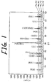
FIG. 1 is an X ray diffraction chart of piezoelectric
ceramics for the samples Nos. 102-105.
FIG. 2 is a scanning electron microscope photograph of
Sample No. 102 in TABLE 2, showing the grain structure.
FIG. 3 is a scanning electron microscope photograph of
Sample No, 103 in TABLE 2, showing the grain structure.
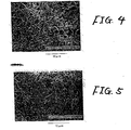
FIG. 4 is a scanning electron microscope photograph of
Sample No. 104 in TABLE 2, showing the grain structure.
FIG. 5 is a scanning electron microscope photograph of
Sample No. 105 in TABLE 2, showing the grain structure.
Detailed Description of the Preferred Embodiments
Piezoelectric ceramics according to the invention
comprise a bismuth layer compound containing MII, Bi, Ti, Ln
and O. MII represents at least one element selected from the
group consisting of Sr, Ba and Ca, and Ln represents at least
one element selected from the group consisting of lanthanoids.
In other words, the piezoelectric ceramics of the present
invention are composite oxide containing MIIBi4Ti4O15 typed
crystals.
In the piezoelectric ceramic according to the present
invention, the mole ratio of 4Bi/Ti is preferably 4.000 < 4Bi/Ti
≤ 4.030. By containing Bi richer than M11Bi4Ti4O15 of the
stoichiometric composition, Qmax can be improved. However, if
4Bi/Ti is more than 4.03, insulation resistance is lowered so
that polarization process becomes difficult. Moreover, Qmax
is lowered on the contrary. In order to have the improvement
ratio of Qmax higher, it is preferable that 4.010 < 4Bi/Ti.
Moreover, in order to further restrain decline of the insulation
resistance, it is preferable that 4Bi/Ti ≤ 4.028.
Further, in order to improve Qmax, the piezoelectric
ceramics according to the present invention contain lanthanoid
oxide. The lanthanoids include La, Ce, Pr, Nd, Pm, Sm, Eu, Gd,
Tb, Dy, Ho, Er, Tm, Yb and Lu. Among them, at least one selected
from the group consisting of La, Nd, Sm, Gd, Dy, Ho, Er and Yb
is preferable, and La is most preferable. The mole ratio of
Ln/(Ln+MII) in the piezoelectric ceramics of the present
invention is 0 < Ln/ (Ln+MII) < 0.5, and is preferably 0.03 ≤
Ln/ (Ln+MII) ≤ 0.3. If the Ln/ (Ln+MII) is too large, Qmax is
lowered on the contrary. Improvement of Qmax by addition of
Ln oxide is considered to be owing to improvement of the
sintering property. Ln oxide-free MIIBi4Ti4O15 based ceramics,
in particular, CaBi4Ti4O15 based ceramics are hardly polarized;
however, it can be improved by addition of Ln oxide.
In addition to Ln oxide, it is preferable that
piezoelectric ceramics according to the present invention
contain Y oxide. By adding Y oxide in combination with Ln oxide,
temperature characteristics of the material at the resonant
frequency can be improved. Further, sufficiently large Qmax
can be obtained. A content of Y oxide is preferably 0.5wt% or
less, more preferably 0.4wt% or less in terms of Y2O3. If the
content of Y oxide is too large, Qmax is lowered. In contrast,
in order to sufficiently obtain the effect of adding Y oxide,
it is preferable to contain Y oxide by 0.1wt% or more, in
particular, by 0.2wt.% or more in terms of Y2O3.
By containing Mn oxide and/or Co oxide in the
piezoelectric ceramics according to the present invention, Qmax
can be further improved. In particular, by adding Mn oxide in
combination with Ln oxide, Qmax can be improved remarkably.
In order to sufficiently obtain the effect of adding
Mn oxide, it is preferable to contain Mn oxide by 0.02wt% or
more in terms of MnO. In the case where it is contained by
0.03wt% or more, the improvement in Qmax can be particularly
high. However, since the insulation resistance is made lower
so that the polarization process becomes difficult if the
content of Mn oxide is too high, the content of Mn oxide is
preferably less than 0.62wt%, more preferably 0,60wt% or less,
and further preferably 0.43wt% or less in terms of MnO. In
contrast, in order to sufficiently obtain the effect of adding
Mn oxide, it is preferable to contain Mn oxide by 0.02wt% or
more in terms of MnO. In the case where it is contained by
0.03wt% or more, improvement in Qmax can be particularly high.
As mentioned above, Qmax can also be improved by
containing Co oxide. In order to sufficiently obtain the effect
of adding Co oxide, it is preferable that the content is 0.1wt%
or more in terms of CoO. However, if the content of Co oxide
is excessive, insulation resistance is made larger so that
polarization process becomes difficult. Therefore, the
content in terms of CoO is preferably less than 0.7wt%, and more
preferably 0.5wt% or less.
It is preferable that the mole ratio in MII represented
as SrxBayCaz (wherein x + y + z = 1) is:
0 ≤ x < 1,
0 ≤ y ≤ 0.9, and
0 ≤ z ≤ 1.
If the ratio y of Ba in MII is too high, the piezoelectric ceramics
can be easily melted at the time of firing.
It is preferable that the piezoelectric ceramics
according to the present invention contain MIIBi4Ti4O15 typed
crystals of a bismuth layer compound, and substantially
comprises the crystals. However, it is also possible that they
are not completely homogeneous and contain a different phase.
In the piezoelectric ceramics, Ln is considered to substitute
mainly the MII site in the MIIBi4Ti4O15 typed crystals, but it can
partially substitute another site, or it can exist partially
in the grain boundary.
The entire composition of the piezoelectric ceramic
according to the present invention can be, in general,
(M11 1-aLna)BibTi4O with 4Bi/Ti (=b) in the above-mentioned range,
and with MnO or CoO added thereto in the case where Mn oxide
or Co oxide is contained, but it can be deviated therefrom. For
example, a ratio of (M11 + Ln) with respect to Ti may be deviated
by about ±5% from the stoichiometric composition. Moreover,
the oxygen amount can be varied depending upon the valence
number of the metal element or the oxygen defect.
Further, the entire composition of the piezoelectric
ceramics according to the present invention can be, in general,
(MII 1-xLnx)Bi4Ti4O15 with adding Y2O3, but it can be deviated
therefrom. For example, the ratio of (MII + Ln) with respect
to Ti and the ratio of Bi with respect to Ti may be deviated
by about ±5% from the stoichiometric composition. Moreover,
as above, the oxygen content can be varied depending upon the
valence number of the metal element, the oxygen defect or the
like.
In the piezoelectric ceramics according to the present
invention, Pb oxide, Cr oxide, Fe oxide, or the like may be
contained as an impurity or a minor additive. It is preferable
that the content of these oxides is 0.5wt% or less with respect
to the entirety in terms of an oxide of the stoichiometric
composition such as Pbo, Cr2O3, and Fe2O3. Further, it is
preferable that the total of these oxides is 0.5wt% or less.
If the content of these oxides is too large, the effect of the
present invention may be deteriorated. Although it is most
preferable that Pb is not contained in the piezoelectric
ceramics according to the present invention, a content of the
above-mentioned range is not substantially problematic.
Crystal grains of the piezoelectric ceramics according
to the present invention are spindle-shaped or needle-shaped.
The average size of the crystal particle is not particularly
limited, but preferably 1 to 10 µm, more preferably 3 to 5 µm
in the longitudinal direction.
The Curie temperature of the piezoelectric ceramics
according to the present invention is at least 380°C or more,
and it can easily be 430°C or more.
The piezoelectric ceramics according to the present
invention are suitable for a resonator, a high temperature
sensor, an actuator, or the like. For the good temperature
characteristics of the resonant frequency, it is particularly.
suitable for a resonator.
The application mode of the piezoelectric ceramics
according to the present invention is not particularly limited;
therefore, any mode such as thickness extensional vibration
mode, and thickness sliding vibration can be used. In the
thickness extensional fundamental vibration mode, relatively
high Qmax can be obtained. However, since much spurious
vibration is generated, consequently the vibration stability
is slightly lowered. In contrast, in third harmonic mode of
the thickness extensional vibration mode, Qmax is smaller but
the spurious vibration can be reduced. In contrast, in
thickness sliding fundamental vibration, the spurious
vibration is small as well as sufficiently large Qmax can be
obtained.
According to the study by the present inventors, in the
case of the thickness sliding vibration, it was learned that
the temperature characteristics of the resonant frequency is
relatively steep and the temperature dependency of the
oscillating frequency is relatively large. As a result of
further experiments, it was found out that the temperature
characteristics of the resonant frequency can be flattened
considerably by setting a mole ratio in MII:
x/6 + 0.2 ≤ y ≤ 0.8.
That is, by using at least Ba and/or Ca as MII and having the
ratio of Ba + Ca in MII in a predetermined range.
Although the case of piezoelectric ceramics containing
M11Bi4Ti4O15 typed crystals have been explained so far, Qmax can
be improved by deviating a ratio of contained metal elements
from the stoichiometric composition also in piezoelectric
ceramics containing, for example, M11Bi2Nb2O9 typed crystals,
M11Bi2Ta2O9 typed crystal, Bi3TiNbO9 typed crystals, Bi4Ti3O12
typed crystals, Bi1.5MI 0.5Ti4O15 typed crystals (wherein MI is at
least one selected from the group consisting of alkaline metal
elements such as Na and K), or an MII 2Bi4Ti5O18 typed crystals.
Production Method
An example of a method for producing the piezoelectric
ceramics according to the present invention will be explained.
First, as starting materials, powders of oxide, or a
compound to be converted to oxide by firing, such as carbonate,
hydroxide, oxalate, and nitrate, specifically, MIICO3, Bi2O3,
TiO2, La2O3, MnO2, MnCO3, Y2O3, or the like are prepared so as
to be wet-mixed by a ball mill or the like.
Then, the mixture is calcined. In general, it is
temporarily formed before calcination. Calcining temperature
is preferably 700 to 1,000°C, more preferably 750 to 850°C. If
the calcining temperature is too low, the chemical reaction
cannot be completed sufficiently; thus, the calcination is
insufficient. In contrast, if the calcining temperature is too
high, since the temporarily formed product starts to be sintered,
the subsequent grinding process becomes difficult. The
calcining time is not particularly limited, but it is preferable,
in general, from 1 to 3 hours.
The obtained calcined product is processed to be a
slurry so as to be wet-ground by a ball mill, or the like. An
average particle size of the powders obtained by grinding is
not particularly limited, but in consideration of the
subsequent forming convenience, it is preferably about 1 to 5
µm.
After wet-grinding, the powders of the calcined product
are dried. After adding a small amount (about 4 to 10wt%) of
water, the dried product is press-formed at pressure of about
100 to 400 MPa so as to obtain a formed product. At the time,
a binder such as a polyvinyl alcohol may be added.
Then, the formed product is fired so as to obtain
piezoelectric ceramics. The firing temperature is selected
preferably in the range of from 1,100 to 1,300°C, and the firing
time is preferably about 1 to 5 hours. The firing operation
may be executed in the atmosphere, in an atmosphere with an
oxygen partial pressure lower than or higher than that of the
atmosphere, or in a pure oxygen atmosphere.
After the firing operation, a polarization process is
applied. The conditions far the polarization process may be
optionally determined depending on the composition of the
piezoelectric ceramics. However, in general, the poling.
temperature can be 150 to 300°C, the poling time can be 1 to
30 minutes, and the poling electric field.can be 1.1 times or
more as much as the coercive field.
Example 1
By the following procedures, a first set of samples (No.
1 to No. 13) of the piezoelectric ceramics shown in TABLE 1 were
produced.
As starting materials, powders of SrCO3, Bi2O3, TiO2,
La2O3, and MnCO3 were mixed so as to have the final composition
as Sr0.9La0.1BibTi4O15 + MnCO3 (0.5wt%), and wet-mixed by a ball
mill utilizing a zirconia ball in pure water for 16 hours. The
b representing a content of Bi in the final composition is shown
in TABLE 1.
Then, after drying sufficiently and temporary forming,
the mixture was calcined in the air for 2 hours. The calcining
temperature was selected from the range of 800 to 1,000°C. The
obtained calcined product was coarsely ground with a mortar,
and further ground by a grinder. After grinding finely by a
ball mill for 16 hours, it was dried. A 10% polyvinyl alcohol
solution was added thereto as a binder by 10 wt% for granulation.
Then, the product was press-formed with applying a load of 300
MPa so as to obtain a formed product of 20 mm × 20 mm in planar
size and 13 mm in thickness. The formed product was
vacuum-packed, and formed with a cooling isostatic press at.
pressure of 400 MPa.
The obtained formed product was fired. The firing
operation was executed in a sealed MgO container to prevent
evaporation of Bi. The firing temperature was selected in the
range of from 1,120 to 1,235°C, and the firing time was 4 hours.
From the obtained sintered product, a plate-like
element of 15 mm × 15 mm in planar size and 0,55 mm in thickness
was cut out, and was subjected to lapping so as to obtain a thin
plate of 440 µm in thickness. Cu electrodes were formed on both
sides of the thin plate by evaporation so as to obtain a sample
for measuring piezoelectric characteristics and a sample for
measuring specific resistance.
The sample for measuring piezoelectric characteristic
was subjected to a polarization process by applying an electric
field of 1,5 × Ec (MV/m) or more for 1 minute in a silicone oil
bath of 250°C. The above-mentioned Ec denotes the coercive
field of each sintered product at 250°C.
After eliminating the Cu electrodes by erosion with a
FeCl2 solution, a chip was obtained by cutting out to be 7 mm
× 4.5 mm in planar size with the polarization direction oriented
in the thickness direction. Ag electrodes for evaluating the
thickness extensional vibration mode was formed on both
surfaces of the chip by evaporation. The diameter of the Ag
electrode was 1.5 mm in diameter and 1 µm in thickness.
Impedance characteristics were measured in the third.
harmonic mode of the thickness extensional vibration mode for
each sample for finding Qmax, using an impedance analyzer
HP4194A by Hewlett Packard Corp. Results are shown in TABLE
1.
Moreover, the sample for measuring specific resistance
was subjected to 100V voltage at 250°C for measuring specific
resistance. Results are shown in TABLE 1.
| Sample No. | b | Qmax | Specific Resistance (Ωcm) |
| 1 (comparative) | 3.874 | 3.2941 | 5.06 x 10⁹ |
| 2 (comparative) | 3.927 | 3.0527 | 3.11 x 10⁹ |
| 3 (comparative) | 3.962 | 7.9218 | 2.86 × 10⁹ |
| 4 (comparative) | 3.976 | 9.7807 | 1.02 x 10⁹ |
| 5 (comparative) | 3.988* | 9.8662 | 1.00 x 10⁹ |
| 6 (comparative) | 3.990* | 10.0972 | 7.27 × 10⁸ |
| 7 (comparative) | 3.993* | 10.4652 | 6.80 × 10⁸ |
| 8 | 4.013 | 11.6176 | 5.34 × 10⁸ |
| 9 | 4.018 | 12.7677 | 4.71 × 10⁸ |
| 10 | 4.019 | 12.0188 | 4.05 × 10⁸ |
| 11 | 4.026 | 13.7195 | 3.36 × 10⁸ |
| 12 | 4.029 | 11.0420 | 2.26 x 10⁸ |
| 13 (comparative) | 4.041 | 6.4221 | 2.06 x 10⁶ |
From TABLE 1, it is learned that by having Bi rich within
the range of the present invention, Qmax can be improved
critically as well as sufficiently high specific resistance can
be obtained.
The Curie temperature of all of the samples of the
present invention shown in TABLE 1 was 510°C or more. By
analyzing the samples of the present invention shown in TABLE
1 with powder X ray diffraction method, it was confirmed that
a substantially single phase of an M11Bi4Ti4O15 typed crystals
was formed.
Although the samples in the above-mentioned embodiment
have a composition with Mn added, improvement in Qmax was
observed by excessive addition of Bi even in the case of not
adding Mn, or the case of adding Co instead of a part or the
entirety of Mn.
According to the present invention, it was confirmed
that a piezoelectric ceramic having a high Curie temperature
and the excellent piezoelectric characteristics can be
realized.
Example 2
By the following procedures, a second set of samples
(No. 101 to No. 107) of the piezoelectric ceramics shown in TABLE
2 were produced.
As starting materials, powders of SrCO3, Bi2O3, TiO2,
La2O3, Gd2O3, MnCO3, and Y2O3 were mixed so as to have final
compositions as Sr1-xLnxBi4Ti4O15 + MnO + Y2O3 (content of MnO and
Y2O3 is as shown in TABLE 2), and wet-mixed by a ball mill
utilizing a zirconia ball in pure water for 15 hours. Ln and
x are shown in TABLE 2.
Then, after drying sufficiently and temporary forming,
the mixture was calcined in the atmosphere for 2 hours. The
calcining temperature was selected from the range of 750 to 900°C.
The obtained calcined product was ground by a ball mill and dried.
A 10% polyvinyl alcohol solution was added thereto as a binder
by 10wt% for granulation. Then, the product was press-formed
by a one-axis press forming machine with applying a load of 300
MPa so as to obtain a formed product of 20 mm × 20 mm in planar
size and 1.5 mm in thickness.
The obtained formed product was heat-treated for
volatilizing the binder, and fired in the atmosphere. The
firing operation was executed in a sealed MgO container for
preventing evaporation of Bi. The firing temperature was
selected in the range of from 1,150 to 1,300°C, and the firing
time was 2 to 4 hours.
The obtained sintered product was lapped to be 0.5 mm
in thickness, and cut out to be 15 mm x 15 mm in planar size
so as to obtain a thin plate. Cu electrodes were formed on both
sides of the thin plate by evaporation. Then, a polarization
process was performed by applying a 5 to 15 MV/m electric field
for 1 to 10 minutes in a silicone oil bath of 150 to 300°C.
After eliminating the Cu electrodes by erosion with a
FeCl2 solution, the plate was lapped to be 0.44 in thickness,
and cut out to be 7 mm × 4.5 mm in planar size with the
polarization direction oriented in the thickness direction so
as to obtain a chip. Ag electrodes for evaluating the thickness
extensional vibration mode was formed on both sides of the chip
by evaporation. The diameter of Ag electrodes was 1.5 mm in
diameter and 1 µm in thickness.
Qmax of third harmonic mode of the thickness
extensional vibration mode was measured for each sample at about
16 MHz, using an impedance analyzer HP4194A by Hewlett Packard
Corp. Results are shown in TABLE 2.
Moreover, resonant frequency was measured in the
temperature range of from 20 to 85°C, using the impedance
analyzer and a temperature chamber. With resonant frequency
at 20°C fr
20 and resonant frequency at 85°C fray, a resonant,
frequency change ratio Δfr with the value at 20°C as the
reference was calculated by the formula:
Δfr = 100 × (fr85 - fr20)/fr20 [%].
Results are shown in TABLE 2.
| Sample No. | Ln | x | MnO (wt% ) | Y2O3 (wt%) | Frequency Change Ratio (%) | Qmax |
| 101 | Gd | 0.1 | 0.31 | 0.1 | -0.199 | 11.4 |
| 102 (comparative) | Gd | 0.1 | 0.31 | - | -0.221 | 11.2 |
| 103 | Gd | 0.1 | 0.25 | 0.1 | -0.208 | 11.4 |
| 104 | Gd | 0.1 | 0.19 | 0.2 | -0.202 | 8.0 |
| 105 | Gd | 0.1 | 0.12 | 0.3 | -0.183 | 5.7 |
| 106 (comparative) | La | 0.1 | 0.31 | - | -0.250 | 10.1 |
| 107 | La | 0.1 | - | 0.5 | -0.165 | 5.0 |
From TABLE 2, it is learned that according to the
piezoelectric ceramics of the present invention, Qmax
sufficiently large for the practical use as a resonator, that
is, Qmax of 5 or more can be obtained, and the temperature
dependency of resonant frequency is small.
The Curie temperature of all of the samples of the
present invention shown in TABLE 2 was 450°C or more.
By grinding the samples of the present invention shown
in TABLE 2, and analyzing the same with powder X ray diffraction
method, it was confirmed that a substantially single phase of
MIIBi4Ti4O15 typed crystals was formed. The X ray diffraction:
charts of Samples No. 102 to No. 105 are shown in FIG. 1. Since
segregation of Y is not confirmed in any of the samples in FIG.
1, Y is considered to exist in crystal lattices. For these
samples, each lattice constant in A axis was calculated from
each diffraction peak in (200) plane, and each lattice constant
in c axis was calculated from each diffraction peak in (008)
plane. As a result, change in lattice constant was not
substantially observed by adding Y. Therefore, Y is considered
to exist in the crystals in the sate of a substituted solid
solution.
Samples No. 102 to No. 105 in TABLE 2 were subjected
to polishing and to chemical etching in the same conditions.
Then, they are photographed by a SEM (scanning type electron
microscope). SEM photographs of Samples No. 102 to No. 105 are
shown in FIGS. 2 to 5. Since dissolution of grain boundaries
proceeds by adding a larger content of Y in these photographs,
Y possibly exists in a large quantity in the boundary parts.
According to the present invention, lead-free
piezoelectric ceramics having a high Curie temperature, the
excellent piezoelectric characteristics, and small
temperature dependency of resonant frequency can be realized.