EP1123867B1 - Machine for packaging tubes - Google Patents
Machine for packaging tubes Download PDFInfo
- Publication number
- EP1123867B1 EP1123867B1 EP00811205A EP00811205A EP1123867B1 EP 1123867 B1 EP1123867 B1 EP 1123867B1 EP 00811205 A EP00811205 A EP 00811205A EP 00811205 A EP00811205 A EP 00811205A EP 1123867 B1 EP1123867 B1 EP 1123867B1
- Authority
- EP
- European Patent Office
- Prior art keywords
- box
- filled
- boxes
- unit
- spars
- Prior art date
- Legal status (The legal status is an assumption and is not a legal conclusion. Google has not performed a legal analysis and makes no representation as to the accuracy of the status listed.)
- Expired - Lifetime
Links
Images


Classifications
-
- B—PERFORMING OPERATIONS; TRANSPORTING
- B65—CONVEYING; PACKING; STORING; HANDLING THIN OR FILAMENTARY MATERIAL
- B65B—MACHINES, APPARATUS OR DEVICES FOR, OR METHODS OF, PACKAGING ARTICLES OR MATERIALS; UNPACKING
- B65B5/00—Packaging individual articles in containers or receptacles, e.g. bags, sacks, boxes, cartons, cans, jars
- B65B5/10—Filling containers or receptacles progressively or in stages by introducing successive articles, or layers of articles
- B65B5/106—Filling containers or receptacles progressively or in stages by introducing successive articles, or layers of articles by pushers
-
- B—PERFORMING OPERATIONS; TRANSPORTING
- B65—CONVEYING; PACKING; STORING; HANDLING THIN OR FILAMENTARY MATERIAL
- B65B—MACHINES, APPARATUS OR DEVICES FOR, OR METHODS OF, PACKAGING ARTICLES OR MATERIALS; UNPACKING
- B65B19/00—Packaging rod-shaped or tubular articles susceptible to damage by abrasion or pressure, e.g. cigarettes, cigars, macaroni, spaghetti, drinking straws or welding electrodes
- B65B19/34—Packaging other rod-shaped articles, e.g. sausages, macaroni, spaghetti, drinking straws, welding electrodes
Definitions
- the present invention relates to a device for Acquisition of elongated, at least approximately cylindrical Production units 1, preferably tubes, sleeves or Cans that come continuously from a production line and by means of a grouping unit for the formation of Product groups with a selectable number of units, from a continuously delivering_conveying unit in a Group carriers that accept product groups with production starts stores, of which the product groups by means of a Box filling unit can be filled into a box.
- EP-A-0'438'974 discloses a device with the features of Preamble of claim 1.
- the product units will come from the production line dispensed into a compensator from which the tubes or Sleeves are placed on a group carrier and the Product groups from the grouping carrier into a provided one Box to be pushed.
- the group carrier is here Carriage that has to be moved back and forth accordingly during which time that of the production line upcoming product units included in the compensator become.
- EP-A-0'594'917 works with two group carriers, which are run one after the other on tapes are, so that a continuous delivery of the product units can be done without a compensator is required.
- tubes or sleeves which are empty, elements open on one side delivered to a filling location become.
- the tubes, sleeves or cartridges are thin-walled cylindrical elements with their open sides to the Box lids have to be filled into boxes and so get to the bottlers. The filled units are then used on other packaging machines further treated.
- the tubes must therefore be large Units are transported with the least possible Volume loss.
- the entire device is in a chassis frame 0 arranged which essentially the edges of a cube or Kubus' corresponds.
- Product units 1 come continuously from one here only schematically shown end of a production line 2.
- the product units are from a conveyor drum 1 delivered in product gondolas 5 in an endless chain a conveyor unit 3 are incorporated.
- About various Deflection pulleys get the gondolas 5 with them located product units 1 to a flexible subcarrier 6, on which the product units 1 by a corresponding tilting movement of the product gondolas 5 stored be followed by a carriage 13 by a stepper motor 14 is driven so that the Product units 1 in corresponding product receptacles 7 a group carrier 8 fall.
- the width of the Group carrier 8 corresponds to the width of the to be filled Box.
- the grouping carrier 8 is interchangeable to the Sizes of the product units to be filled adapted to become.
- the mean distance from two neighboring ones Product receptacles 7 each correspond to the diameter of the cylindrical product units 1.
- the width of the grouping carrier 8 can also be wider than the box to be filled and the machine is controlled accordingly so that only part of the product receptacles 7 are filled. are filled all product receptacles 7 to be filled, pushes Slide 9 the product units 1 from the grouping carrier 8 perpendicular to the plane of the drawing on an intermediate plate 11. However, this can only be seen in FIG. 2.
- the slider 9 is actuated by a slide drive 10. This or Similar funding and grouping units are known and it is is in this regard to the publications mentioned directed.
- the device of Figure 1 is 90 ° shown rotated. Again you can see the chassis frame 0, in which the conveyor unit 3 and the Grouping unit 4 is arranged. Recognizes in this view the box filler 20, which is even closer to is to describe.
- the box filling unit 20 is one Angle ⁇ inclined to the vertical.
- the box filler 20 is inclined at the top away from the grouping unit 4.
- a pivotable intermediate plate 11 is arranged between the grouping unit 4 and the box filling unit 20, a pivotable intermediate plate 11 is arranged.
- the intermediate plate 11 is about a pivot axis 12 displaceable.
- the product units lie on the swiveling intermediate plate 11, it pivots about the pivot axis 12 into a slope that corresponds to the slope of the box. In this position, the product units slide in the grouped shape from the intermediate plate 11 in the ready Box S.
- an additional Insertion slide 14 be present, which is purely schematic here is shown in its two end positions. Is the Product group 15 in box S, swivels the Intermediate plate 11 in turn in the position in which it can add a new product group. At the same time the box S around the diameter of the to be filled Product units lowered. This way the whole Box filled and then in the low position S ' lowered. It is supported by a sliding support 61 led.
- the slidable support 61 is on a rail 63 arranged perpendicular to the box filling unit 20 runs and thus inclined by the angle ⁇ to the horizontal is.
- the displaceable support 61 is then after drove down and the filled box is removed from the swiveling support table 60 added and then transported away.
- Box feeder 40 There is one for feeding the boxes to be filled Box feeder 40 is provided.
- the box feeder too 40 is advantageously inclined by the angle ⁇ arranged.
- the box feeder 40 is two perpendicular roller conveyors 41 are formed. Another runs above the box feeder 40 Rail 56 parallel to the previously described rail 63, that is again inclined by the angle ⁇ to the horizontal.
- On a box gripper 50 is displaceable on this rail 56 arranged.
- the box gripper 50 has suction cups 51, which corresponding suction arms 52 are arranged.
- the box gripper 40 can be described between the two sliding bars through one on the box feeder Take 40 available boxes and thanks to the rotatable swivel arm 52 from a lying position to a swivel standing position.
- the box filling unit 20 consists essentially of two parallel top and bottom rails 21 and two bars that move and slide in opposite directions 22.
- the rails 21 and the displaceable spars 22 thus form an adjustable square 23.
- the width of this square is adaptable to the width of the box to be filled S.
- Das entire adjustable square 23 thus defines the inclination ⁇ of the filling unit 20.
- a spindle 24 is provided, which is mounted centrally and two Spindle sections with opposite thread sections having. On each spindle section 25 is stored adjustable spar 22. If the spindle 24 in one Turned in the direction, the two spars 22 move evenly away from each other, the spindle 24 is in the turned the other way, the two approach sliding spars 22.
- the box gripper 50 thus moves on the rail 56 Direction to the box feeder 40, where the suction 51 the Grab the box, turn it 90 °, if necessary, and move forward between the two spars 22, whereby the box gripper 50 on the rail 56 again forward moves.
- the pivot arm 55 rotates and the rollers 54 press the Side walls of the box in the exactly vertical position.
- the Actuating plate 38 presses on the bent end 34 'of the clamp plate 34, the compression spring 36 is compressed and elastically deformed while at the same time the clamp plate 34 is about the pivot axis 35 emotional. Otherwise on the box guide plate 33 adjacent clamp plate 34 moves from the same away and releases a space into which the side Box wall drives in. This position is in FIG. 4 shown in the lower half.
Landscapes
- Engineering & Computer Science (AREA)
- Mechanical Engineering (AREA)
- Container Filling Or Packaging Operations (AREA)
- Tires In General (AREA)
- Compression Or Coding Systems Of Tv Signals (AREA)
- Materials For Medical Uses (AREA)
Abstract
Description
Die vorliegende Erfindung betrifft eine Vorrichtung zur
Uebernahme von länglichen, mindestens annähernd zylindrischen
Produktionseinheiten 1, vorzugsweise Tuben, Hülsen oder
Dosen, die kontinuierlich von einer Produktionslinie kommen
und mittels einer Gruppiereinheit zur Bildung von
Produktegruppen mit einer vorwählbaren Einheitsanzahl, von
einer kontinuierlich anliefernden_Fördereinheit in einen die
Produktegruppen aufnehmenden Gruppierträger mit Produktionsaufnahmen
ablegt, von dem die Produktegruppen mittels einer
Schachteleinfülleinheit in eine Schachtel abfüllbar sind.The present invention relates to a device for
Acquisition of elongated, at least approximately
Vorrichtungen dieser Art sind in der Technik bekannt.
Insbesondere wird hierbei auf die EP-A-0'438'974 verwiesen,
welche eine Vorrichtung offenbart, mit den Merkmalen des
Oberbegriffes des Patentanspruches 1. Bei dieser Vorrichtung
werden die Produkteeinheiten von der Produktionslinie kommend
in einen Kompensator abgegeben, von dem aus die Tuben oder
Hülsen auf einen Gruppierträger abgelegt werden und die
Produktegruppen vom Gruppierträger in eine bereitgestellte
Schachtel geschoben werden. Der Gruppierträger ist hier ein
Schlitten, der entsprechend hin und her bewegt werden muss,
wobei während dieser Zeit die von der Produktionslinie
kommenden Produkteeinheiten in den Kompensator aufgenommen
werden.Devices of this type are known in the art.
In particular, reference is made to EP-A-0'438'974,
which discloses a device with the features of
Preamble of
Demgegenüber arbeitet die EP-A-0'594'917 mit zwei Gruppierträgern, die hintereinander nachlaufend auf Bändern geführt sind, so dass eine kontinuierliche Abgabe der Produkteeinheiten erfolgen kann, ohne dass hierzu ein Kompensator erforderlich ist.In contrast, EP-A-0'594'917 works with two group carriers, which are run one after the other on tapes are, so that a continuous delivery of the product units can be done without a compensator is required.
Vorrichtungen dieser Art haben sich auf dem Markt bewährt. Sie werden insbesondere eingesetzt für Produkteeinheiten mit einem Durchmesser von ca. 20 mm oder grösser. Bei Produkteeinheiten mit einem Durchmesser unter 2 cm ergeben sich bei praktisch allen heute bekannten Tubenabpackmaschinen Probleme.Devices of this type have proven themselves on the market. They are used in particular for product units with a diameter of approx. 20 mm or larger. For product units with a diameter of less than 2 cm result in practically all tube packaging machines known today Problems.
Es handelt sich hierbei um Tuben oder Hülsen, die als leere, einseitig offene Elemente an einen Abfüllort geliefert werden. Die Tuben, Hülsen oder Kartuschen sind dünnwandige zylindrische Elemente, die mit ihren offenen Seiten zum Schachteldeckel hin in Schachteln abgefüllt werden müssen und so zu den Abfüllern gelangen. Die abgefüllten Einheiten werden danach auf anderen Verpackungsmaschinen weiterbehandelt. Die Tuben müssen folglich in grossen Einheiten transportiert werden mit geringstmöglichem Volumenverlust.These are tubes or sleeves, which are empty, elements open on one side delivered to a filling location become. The tubes, sleeves or cartridges are thin-walled cylindrical elements with their open sides to the Box lids have to be filled into boxes and so get to the bottlers. The filled units are then used on other packaging machines further treated. The tubes must therefore be large Units are transported with the least possible Volume loss.
Bei allen bekannten Maschinen werden Produkteeinheiten zu Gruppen gebildet, die einer Lage von Tuben oder Hülsen in einer Schachtel entsprechen. Diese Produktegruppen liegen auf Gruppierträgern und werden horizontal in eine bereitstehende, senkrecht gehaltene Schachtel eingeschoben. Hiernach wird die Schachtel um eine Schicht entsprechend dem Durchmesser der Produkteeinheiten abgesenkt und die nächste Produktegruppe wird eingeschoben. Je grösser der Durchmesser der Produkteeinheiten ist, um so unproblematischer arbeiten diese bekannten Maschinen. Je kleiner jedoch der Durchmesser der Produkteeinheiten ist, um so problematischer ist die Abpackung. Die hat verschiedene Gründe. Einer der wesentlichsten Gründe ist darin zu sehen, dass die Produkteeinheiten äusserst dünnwandig sind und sich leicht geringfügig verformen. Je kleiner der Durchmesser der Produkteeinheiten ist, um so grösser ist diese Gefahr, weil die entsprechenden Tuben oder Hülsen besonders dünnwandig sind. Entsprechend können somit solche Hülsen eine ovale Form annehmen. Liegt eine solche ovale Hülse in der Schachtel flach, so ergibt dies meist keine Probleme. Wegen der dichten Packung, die hier angestrebt wird, ist es jedoch sehr viel häufiger, dass eine solche ovale Hülse oder Tube mit dem ovalen Querschnitt aufstehend in der Schachtel abgelegt wird. All known machines have product units Formed into groups that contained a layer of tubes or tubes correspond to a box. These product groups are available Group carriers and are placed horizontally in a vertically held box inserted. After that the Box around a layer according to the diameter of the Product units lowered and the next product group is inserted. The larger the diameter of the product units is, the less problematic they work known machines. However, the smaller the diameter of the Product units, the more problematic it is Packaging. There are various reasons for this. One of The main reason is that the Product units are extremely thin-walled and lightweight slightly deform. The smaller the diameter of the Product units, the greater this risk is because the corresponding tubes or sleeves are particularly thin-walled are. Accordingly, such sleeves can have an oval shape accept. There is such an oval sleeve in the box flat, this usually gives no problems. Because of the dense Pack that is sought here, however, is very much more often that such an oval sleeve or tube with the oval cross section is placed in the box standing up.
Weil entsprechend dem kleinen Durchmesser mit relativ engen Toleranzen gearbeitet werden muss, kommt es immer wieder vor, dass eine Hülse oder Tube der nachfolgenden Schicht an der ovalen Tube der vorhergehenden Schicht ansteht und im günstigsten Fall hierdurch lediglich ein Durcheinander entsteht, welches eine kurzfristige Abstellung der Maschine erfordert. Es kommt jedoch auch immer wieder vor, dass der Schieber die aufeinanderstossenden Hülsen oder Tuben völlig deformiert oder gar die Schachtel selber dabei zerstört wird.Because according to the small diameter with relatively narrow Tolerances have to be worked, it always happens that a sleeve or tube of the subsequent layer on the oval tube of the previous layer is present and in the best case this just a mess arises, which is a short-term shutdown of the machine requires. However, it always happens that the Push the colliding sleeves or tubes completely deformed or even the box itself is destroyed.
Ein weiteres Problem ist, dass bei kleinen Hülsen- oder Tubendurchmessern sehr viele Schichten übereinander zu liegen kommen. Entsprechende Verformungen summieren sich. Dies kann auch dazu führen, dass eine Vielzahl der Tuben sich zum offenen Ende hin leicht oval verformen, während die Tubenköpfe sich praktisch nicht verformen. Dies bewirkt, dass die oberen Schichten der Tuben leicht nach vorne und nach aussen neigend in der Schachtel abgelegt werden. Da bekanntlich solche Maschinen mit hohen Taktzahlen arbeiten und entsprechend Vibrationen auftreten, kommt es immer wieder vor, dass bereits abgefüllte Produkteeinheiten unter diesen Rüttelbewegungen aus der Schachtel heraus fallen, was wiederum zu einem Unterbruch der Abpackmaschine führt.Another problem is that with small pods or Tube diameters very many layers on top of each other come. Corresponding deformations add up. This can also cause a large number of tubes to become slightly oval open end, while the Tube heads practically do not deform. This causes the upper layers of the tubes slightly forward and backward inclined outside in the box. There As is well known, such machines work with high cycle rates and accordingly vibrations occur, it keeps coming back before that already filled product units among these Jiggles fall out of the box what again leads to an interruption of the packaging machine.
Ein weiteres Problem ist darin zu sehen, dass immer häufiger verlangt wird, Mehrwegkartonschachteln zu verwenden. Die Wände solcher mehrfach verwendeter Kartonschachteln sind meist nicht mehr perfekt gerade und oftmals auch nicht exakt senkrecht von der Bodenfläche abstehend. Auch dies führt wiederum zu vermehrten Abfüllproblemen. Aus den vorgenannten Gründen hat man oftmals auf die automatische Abpackung in Schachteln verzichtet und diese Tätigkeit manuell durchgeführt.Another problem is that it is becoming more common is required to use reusable cardboard boxes. The Walls of such multiply used cardboard boxes are mostly not perfectly straight anymore and often not exactly protruding vertically from the floor surface. This also leads again to increased filling problems. From the aforementioned For reasons you often have the automatic packaging in No boxes and this activity manually carried out.
Es ist nunmehr die Aufgabe der vorliegenden Erfindung, eine Vorrichtung der eingangs genannten Art zu schaffen, bei der Unterbrüche während des Abpackens weitgehend vermieden werden sollen.It is now the object of the present invention, a To create device of the type mentioned, in which Interruptions during packaging are largely avoided should.
Diese Aufgabe löst eine Vorrichtung der eingangs genannten
Art mit den Merkmalen des Patentanspruches 1.This object is achieved by a device of the type mentioned
Kind with the features of
Weitere vorteilhafte Ausgestaltungsformen des Erfindungsgegenstandes gehen aus den abhängigen Patentansprüchen hervor, deren Bedeutung in der nachfolgenden Beschreibung erläutert ist.Further advantageous embodiments of the subject matter of the invention go from the dependent claims their importance in the description below is explained.
In der Zeichnung ist ein Ausführungsbeispiel des Erfindungsgegenstandes dargestellt und in der nachfolgenden Beschreibung erklärt. Es zeigt:
Figur 1- eine Aufsicht auf die erfindungsgemässe Vorrichtung mit Blick auf die Förder- und Gruppiereinheit und
Figur 2- eine Seitenansicht derselben Vorrichtung um 90° gedreht.
Figur 3- zeigt eine Aufsicht auf die Schachteleinfülleinheit.
Figur 4- zeigt einen Schnitt durch den Holm der Schachteleinfülleinheit mit der Schachtelklammer und deren Betätigungseinrichtung im offenen und
Figur 5- im geschlossenen Zustand.
- Figure 1
- a supervision of the inventive device with a view of the conveyor and grouping unit and
- Figure 2
- a side view of the same device rotated 90 °.
- Figure 3
- shows a top view of the box filling unit.
- Figure 4
- shows a section through the spar of the box filling unit with the box clamp and its actuating device in the open and
- Figure 5
- in the closed state.
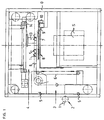
Die hier dargestellten Figuren sind jeweils vereinfachte Darstellungen, wobei die zur Erläuterung jeweils nicht erforderlichen Elemente nicht dargestellt sind, um so die Zeichnung zu entlasten. Entsprechend sind in der Figur 1 alle Elemente weggelassen, die nicht zum Fördern und Gruppieren der Produkteeinheiten erforderlich sind.The figures shown here are each simplified Representations, the explanatory notes are not required elements are not shown, so the Relieve drawing. All are corresponding in FIG. 1 Elements omitted that are not for promotion and grouping of the product units are required.
Die gesamte Vorrichtung ist in einem Chassisrahmen 0
angeordnet, der im wesentlichen den Kanten eines Würfels oder
Kubus' entspricht. Die in Schachteln abzufüllenden
Produkteeinheiten 1 kommen kontinuierlich von einem hier
lediglich schematisch dargestellten Ende einer Produktionslinie
2. Von einer Fördertrommel werden die Produkteeinheiten
1 in Produktegondeln 5 abgegeben, die in einer endlosen Kette
einer Fördereinheit 3 eingegliedert sind. Ueber verschiedene
Umlenkrollen gelangen die Gondeln 5 mit den darin
befindlichen Produkteeinheiten 1 zu einem flexiblen Hilfsträger
6, auf dem die Produkteeinheiten 1 durch eine
entsprechende Kippbewegung der Produktegondeln 5 abgelegt
werden, worauf ein Schlitten 13, der von einem Schrittmotor
14 angetrieben wird, so verschoben wird, dass die
Produkteeinheiten 1 in entsprechende Produkteaufnahmen 7
eines Gruppierträgers 8 fallen. Die Breite des
Gruppierträgers 8 entspricht der Breite der zu füllenden
Schachtel. Der Gruppierträger 8 ist auswechselbar, um den
Grössen der abzufüllenden Produkteeinheiten angepasst zu
werden. Der mittlere Abstand von zwei benachbarten
Produkteaufnahmen 7 entspricht jeweils dem Durchmesser der
zylindrischen Produkteeinheiten 1. Die Breite des Gruppierträgers
8 kann auch breiter als die abzufüllende Schachtel
sein und entsprechend wird die Maschine so gesteuert, dass
nur ein Teil der Produkteaufnahmen 7 gefüllt werden. Sind
alle zu füllenden Produkteaufnahmen 7 gefüllt, schiebt der
Schieber 9 die Produkteeinheiten 1 vom Gruppierträger 8
senkrecht zur Zeichnungsebene weg auf eine Zwischenplatte 11.
Diese ist jedoch nur in der Figur 2 ersichtlich. Der Schieber
9 wird betätigt durch einen Schieberantrieb 10. Diese oder
ähnliche Förder- und Gruppiereinheiten sind bekannt und es
wird diesbezüglich auf die eingangs erwähnten Druckschriften
verwiesen. The entire device is in a
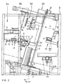
In der Figur 2 ist die Vorrichtung nach Figur 1 um 90°
gedreht dargestellt. Wiederum erkennt man den Chassisrahmen
0, in dem links im Bild die Fördereinheit 3 und die
Gruppiereinheit 4 angeordnet ist. In dieser Ansicht erkennt
man die Schachteleinfülleinheit 20, die noch näher zu
beschreiben ist. Die Schachteleinfülleinheit 20 ist um einen
Winkel α zur Vertikalen geneigt. Die Schachteleinfülleinheit
20 ist oben von der Gruppiereinheit 4 weg geneigt angeordnet.
Zwischen der Gruppiereinheit 4 und der Schachteleinfülleinheit
20 ist eine schwenkbare Zwischenplatte 11 angeordnet.
Der hier nur schematisch erkennbare Schieber 9 schiebt die
Produkteeinheiten 1 vom Gruppierträger 8 auf die Zwischenplatte
11. Die Zwischenplatte 11 ist um eine Schwenkachse 12
verschiebbar. Bei der Uebernahme der gruppierten Einheiten 1
auf die Zwischenplatte 11 befindet sich das von der
Schwenkachse 12 entfernt gelegene Ende etwa fluchtend mit dem
Gruppierträger 8. In dieser Lage ist die Zwischenplatte 11
etwa horizontal oder leicht zum Gruppierträger 8 hin geneigt.
Der Schieber 9 schiebt nun die gruppierten Einheiten 1 auf
die Zwischenplatte 11. Da dies relativ schnell erfolgt, muss
sichergestellt werden, dass die Produkteeinheiten 1 nicht
bereits in dieser Lage der Zwischenplatte 11 über diese
hinweg rutschen. Hierzu kann die Zwischenplatte 11 mit einer
Schicht versehen sein, die einen höheren Reibungskoeffizienten
hat. Zudem kann die Zwischenplatte bezüglich
der Horizontale um einen Winkel β geneigt sein, so dass die
Produkteeinheiten auf die Zwischenplatte aufwärts geschoben
werden müssen. Dieser Winkel β kann beispielsweise
einstellbar sein. Entsprechend ist die Neigung der
Zwischenplatte in der beschriebenen Lage zum Gruppierträger 8
in einem Winkel zwischen 0° und 15° verstellbar, vorzugsweise
jedoch zwischen 2° und 15°.In Figure 2, the device of Figure 1 is 90 °
shown rotated. Again you can see the
Liegen die Produkteeinheiten auf der schwenkbaren Zwischenplatte
11, so schwenkt diese um die genannte Schwenkachse 12
in eine Neigung, welche der Neigung der Schachtel entspricht.
In dieser Lage rutschen die Produkteeinheiten in der
gruppierten Form von der Zwischenplatte 11 in die bereitstehende
Schachtel S. Hilfsweise kann zusätzlich ein
Einführschieber 14 vorhanden sein, der hier rein schematisch
in seinen beiden Endlagen dargestellt ist. Befindet sich die
Produktegruppe 15 in der Schachtel S, schwenkt die
Zwischenplatte 11 wiederum in die Lage zurück, in der sie
eine neue Produktegruppe aufnehmen kann. Gleichzeitig wird
die Schachtel S um den Durchmesser der einzufüllenden
Produkteeinheiten abgesenkt. Auf diese Weise wird die gesamte
Schachtel gefüllt und anschliessend in die Tieflage S'
abgesenkt. Hierbei wird sie durch eine verschiebbare Stütze
61 geführt. Die verschiebbare Stütze 61 ist auf einer Schiene
63 angeordnet, die senkrecht zur Schachteleinfülleinheit 20
verläuft und somit um den Winkel α zur Horizontalen geneigt
ist. Die verschiebbare Stütze 61 wird anschliessend nach
unten weggefahren und die gefüllte Schachtel wird vom
schwenkbaren Auflagetisch 60 aufgenommen und anschliessend
wegtransportiert.The product units lie on the swiveling
Für die Zuführung der zu füllenden Schachteln ist eine
Schachtelzuführung 40 vorgesehen. Auch die Schachtelzuführung
40 ist vorteilhafterweise um den Winkel α geneigt
angeordnet. Die Schachtelzuführung 40 wird durch zwei
senkrecht zueinander stehende Rollenbahnen 41 gebildet.
Oberhalb der Schachtelzuführung 40 verläuft eine weitere
Schiene 56 parallel zur zuvor beschriebenen Schiene 63, also
wiederum um den Winkel α zur Horizontalen geneigt. Auf
dieser Schiene 56 ist ein Schachtelgreifer 50 verschiebbar
angeordnet. Der Schachtelgreifer 50 hat Sauger 51, die an
entsprechenden Saugarmen 52 angeordnet sind. Der Schachtelgreifer
40 kann zwischen den beiden noch zu beschreibenden
verschiebbaren Holmen hindurch eine auf der Schachtelzuführung
40 bereitstehende Schachtel ergreifen und dank dem
drehbaren Schwenkarm 52 von einer liegenden Position in eine
stehende Position schwenken. Mit derselben Rotationsachse 57,
um welche der Schwenkarm 52 drehbar ist, ist ein weiterer
Schwenkarm 55 drehbar. Auf diesem Schwenkarm 55 sind
endständig Rollen 54 angeordnet. Die Rollen 54 mit dem
Schwenkarm 55 bilden zusammen den Schachtelöffner 53. Während
die Schachtel S mittels den Saugern 51 gehalten ist, dreht
der Schwenkarm 55 und die Rollen 54 entsprechend an den
Innenwänden der Seitenwände der Schachtel S und drücken diese
in die vollständig offene Position. Entsprechend ist der
Abstand zwischen den Rollen 54 gleich der Breite der zu
öffnenden Schachtel. Entsprechend dem Pfeil P wird die
Schachtel von der Schachtelzuführung 40 nach vorne bewegt und
auf entsprechenden Stützplatten 29 abgestellt und mittels
noch zu beschreibenden Klammern gehalten.There is one for feeding the boxes to be filled
Die Schachteleinfülleinheit 20 besteht im wesentlichen aus
zwei parallelen oben und unten verlaufenden Schienen 21 und
zwei gegenläufig darauf beweglichen, verschiebbaren Holmen
22. Die Schienen 21 und die verschiebbaren Holme 22 bilden so
ein verstellbares Viereck 23. Die Breite dieses Viereckes ist
anpassbar an die Breite der zu füllenden Schachtel S. Das
gesamte verstellbare Viereck 23 definiert somit die Neigung
α der Einfülleinheit 20. Zur Verstellung der Holme 22 ist
eine Spindel 24 vorgesehen, die mittig gelagert ist und zwei
Spindelabschnitte mit gegenläufigen Gewindeabschnitten
aufweist. Auf jedem Spindelabschnitt 25 lagert ein
verstellbarer Holm 22. Wird die Spindel 24 in der einen
Richtung gedreht, so bewegen sich die beiden Holme 22
gleichmässig voneinander weg, wird die Spindel 24 in die
andere Richtung gedreht, nähern sich die beiden
verschiebbaren Holme 22. Diese Einstellung muss nur erfolgen
bei der Einrichtung der Vorrichtung, wenn diese auf eine
bestimmte Schachtelgrösse eingestellt wird. Deutlich erkennt
man zwischen den beiden verschiebbaren Holmen 22 den mittig
dazu angeordneten Schachtelgreifer 50. Auf jedem
verschiebbaren Holm 22 ist eine Gliederkette 28 um obere und
untere Umlenkrollen geführt. An dieser Gliederkette 28 sind
an jedem Kettenglied je eine Klammer 30 oder Stützplatten 29
angeordnet. Die Stützplatten 29 verlaufen bezogen auf den
Zwischenraum zwischen den beiden Holmen 22 nach aussen
gerichtet nach oben und im Zwischenraum in diesen
hineinragend nach unten. Während die Stützplatten 29 nach
unten laufen, liegen auf denselben die zu füllenden
Schachteln S auf. Gleichzeitig werden die Schachtelränder von
den noch zu beschreibenden Klammern 30 entlang den
Längskanten gehalten. An jedem Holm 22 ist zumindest oben ein
Klammeröffner 37 fest angeordnet. Dieser Klammeröffner 37 ist
mit einer auswechselbaren Betätigungsplatte 38 ausgerüstet.
Diese auswechselbaren Betätigungplatten 38 werden
entsprechend der Grösse der zu haltenden Schachteln montiert.The
Der Schachtelgreifer 50 fährt somit auf der Schiene 56 in
Richtung zur Schachtelzuführung 40, wo die Sauger 51 die
Schachtel greifen, diese um 90° drehen, falls erforderlich,
und zwischen den beiden Holmen 22 nach vorne bewegen, wobei
der Schachtelgreifer 50 auf der Schiene 56 wieder nach vorne
fährt. Während die Schachtel durch die Sauger 51 gehalten
wird, dreht der Schwenkarm 55 und die Rollen 54 drücken die
Seitenwände der Schachtel in die exakt senkrechte Lage. Die
Betätigungsplatte 38 drückt hierbei auf das umgebogene Ende
34' der Klammerplatte 34, wobei die Druckfeder 36
zusammengedrückt und elastisch verformt wird, während
gleichzeitig die Klammerplatte 34 sich um die Schwenkachse 35
bewegt. Die ansonsten an der Schachtelführungsplatte 33
anliegende Klammerplatte 34 bewegt sich dabei von derselben
weg und gibt einen Raum frei, in den die seitliche
Schachtelwand hineinfährt. Diese Position ist in der Figur 4
in der unteren Hälfte dargestellt. In der Figur 4 oben ist
eine unbetätigte Klammer, die an der Aussenseite des Holmes
22 nach oben läuft, ersichtlich. Ist die Schachtel
eingefahren, so wird der Druck auf die auswechselbare
Betätigungsplatte 38 des Klammeröffners 37 entfernt und die
Klammerplatte 34 drückt den Schachtelrand an die
Schachtelführungsplatte 33. Auf diese Weise ist nicht nur die
Schachtel gehalten, sondern es ist auch gewährleistet, dass
der Schachtelrand exakt gerade verlaufend ist, so dass nicht
durch Verformungen das Einfüllen der Produkteeinheiten
behindert wird. Die gehaltene Position ist in der Figur 5
oben dargestellt, während unten wiederum die unbetätigte
aussen am Holm nach oben laufende Klammer dargestellt ist. In
der Figur 5 sind die Teile der Kettengliederkonstruktion
weggelassen. Hierdurch wird deutlicher, dass der Klammeröffner
37 als eine Art Wippekonstruktion direkt auf dem Holm
22 befestigt angeordnet ist.The
Obwohl die hier beschriebene Vorrichtung besonders für Produkteeinheiten mit kleinen Durchmessern konzipiert ist, kann sie selbstverständlich auch für Produkteeinheiten mit grösseren Durchmessern verwendet werden. Hiermit soll jedoch lediglich zum Ausdruck gebracht werden, dass die erfindungsgemässe Vorrichtung vom Käufer ohne weiteres auch für Produkteeinheiten grösseren Durchmessers verwendet werden kann. Trotzdem ist selbstverständlich, dass für grössere Produkteeinheiten, wie Haushaltpapierrollen oder dergleichen, selbstverständlich sehr viel einfachere und preisgünstigere Vorrichtungen verwendet werden können. Although the device described here is particularly suitable for Product units with small diameters is designed, can of course also be used for product units larger diameters can be used. Hereby, however only to be expressed that the Device according to the invention by the buyer without further ado can be used for product units of larger diameter can. Nevertheless, it goes without saying that for larger ones Product units, such as household paper rolls or the like, of course, much simpler and cheaper Devices can be used.
- 00
- Chassisrahmenchassis frame
- 11
- Produkteeinheitproducts unit
- 22
- Produktionslinieproduction line
- 33
- Fördereinheitdelivery unit
- 44
- Gruppiereinheitgrouping
- 55
- Produktegondelnproducts gondolas
- 66
- flexibler Hilfsträgerflexible subcarrier
- 77
- Produkteaufnahmeproducts recording
- 88th
- GruppierträgerGruppierträger
- 99
- Schieberpusher
- 1010
- Schieberantriebslide drive
- 1111
- Zwischenplatteintermediate plate
- 1212
- Schwenkachseswivel axis
- 1313
- Schlittencarriage
- 1414
- Einführschieberinsertion slider
- 2020
- Schachteleinfülleinheitbox filling
- 2121
- Schienenrails
- 2222
- verschiebbare Holmesliding bars
- 2323
- verstellbares Viereckadjustable square
- 2424
- Spindelspindle
- 2525
- Spindelabschnitte mit gegenläufigen GewindeabschnittenSpindle sections with opposite thread sections
- 2626
- mechanische Kopplung des Antriebesmechanical coupling of the drive
- 2727
- Antriebsmotor (Schrittmotor)Drive motor (stepper motor)
- 2828
- Gliederkettenlink chains
- 2929
- Stützplattensupport plates
- 3030
- Klammern clinch
- 3131
- Kettengliedlink
- 3232
- KettengliedrollenChain link rollers
- 3333
- SchachtelführungsplatteBox guide plate
- 3434
- Klammerplattebracket plate
- 3535
- Schwenkachseswivel axis
- 3636
- Druckfedercompression spring
- 3737
- KlammeröffnerKlammeröffner
- 3838
- auswechselbare Betätigungsplatteinterchangeable actuator plate
- 3939
- Schwenkachseswivel axis
- 4040
- Schachtelzuführungbox supply
- 4141
- Rollenbahnroller conveyor
- 5050
- Schachtelgreiferbox gripper
- 5151
- SaugerMammal
- 5252
- Schwenkarmswivel arm
- 5353
- SchachtelöffnerSchachtelöffner
- 5454
- Rollenroll
- 5555
- Schwenkarmswivel arm
- 5656
- Schienerail
- 6060
- Ablagetischtray table
- 6161
- verschiebbare Stützesliding support
- 6262
- Schwenkachseswivel axis
- 6363
- Schienerail
- SS
- Schachtelbox
Claims (15)
- A device for transferring elongate, at least approximately cylindrical production units (1), preferably tubes, sleeves or cans which arrive continuously from a production line (2), and which by way of a grouping unit (4) for forming product groups (15) with a preselectable unit number are deposited from a continuously supplying conveyor unit (3) into a grouping carrier (8) with product receivers (7) which accommodates the product groups and from which the product groups (15) may be filled into a box (S) by way of a box filling unit (20), characterised in that the box filling unit (20) is inclined away from the grouping unit (4) deviating by an angle of 5° to 30° from the vertical, and between the grouping unit (4) and the box filling unit (20) there is arranged an intermediate plate (11) which is pivotable about a horizontal axis and onto which a product group (15) may be pushed and by way of which in the condition pivoted downwards, the product groups (15) may be filled from the group carrier (8) into the box (S).
- A device according to claim 1, characterised in that the box filling unit (20) consists of two parallel rails (21) on which two parallel spars (22) displaceable in opposite directions to one another are guided, wherein the rails (21) and the two spars (22) form a rectangle (23) which may be adjusted in width and which defines the inclination (a) of the filling unit.
- A device according to claim 2, characterised in that on the parallel displaceable spars (22) there are present at least means for holding (29, 30) and the stepwise movable guiding (28) of the boxes (S) to be filled, in the longitudinal direction of the spars (22).
- A device according to claim 2, characterised in that on each spar (22) there is arranged a revolving link chain (28) on which support plates (29) are fastened at a regular distance which are counter to one another and are on an equal level and serve as support surfaces of the boxes to be filled.
- A device according to claim 2, characterised in that the two parallel spars (22) at the top and bottom are movable on the two rails (21) by way of driven and electrically or mechanically coupled (26) synchronously running spindles (24, 25).
- A device according to claim 4, characterised in that link chains (28) are equipped with spring-loaded clips (30) by way of which the boxes (S) to be filled are held along the side edges.
- A device according to claim 2, characterised in that the box filling unit (20) comprises a box feed (40) by way of which the boxes to be filled may be led into the region between the two movable spars (22), and to behind the adjustable rectangle (23) with respect to the filling direction of the boxes.
- A device according to claim 7, characterised in that the box feed (40) consists of a roller path (41) or transport on which the boxes (S) may be fed according to the inclination (α) of the adjustable rectangle (23).
- A device according to claim 1, characterised in that the pivotable intermediate plate (11) may be pivoted at least from the horizontal direction into the inclined direction (α) of the box filling unit (20).
- A device according to claim 9, characterised in that the pivotable intermediate plate (11) in the position in which the grouped product units (1) are transported from the group carrier (8) onto the intermediate plate is inclined (β) towards the group carrier (8).
- A device according to claim 10, characterised in that the inclination (ß) towards the group carrier may be adjusted between 2° and 15°.
- A device according to claim 1, characterised in that the grouping unit comprises a slider (9) by way of which the grouped product units (1) may be pushed from the grouping carrier (8) onto the intermediate plate (11).
- A device according to claim 1 and 8, characterised in that a box gripper (50) is arranged centrally between the two displaceable spars (22) which is movably mounted on the rail (56) perpendicular to the inclination (α) of the filling unit (20) and permits the boxes (S) to be filled to be transported from the box feed (40) to the box filling unit (20).
- A device according to claim 13, characterised in that the box gripper (50) is equipped with a box opener (53).
- A device according to the claims 13 and 14, characterised in that the box gripper (50) and the box opener (53) are designed rotatable about the same axis, but independently of one another.
Applications Claiming Priority (2)
| Application Number | Priority Date | Filing Date | Title |
|---|---|---|---|
| CH2492000 | 2000-02-08 | ||
| CH2492000 | 2000-02-08 |
Publications (2)
| Publication Number | Publication Date |
|---|---|
| EP1123867A1 EP1123867A1 (en) | 2001-08-16 |
| EP1123867B1 true EP1123867B1 (en) | 2004-06-30 |
Family
ID=4467387
Family Applications (1)
| Application Number | Title | Priority Date | Filing Date |
|---|---|---|---|
| EP00811205A Expired - Lifetime EP1123867B1 (en) | 2000-02-08 | 2000-12-19 | Machine for packaging tubes |
Country Status (3)
| Country | Link |
|---|---|
| EP (1) | EP1123867B1 (en) |
| AT (1) | ATE270223T1 (en) |
| DE (1) | DE50006952D1 (en) |
Families Citing this family (1)
| Publication number | Priority date | Publication date | Assignee | Title |
|---|---|---|---|---|
| DE10316853B4 (en) * | 2003-04-11 | 2007-10-31 | Aisa Automation Industrielle S.A. | Device for automatic packaging of containers |
Citations (2)
| Publication number | Priority date | Publication date | Assignee | Title |
|---|---|---|---|---|
| EP0438974A1 (en) * | 1990-01-25 | 1991-07-31 | Pamag Ag | Method for packaging sleeves or tubes in boxes, and machine for executing the method |
| EP0594917A1 (en) * | 1991-04-04 | 1994-05-04 | Pamag Ag | Method for taking over continuously delivered products from a production device and for delivering discontinuously a number of those products in a delivering station |
Family Cites Families (6)
| Publication number | Priority date | Publication date | Assignee | Title |
|---|---|---|---|---|
| DE2200390A1 (en) * | 1972-01-05 | 1973-07-12 | Loesch Gmbh Maschf | DEVICE FOR TRANSFERRING OBJECTS IN COLLECTIVE PACKS |
| IT1193403B (en) * | 1980-01-14 | 1988-06-22 | Meccanotecnica Spa | BOOK STACKING MACHINE |
| US4291519A (en) * | 1980-05-30 | 1981-09-29 | Daniel Johnson | Bottle carton filling machine |
| NL8802075A (en) * | 1988-08-22 | 1990-03-16 | Breda Packaging Bv | METHOD AND APPARATUS FOR ARRANGING ARTICLES IN A HOLDER |
| DE4241440A1 (en) * | 1992-09-02 | 1994-03-10 | Ostma Maschinenbau Gmbh | Method and device for introducing product-filled packaging, in particular tubular bags, into shipping containers |
| US5732536A (en) * | 1996-10-28 | 1998-03-31 | Industrial Technology Research Institute | Tape roll in-series package machine |
-
2000
- 2000-12-19 EP EP00811205A patent/EP1123867B1/en not_active Expired - Lifetime
- 2000-12-19 AT AT00811205T patent/ATE270223T1/en not_active IP Right Cessation
- 2000-12-19 DE DE50006952T patent/DE50006952D1/en not_active Expired - Lifetime
Patent Citations (2)
| Publication number | Priority date | Publication date | Assignee | Title |
|---|---|---|---|---|
| EP0438974A1 (en) * | 1990-01-25 | 1991-07-31 | Pamag Ag | Method for packaging sleeves or tubes in boxes, and machine for executing the method |
| EP0594917A1 (en) * | 1991-04-04 | 1994-05-04 | Pamag Ag | Method for taking over continuously delivered products from a production device and for delivering discontinuously a number of those products in a delivering station |
Also Published As
| Publication number | Publication date |
|---|---|
| ATE270223T1 (en) | 2004-07-15 |
| DE50006952D1 (en) | 2004-08-05 |
| EP1123867A1 (en) | 2001-08-16 |
Similar Documents
| Publication | Publication Date | Title |
|---|---|---|
| DE4100769C2 (en) | Device for conveying products in a packaging machine | |
| DE3784691T2 (en) | Machine for filling containers with rod-shaped objects. | |
| EP0372314B1 (en) | Device for turning over a package | |
| DE2020825B2 (en) | Automatic device for feeding cigarettes or the like. rod-shaped objects | |
| DE3829931A1 (en) | RAIL FEEDER | |
| DE69104553T2 (en) | Device for producing cartons from flat, sleeve-like blanks. | |
| DE4141830C2 (en) | Stacking and packaging device for individual pieces | |
| DE2635194A1 (en) | FEED DEVICE FOR GOODS TO BE PRINTED | |
| DE4013066C2 (en) | Bobbin changing device | |
| EP0059984A2 (en) | Distributing device for a conveyor | |
| DE3153367C2 (en) | ||
| CH454010A (en) | Device for placing pieces of confectionery aligned on a feed device into packaging | |
| DE4329179A1 (en) | Machine for transferring articles into a packaging unit | |
| EP1020359A2 (en) | Device for transporting objects and simultaneously turning them, especially folding boxes | |
| DE102015113650B4 (en) | Device for attaching valve bags and method for operating | |
| DE4008592A1 (en) | Device for the automatic feeding and removal of boards made of carton board, corrugated board and the like to a stamping and/or printing machine | |
| DE2842432C2 (en) | Device for the orderly depositing of cross-wound bobbins | |
| EP1123867B1 (en) | Machine for packaging tubes | |
| DE2440106A1 (en) | DEVICE FOR APPLYING ADHESIVE | |
| CH649746A5 (en) | RETURNING MACHINE. | |
| DE4406089C2 (en) | Device for filling tablets or the like into tablet tubes | |
| EP0836995A1 (en) | Method and device for packaging cans or tubes | |
| DE3815557A1 (en) | Composite machine for the automatic packaging in folding boxes of material to be packaged | |
| DE19614807C2 (en) | Device for applying packages in a turned or unturned form to a subsequent device | |
| DE19534954A1 (en) | High storage unit for workpieces, especially flat pieces of furniture |
Legal Events
| Date | Code | Title | Description |
|---|---|---|---|
| PUAI | Public reference made under article 153(3) epc to a published international application that has entered the european phase |
Free format text: ORIGINAL CODE: 0009012 |
|
| AK | Designated contracting states |
Kind code of ref document: A1 Designated state(s): AT BE CH CY DE DK ES FI FR GB GR IE IT LI LU MC NL PT SE TR |
|
| AX | Request for extension of the european patent |
Free format text: AL;LT;LV;MK;RO;SI |
|
| AKX | Designation fees paid |
Free format text: AT BE CH CY DE DK ES FI FR GB GR IE IT LI LU MC NL PT SE TR |
|
| 17P | Request for examination filed |
Effective date: 20011001 |
|
| GRAP | Despatch of communication of intention to grant a patent |
Free format text: ORIGINAL CODE: EPIDOSNIGR1 |
|
| GRAP | Despatch of communication of intention to grant a patent |
Free format text: ORIGINAL CODE: EPIDOSNIGR1 |
|
| GRAS | Grant fee paid |
Free format text: ORIGINAL CODE: EPIDOSNIGR3 |
|
| GRAA | (expected) grant |
Free format text: ORIGINAL CODE: 0009210 |
|
| AK | Designated contracting states |
Kind code of ref document: B1 Designated state(s): AT BE CH CY DE DK ES FI FR GB GR IE IT LI LU MC NL PT SE TR |
|
| PG25 | Lapsed in a contracting state [announced via postgrant information from national office to epo] |
Ref country code: IE Free format text: LAPSE BECAUSE OF FAILURE TO SUBMIT A TRANSLATION OF THE DESCRIPTION OR TO PAY THE FEE WITHIN THE PRESCRIBED TIME-LIMIT Effective date: 20040630 Ref country code: CY Free format text: LAPSE BECAUSE OF FAILURE TO SUBMIT A TRANSLATION OF THE DESCRIPTION OR TO PAY THE FEE WITHIN THE PRESCRIBED TIME-LIMIT Effective date: 20040630 Ref country code: FI Free format text: LAPSE BECAUSE OF FAILURE TO SUBMIT A TRANSLATION OF THE DESCRIPTION OR TO PAY THE FEE WITHIN THE PRESCRIBED TIME-LIMIT Effective date: 20040630 Ref country code: NL Free format text: LAPSE BECAUSE OF FAILURE TO SUBMIT A TRANSLATION OF THE DESCRIPTION OR TO PAY THE FEE WITHIN THE PRESCRIBED TIME-LIMIT Effective date: 20040630 Ref country code: TR Free format text: LAPSE BECAUSE OF FAILURE TO SUBMIT A TRANSLATION OF THE DESCRIPTION OR TO PAY THE FEE WITHIN THE PRESCRIBED TIME-LIMIT Effective date: 20040630 |
|
| REG | Reference to a national code |
Ref country code: GB Ref legal event code: FG4D Free format text: NOT ENGLISH Ref country code: CH Ref legal event code: NV Representative=s name: PATENTANWAELTE FELDMANN & PARTNER AG Ref country code: CH Ref legal event code: EP |
|
| GBT | Gb: translation of ep patent filed (gb section 77(6)(a)/1977) |
Effective date: 20040630 |
|
| REG | Reference to a national code |
Ref country code: IE Ref legal event code: FG4D Free format text: GERMAN |
|
| REF | Corresponds to: |
Ref document number: 50006952 Country of ref document: DE Date of ref document: 20040805 Kind code of ref document: P |
|
| PG25 | Lapsed in a contracting state [announced via postgrant information from national office to epo] |
Ref country code: GR Free format text: LAPSE BECAUSE OF FAILURE TO SUBMIT A TRANSLATION OF THE DESCRIPTION OR TO PAY THE FEE WITHIN THE PRESCRIBED TIME-LIMIT Effective date: 20040930 Ref country code: DK Free format text: LAPSE BECAUSE OF FAILURE TO SUBMIT A TRANSLATION OF THE DESCRIPTION OR TO PAY THE FEE WITHIN THE PRESCRIBED TIME-LIMIT Effective date: 20040930 Ref country code: SE Free format text: LAPSE BECAUSE OF FAILURE TO SUBMIT A TRANSLATION OF THE DESCRIPTION OR TO PAY THE FEE WITHIN THE PRESCRIBED TIME-LIMIT Effective date: 20040930 |
|
| PG25 | Lapsed in a contracting state [announced via postgrant information from national office to epo] |
Ref country code: ES Free format text: LAPSE BECAUSE OF FAILURE TO SUBMIT A TRANSLATION OF THE DESCRIPTION OR TO PAY THE FEE WITHIN THE PRESCRIBED TIME-LIMIT Effective date: 20041011 |
|
| PG25 | Lapsed in a contracting state [announced via postgrant information from national office to epo] |
Ref country code: LU Free format text: LAPSE BECAUSE OF NON-PAYMENT OF DUE FEES Effective date: 20041219 Ref country code: AT Free format text: LAPSE BECAUSE OF NON-PAYMENT OF DUE FEES Effective date: 20041219 |
|
| PG25 | Lapsed in a contracting state [announced via postgrant information from national office to epo] |
Ref country code: BE Free format text: LAPSE BECAUSE OF NON-PAYMENT OF DUE FEES Effective date: 20041231 Ref country code: MC Free format text: LAPSE BECAUSE OF NON-PAYMENT OF DUE FEES Effective date: 20041231 |
|
| NLV1 | Nl: lapsed or annulled due to failure to fulfill the requirements of art. 29p and 29m of the patents act | ||
| REG | Reference to a national code |
Ref country code: IE Ref legal event code: FD4D |
|
| ET | Fr: translation filed | ||
| PLBE | No opposition filed within time limit |
Free format text: ORIGINAL CODE: 0009261 |
|
| STAA | Information on the status of an ep patent application or granted ep patent |
Free format text: STATUS: NO OPPOSITION FILED WITHIN TIME LIMIT |
|
| 26N | No opposition filed |
Effective date: 20050331 |
|
| BERE | Be: lapsed |
Owner name: *TEXA A.G. Effective date: 20041231 |
|
| PGFP | Annual fee paid to national office [announced via postgrant information from national office to epo] |
Ref country code: FR Payment date: 20051219 Year of fee payment: 6 |
|
| PGFP | Annual fee paid to national office [announced via postgrant information from national office to epo] |
Ref country code: GB Payment date: 20051222 Year of fee payment: 6 |
|
| PGFP | Annual fee paid to national office [announced via postgrant information from national office to epo] |
Ref country code: CH Payment date: 20060327 Year of fee payment: 6 |
|
| PG25 | Lapsed in a contracting state [announced via postgrant information from national office to epo] |
Ref country code: CH Free format text: LAPSE BECAUSE OF NON-PAYMENT OF DUE FEES Effective date: 20061231 Ref country code: LI Free format text: LAPSE BECAUSE OF NON-PAYMENT OF DUE FEES Effective date: 20061231 |
|
| PGFP | Annual fee paid to national office [announced via postgrant information from national office to epo] |
Ref country code: IT Payment date: 20061231 Year of fee payment: 7 |
|
| REG | Reference to a national code |
Ref country code: CH Ref legal event code: PL |
|
| GBPC | Gb: european patent ceased through non-payment of renewal fee |
Effective date: 20061219 |
|
| REG | Reference to a national code |
Ref country code: FR Ref legal event code: ST Effective date: 20070831 |
|
| PG25 | Lapsed in a contracting state [announced via postgrant information from national office to epo] |
Ref country code: GB Free format text: LAPSE BECAUSE OF NON-PAYMENT OF DUE FEES Effective date: 20061219 |
|
| BERE | Be: lapsed |
Owner name: *TEXA A.G. Effective date: 20041231 |
|
| PG25 | Lapsed in a contracting state [announced via postgrant information from national office to epo] |
Ref country code: PT Free format text: LAPSE BECAUSE OF NON-PAYMENT OF DUE FEES Effective date: 20041130 |
|
| PG25 | Lapsed in a contracting state [announced via postgrant information from national office to epo] |
Ref country code: FR Free format text: LAPSE BECAUSE OF NON-PAYMENT OF DUE FEES Effective date: 20070102 |
|
| PG25 | Lapsed in a contracting state [announced via postgrant information from national office to epo] |
Ref country code: IT Free format text: LAPSE BECAUSE OF NON-PAYMENT OF DUE FEES Effective date: 20071219 |
|
| REG | Reference to a national code |
Ref country code: DE Ref legal event code: R082 Ref document number: 50006952 Country of ref document: DE Representative=s name: KEILITZ & SOELLNER, PARTNERSCHAFT, DE Ref country code: DE Ref legal event code: R082 Ref document number: 50006952 Country of ref document: DE Representative=s name: PATENTANWAELTE BEHRMANN WAGNER PARTNERSCHAFTSG, DE |
|
| REG | Reference to a national code |
Ref country code: DE Ref legal event code: R082 Ref document number: 50006952 Country of ref document: DE Representative=s name: PATENTANWAELTE BEHRMANN WAGNER PARTNERSCHAFTSG, DE |
|
| PGFP | Annual fee paid to national office [announced via postgrant information from national office to epo] |
Ref country code: DE Payment date: 20200127 Year of fee payment: 20 |
|
| REG | Reference to a national code |
Ref country code: DE Ref legal event code: R071 Ref document number: 50006952 Country of ref document: DE |