EP0836995A1 - Method and device for packaging cans or tubes - Google Patents
Method and device for packaging cans or tubes Download PDFInfo
- Publication number
- EP0836995A1 EP0836995A1 EP97810599A EP97810599A EP0836995A1 EP 0836995 A1 EP0836995 A1 EP 0836995A1 EP 97810599 A EP97810599 A EP 97810599A EP 97810599 A EP97810599 A EP 97810599A EP 0836995 A1 EP0836995 A1 EP 0836995A1
- Authority
- EP
- European Patent Office
- Prior art keywords
- box
- packaging
- cans
- tubes
- packing
- Prior art date
- Legal status (The legal status is an assumption and is not a legal conclusion. Google has not performed a legal analysis and makes no representation as to the accuracy of the status listed.)
- Withdrawn
Links
Images


Classifications
-
- B—PERFORMING OPERATIONS; TRANSPORTING
- B65—CONVEYING; PACKING; STORING; HANDLING THIN OR FILAMENTARY MATERIAL
- B65B—MACHINES, APPARATUS OR DEVICES FOR, OR METHODS OF, PACKAGING ARTICLES OR MATERIALS; UNPACKING
- B65B19/00—Packaging rod-shaped or tubular articles susceptible to damage by abrasion or pressure, e.g. cigarettes, cigars, macaroni, spaghetti, drinking straws or welding electrodes
- B65B19/34—Packaging other rod-shaped articles, e.g. sausages, macaroni, spaghetti, drinking straws, welding electrodes
Definitions
- the present invention relates to a method for packaging of cans or tubes according to the preamble of the claim 1. It also relates to a packaging machine for performing the Method according to the preamble of claim 7.
- the method according to the invention uses a packaging machine with interchangeable packaging module, which in one embodiment for strapping the cans or tubes and in one another embodiment for packing the cans or tubes in Boxes can be used.
- a packaging machine with interchangeable packaging module which in one embodiment for strapping the cans or tubes and in one another embodiment for packing the cans or tubes in Boxes can be used.
- the packaging module can be strapped to the type of packaging the type of packaging, filling in boxes, and vice versa, be converted without extensive and thus time-consuming Modifications to the machine must be made or even the entire packaging machine has to be replaced.
- This is made possible in particular by the fact that the box feeder to the side, i.e. perpendicular to the filling direction the cans or tubes into the box.
- the packaging gauges and suction pads both for strapping and for box filling use.
- the packaging module can be very narrow train because the minimum width by the depth of the filling box is limited.
- a brief interruption is sufficient when changing the type of packaging the packaging machine during which the packaging module is replaced becomes.
- the packaging gauge and the suction pad made and the control program is changed.
- all components of the packaging machine can be used for both types of packaging a packaging machine for the price of the interchangeable module, which in Ratio to the cost of such a machine is small to be expanded by a packaging function.
- the construction of the box filling module enables it under Utilization of the modular structure that all for filling one Box of necessary cans or tubes in one step and in a desired tight packing in the box will.
- Another advantage is that the packaging modules are on used different machines and exchanged between machines can be.
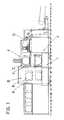
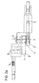
- FIGS. 1, 2a and 2b show the schematic structure of the Packing machine according to the invention can be seen.
- a conveyor station F is a layer of cans D by means of a slide not shown here in a gradually lowerable Packing gauge 2 pushed.
- the shape of the packaging gauge 2 corresponds to the shape to be achieved Packaging. If the cans D are to be strapped with a strap, the packaging gauge preferably has a hexagonal Form as indicated in the figure with the reference number 2 ' is. If the cans D are packed in boxes, corresponds to the packing gauge 2 of the opening of the box and is, as can be seen in FIG. 2a, preferably rectangular.
- the packaging gauge 2 becomes the conveyor station F to the packaging station V driven. In this example, it becomes this lowered.
- the cans D together in the form of a tight packing from the packaging theory 2 removed to them with common packaging Mistake. Further transport takes place using a suction pad 3, which has a flat suction surface, the is aligned parallel to the packaging apprenticeship.
- the suction pad 3 is in the direction of the can delivery from the packaging gauge 2, the filling direction, movable and has a front End position at the packaging location and a rear end position on which the packaged cans D on a perpendicular to Filling direction slidable transport plate get where they are held by a press arm pressing from above and with this transport plate to a next processing station B are passed on.
- the type of packaging can be selected between box filling and strapping.
- One packaging module each can be inserted into a designated bay of the packaging machine, more precisely between the lowered packaging jig 2 and the suction gripper 3, and precisely positioned and locked using adjusting rollers or rails.
- Each packaging module consists of a basal body on which either a box or a tape feeder is arranged.
- the packaging material i.e. the box or the band, is brought to the packaging station in a plane, the feed plane, which is perpendicular to the direction in which the cans D are dispensed from the packaging gauge, the filling direction.
- the packaging gauge 2 and the suction pad 3 are required for both types of packaging. They can therefore be identical or, depending on the shape of the desired packaging, can also be replaced when changing the packaging module. However, it is essential that the same holders and displacement mechanisms are used for all types of packaging gauges or suction cups.
- the packaging module a strapping or a box filling module.
- the strapping module consists of known elements and is therefore not shown in detail here. On the strapping module there is a roll of tape and means for strapping. The remaining elements described here are part of the stationary packaging machine.
- the lowered, with cans D filled packing gauge is opened in the horizontal direction the strapping module steered and the strap around the cans D looped, cut and the ends welded.
- a Suction cup with several suction openings is on the packaging gauge opposite side to the cans D, whereby he draws the cans D with negative pressure.
- the Can D aligned so that the can bottoms become a suction cup are executed. At the same time or afterwards it will now empty packaging gauge moved back horizontally and again raised to conveyor station F.
- the suction pad is in the loading direction drove back from the place of packaging and leads the strapped cans D with. Arrived in the rear end position the strapped can package 9 on the perpendicular to the loading direction slidable transport plate, is with a from above on the Strapping package pressing arm pressed and with this transport plate passed on to the processing station.
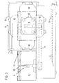
- the box filling module 1 is shown in FIGS. 3, 4a and 4b shown.
- the box filling module 1 has a vertical standing box carrier 5, which in the feed plane from an outer end position to an inner one, the packaging theory adjacent end position is movable.
- the box carrier 5 by a carriage formed, which by means of a linear cylinder 11 in a horizontal Direction along a slot 12 in the box filling module 1 can be moved back and forth.
- the box carrier a swivel arm, which in the Feed level is pivotable.
- the box carrier 5 has a support arm 50 and at least one, here three, adjustable booms 51 arranged thereon on. It is best seen in Figure 3.
- One too filling, open box 8 is in the side position in the outer end position placed on the box carrier 5.
- This is thanks to the adjustable bracket 51 on the Box size adjustable.
- Support arm and boom are designed that with the box attached, the box bottom on the side facing away from the packaging gauge. The opening of the box is thus on the side. If if the box carrier moves horizontally, the box becomes according to the orientation of the packaging gauge on the Box carrier turned up. In the case of the swiveling box carrier the box is arranged rotated by 90 °.
- the box carrier 5 moves with the box 8 to the packaging station between the lowered packaging gauge 2 and the suction gripper 3 to its inner end position, which is shown in FIG. 4a with broken lines.
- the box 8 is taken over by the suction gripper 3, the suction gripper 3 being simultaneously or subsequently pushed horizontally in the direction of the lowered packaging gauge until it touches the bottom 80 of the box 8. He sucks on the box bottom 80 and moves the box away from the box carrier 5.
- the suction gripper 3 has a square suction plate with at least four suction cups 30, which are arranged in the corners of the suction plate.
- the box carrier 5 is now moved at least until it completely clears the opening of the box. It is preferably moved back to its outer end position in order to accommodate a new box.
- the suction gripper 3, on the other hand travels with the box 8 to the lowered packaging jig 2, as shown in broken lines in FIG.
- the box becomes here preferably taken up by a box holder 6.
- This box holder 6 is stationary on the box filling module 1 arranged and consists of a box holder frame 60 and several, here four, displaceable clamping elements 61.
- the box holder 6 is used to fix the side walls of the Box while filling.
- the clamping elements 61 have for this each have an inclined plate, which in the Protrude box opening and by sliding the side walls press slightly outwards. Now the cans D from the packaging gauge 2 by means of a not shown here Slider pushed into the box 8, the inclined plates serve as a guide.
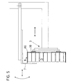
- a protective plate 7, which with the movement mechanism of the suction pad 3 is coupled, at least in part via the opening of the now swung filled box and preferably on these pressed so that the cans D are kept in the box are. These directions of movement are shown in FIG Arrows shown. It has been shown that it is sufficient if the protective plate is the top or more of the top Layers of cans D covered.
- the suction gripper 3 pulls the filled box 8 from the packaging station in horizontal and perpendicular to the feed direction direction back to the rear end position.
- the box thus also reaches the Transport plate slidable perpendicular to the loading direction, where them from the suction pad 3 by deactivating the negative pressure released by a press arm pressing on them from above held and with the transport plate to the processing station is passed on.
Abstract
Description
Die vorliegende Erfindung betrifft ein Verfahren zum Abpacken
von Dosen oder Tuben gemäss Oberbegriff des Patentanspruches
1. Es betrifft zudem eine Abpackmaschine zur Durchführung des
Verfahrens gemäss Oberbegriff des Patentanspruches 7.The present invention relates to a method for packaging
of cans or tubes according to the preamble of the
Anlagen zum Fertigen von Tuben oder Dosen sind äusserst kostspielig und müssen zu ihrer Amortisation möglichst mit voller Kapazität und ohne kostspielige Stand- und Umrüstzeiten betrieben werden. Eine Schlüsselstelle im Ablauf der Fertigung hin zum versandfertigen Produkt ist die Verpackung der losen Dosen oder Tuben. Die zwei gebräuchlichen Verpackungsarten für solche leere Gebinde sind die Verpackung in Schachteln und das Umreifen mit Bändern. Beide Verfahren weisen unterschiedliche Vor- und Nachteile auf. Die Umreifung ist dank des geringen Preises und Dank des geringen Volumens und Gewichtes der verwendeten Bänder ökonomisch und ökologisch sehr interessant. Da die dünnen Umreifungsbänder von Vorratsrollen kontinuierlich zugeführt und am Ort der Umreifung auf die passende Länge geschnitten werden, lassen sich Umreifungseinheiten äusserst platzsparend in den Abpackmaschinen integrieren. Andererseits schützt die Verpackung in Schachteln die Dosen und Tuben gegen Beschädigung und Verschmutzung, was zum Beispiel im pharmazeutischen und im Nahrungsmittelbereich von entscheidender Bedeutung ist. Lines for the production of tubes or cans are extremely expensive and have to be fully amortized if possible Capacity and without expensive downtimes and changeover times operate. A key point in the manufacturing process Towards the product ready for dispatch is the packaging of the lots Cans or tubes. The two common types of packaging for such empty containers are the packaging in boxes and that Strapping with straps. Both methods have different Advantages and disadvantages. The strapping is thanks to the low Price and thanks to the small volume and weight of the used Tapes economically and ecologically very interesting. There the thin strapping of supply rolls continuously fed and cut to the appropriate length at the location of the strapping strapping units can be extremely Space-saving integration in the packaging machines. On the other hand the packaging in boxes protects the cans and tubes Damage and pollution, for example in pharmaceutical and crucial in the food sector Meaning is.
Bisher stehen nur Abpackmaschinen zur Verfügung, die entweder zum Umreifen oder zum Abpacken der Dosen oder Tuben in Schachteln benutzt werden können. Ein Wechsel von der einen auf die andere Verpackungsart erfordert daher nicht nur zwei Maschinen sondern bringt auch einen erheblichen logistischen Aufwand zum Umrüsten der Fertigungsanlage im Verpackungsbereich, bzw. zum Transport der Dosen oder Tuben zu der jeweiligen Abpackeinheit mit sich.So far, only packaging machines are available that either for strapping or packing the cans or tubes in Boxes can be used. A change from one the other type of packaging therefore does not only require two Machines but also brings a significant logistical Expenditure for retrofitting the production system in the packaging area, or to transport the cans or tubes to the respective packaging unit with itself.
Bei den bekannten Anlagen zum Abpacken von Dosen oder Tuben in Schachteln stellt die Zuführung der leeren Schachtel hohe räumliche und mechanische Anforderungen an die Abpackvorrichtung, da die Schachteln oft waagrecht transportiert und zum Befüllen in die Senkrechte gekippt werden müssen, oder die Schachteln schrittweise beladen werden und dabei beweglich und exakt in verschiedene Lagen positioniert werden müssen. Dabei erfolgt die Zubringung der Schachteln im allgemeinen über Transportbänder.In the known systems for packing cans or tubes in Boxes feed the empty box high spatial and mechanical requirements for the packaging device, because the boxes are often transported horizontally and to the Filling must be tilted to the vertical, or the Boxes are loaded step by step while being mobile and must be positioned exactly in different positions. Here the boxes are generally fed via Conveyor belts.
Es ist daher Aufgabe der vorliegenden Erfindung, ein Verfahren und eine Vorrichtung zu schaffen, die in derselben Maschine einen einfachen Wechsel der Verpackungsart erlauben.It is therefore an object of the present invention to provide a method and to create a device operating in the same machine allow a simple change of the type of packaging.
Diese Aufgabe löst ein Verfahren mit den Merkmalen des Patentanspruches
1 und eine Vorrichtung mit den Merkmalen des
Patentanspruches 7.This object is achieved by a method with the features of the
Das erfindungsgemässe Verfahren verwendet eine Abpackmaschine mit auswechselbarem Verpackungsmodul, das in einer Ausführungsform zum Umreifen der Dosen oder Tuben und in einer weiteren Ausführungsform zum Abpacken der Dosen oder Tuben in Schachteln verwendet werden kann. Durch das blosse Auswechseln des Verpackungsmoduls kann von der Verpackungsart Umreifen auf die Verpackungsart Einfüllen in Schachteln, und umgekehrt, umgestellt werden, ohne dass umfangreiche und damit zeitintensive Umbauten an der Maschine vorgenommen werden müssen oder gar die gesamte Abpackmaschine ausgewechselt werden muss. Dies wird insbesondere dadurch ermöglicht, dass die Schachtelzuführung seitlich, das heisst senkrecht zur Abfüllrichtung der Dosen oder Tuben in die Schachtel, erfolgt. Dadurch lassen sich die Elemente Verpackungslehre und Sauggreifer sowohl für die Umreifung wie auch für die Schachtelabfüllung verwenden. Zudem lässt sich das Verpackungsmodul sehr schmal ausbilden, da die minimale Breite durch die Tiefe der zu füllenden Schachtel begrenzt wird.The method according to the invention uses a packaging machine with interchangeable packaging module, which in one embodiment for strapping the cans or tubes and in one another embodiment for packing the cans or tubes in Boxes can be used. By simply replacing of the packaging module can be strapped to the type of packaging the type of packaging, filling in boxes, and vice versa, be converted without extensive and thus time-consuming Modifications to the machine must be made or even the entire packaging machine has to be replaced. This is made possible in particular by the fact that the box feeder to the side, i.e. perpendicular to the filling direction the cans or tubes into the box. Thereby the elements of packaging gauges and suction pads both for strapping and for box filling use. In addition, the packaging module can be very narrow train because the minimum width by the depth of the filling box is limited.
Beim Wechsel der Verpackungsart genügt ein kurzer Unterbruch der Abpackmaschine, während dem das Verpackungsmodul ausgewechselt wird. Je nach Ausführungsform werden zudem geringe Anpassungen der Verpackungslehre und des Sauggreifers durchgeführt und das Steuerprogramm wird abgeändert.A brief interruption is sufficient when changing the type of packaging the packaging machine during which the packaging module is replaced becomes. Depending on the embodiment, will also be small Adjustments to the packaging gauge and the suction pad made and the control program is changed.
Da, bis auf die Wechselmodule, alle Komponenten der Abpackmaschine für beide Verpackungsarten verwendet werden, kann eine Abpackmaschine um den Preis des Wechselmoduls, der im Verhältnis zu den Anschaffungskosten einer solchen Maschine gering ist, um eine Verpackungsfunktion erweitert werden. Die Konstruktion des Schachtelfüllmoduls ermöglicht es unter Ausnutzung des modularen Aufbaus, dass alle zum Füllen einer Schachtel nötigen Dosen oder Tuben in einem Schritt und in einer gewünschten dichten Packung in die Schachtel gefüllt werden.There, apart from the interchangeable modules, all components of the packaging machine can be used for both types of packaging a packaging machine for the price of the interchangeable module, which in Ratio to the cost of such a machine is small to be expanded by a packaging function. The construction of the box filling module enables it under Utilization of the modular structure that all for filling one Box of necessary cans or tubes in one step and in a desired tight packing in the box will.
Ein weiterer Vorteil ist, dass die Verpackungsmodule auf verschiedenen Maschinen eingesetzt und zwischen Maschinen ausgetauscht werden können. Another advantage is that the packaging modules are on used different machines and exchanged between machines can be.
In den beiliegenden Zeichnungen ist ein Ausführungsbeispiel des Erfindungsgegenstandes dargestellt, anhand dessen das erfindungsgemässe Verfahren erläutert wird. Es zeigen
Figur 1- eine schematische Darstellung einer Abpackmaschine von der Seite;
- Figur 2a
- eine schematische Darstellung einer Abpackmaschine von oben mit dem Transportweg der Dosen;
- Figur 2b
- die Darstellung gemäss Figur a mit dem Transportweg der Schachtel;
Figur 3- eine Verpackungsstation von der Seite;
- Figur 4a
- die Verpackungsstation gemäss
Figur 3 von oben mit dem Weg des Schachtelträgers; - Figur 4b
- die Verpackungsstation gemäss Figur 4a mit dem Weg des Sauggreifers und
Figur 5- eine Detailansicht der Verpackungsstation mit einer Schutzplatte.
- Figure 1
- a schematic representation of a packaging machine from the side;
- Figure 2a
- a schematic representation of a packaging machine from above with the transport path of the cans;
- Figure 2b
- the representation according to Figure a with the transport path of the box;
- Figure 3
- a packing station from the side;
- Figure 4a
- the packaging station according to Figure 3 from above with the path of the box carrier;
- Figure 4b
- the packing station according to Figure 4a with the path of the suction pad and
- Figure 5
- a detailed view of the packaging station with a protective plate.
Im folgenden wird zum einfacheren Verständnis der Begriff Dosen verwendet, wobei Dosen, Tuben und ähnliche Behältnisse damit gemeint sind. Ferner wird als örtlicher Bezug die Lage der abgesenkten Verpackungslehre genommen, wobei jedoch die Verpackungslehre nicht zu jedem beschriebenen Zeitpunkt zwingend abgesenkt sein muss.In the following the term becomes easier to understand Cans used, with cans, tubes and similar containers are meant. The location is also used as a local reference the lowered packaging gauge, but the Packaging theory not at every point in time described must be lowered.
Aus den Figuren 1, 2a und 2b ist der schematische Aufbau der
erfindungsgemässen Abpackmaschine ersichtlich. In einer Förderstation
F wird jeweils eine Schicht Dosen D mittels eines
hier nicht dargestellten Schiebers in eine schrittweise absenkbare
Verpackungslehre 2 geschoben. Die Form der Verpackungslehre
2 entspricht dabei der Form der zu erzielenden
Verpackung. Sollen die Dosen D mit einem Band umreift werden,
weist die Verpackungslehre bevorzugterweise eine hexagonale
Form auf, wie in der Figur mit der Bezugszahl 2' gekennzeichnet
ist. Werden die Dosen D in Schachteln verpackt, entspricht
die Verpackungslehre 2 der Oeffnung der Schachtel und
ist, wie in der Figur 2a ersichtlich, bevozugterweise
rechteckig.FIGS. 1, 2a and 2b show the schematic structure of the
Packing machine according to the invention can be seen. In a conveyor station
F is a layer of cans D by means of a
slide not shown here in a gradually
Die Verpackungslehre 2 wird von der Förderstation F zur Verpackungsstation
V gefahren. In diesem Beispiel wird sie hierzu
abgesenkt. In der Verpackungsstation V werden die Dosen D
gemeinsam in Form einer dichten Packung aus der Verpackungslehre
2 entfernt, um sie mit einer gemeinsamen Verpackung zu
versehen. Die Weiterbeförderung erfolgt mittels eines Sauggreifers
3, welcher eine ebene Saugfläche aufweist, die
parallel zur Verpackungslehre ausgerichtet ist. Der Sauggreifer
3 ist in Richtung der Dosenabgabe aus der Verpackungslehre
2, der Abfüllrichtung, bewegbar und weist eine vordere
Endposition am Ort der Verpackung und eine hintere Endposition
auf, an welcher die verpackten Dosen D auf eine senkrecht zur
Abfüllrichtung verschiebbare Transportplatte gelangen, wo sie
von einem von oben auf sie drückenden Pressarm festgehalten
und mit dieser Transportplatte an eine nächstfolgende Bearbeitungsstation
B weitergegeben werden. In diesem Fall handelt es
sich bei der Bearbeitungsstation um eine Kontrollstation, bei
der die verpackten Dosen D auf ein Laufband in Augenhöhe angehoben
und leicht geneigt werden, so dass die Dosenböden zur
Reinheitskontrolle erkennbar sind. Der Transportweg der Dosen
D ist in Figur 2a mit Pfeilen dargestellt, wobei symbolisch
eine einzige Dose dargestellt ist. Der Verlauf des Verpackungsmaterials
ist für den Fall der Schachtelverpackung in
Figur 2b ersichtlich, wobei die Bewegungen a-g durchgeführt
werden; für den Fall der Umreifung entfallen die Bewegungen b
und c. The
Die Art der Verpackung ist wählbar zwischen Schachtelabfüllung
und Umreifung. Deshalb sind auswechselbare Verpackungsmodule
1,1' vorhanden, welche auf Rollen gelagert sind. Jeweils ein
Verpackungsmodul lässt sich in eine hierfür vorgesehene Bucht
der Abpackmaschine, genauer zwischen abgesenkter Verpackungslehre
2 und Sauggreifer 3, einschieben und mittels Justierrollen
oder Schienen exakt positionieren und arretieren. Jedes
Verpackungsmodul besteht aus einem Basalkörper, auf dem entweder
eine Schachtel- oder eine Bandzuführung angeordnet ist.
Das Verpackungsmaterial, das heisst die Schachtel oder das
Band, wird dabei in einer Ebene, der Zubringebene, zur Verpackungsstation
gebracht, welche senkrecht zur Richtung der
Abgabe der Dosen D aus der Verpackungslehre, der Abfüllrichtung,
liegt. Für beide Verpackungsarten werden die Verpackungslehre
2 und der Sauggreifer 3 benötigt. Sie können
deshalb identisch sein oder jedoch entsprechend der Form der
gewünschten Verpackung beim Wechseln des Verpackungsmoduls
ebenfalls ausgewechselt werden.
Wesentlich ist jedoch, dass dieselben Halterungen und Verschiebungsmechanismen
für alle Arten von Verpackungslehren
oder Sauggreifern verwendet werden.The type of packaging can be selected between box filling and strapping.
However, it is essential that the same holders and displacement mechanisms are used for all types of packaging gauges or suction cups.
Je nachdem, ob umreift oder in eine Schachtel abgefüllt wird, handelt es sich beim Verpackungsmodul um ein Umreifungs- oder ein Schachtelabfüllmodul.Depending on whether it is strapped or filled into a box, is the packaging module a strapping or a box filling module.
Das Umreifungsmodul besteht aus bekannten Elementen und ist deshalb hier nicht im Detail dargestellt. Auf dem Umreifungsmodul sind eine Bandrolle und Mittel zur Umreifung vorhanden. Die übrigen hier beschriebenen Elemente sind Teil der stationären Verpackungsmaschine. Die abgesenkte, mit Dosen D gefüllte Verpackungslehre wird in horizontaler Richtung auf das Umreifungsmodul gelenkt und das Band um die Dosen D geschlungen, abgeschnitten und die Enden verschweisst. Ein Sauggreifer mit mehreren Saugöffnungen wird auf der der Verpackungslehre abgewandten Seite zu den Dosen D hingeführt, wobei er mit Unterdruck die Dosen D ansaugt. Dabei sind die Dosen D so ausgerichtet, dass die Dosenböden zum Sauggreifer hingerichtet sind. Zugleich oder anschliessend wird die nun leere Verpackungslehre horizontal zurückgefahren und wieder zur Förderstation F angehoben. Der Sauggreifer wird in Laderichtung vom Ort der Verpackung zurückgefahren und führt dabei die umreiften Dosen D mit. In der hinteren Endposition gelangt das umreifte Dosenpaket 9 auf die senkrecht zur Laderichtung verschiebare Transportplatte, wird mit einem von oben auf das Umreifungspaket drückenden Pressarm festgehalten und mit dieser Transportplatte an die Bearbeitungsstation weitergegeben.The strapping module consists of known elements and is therefore not shown in detail here. On the strapping module there is a roll of tape and means for strapping. The remaining elements described here are part of the stationary packaging machine. The lowered, with cans D filled packing gauge is opened in the horizontal direction the strapping module steered and the strap around the cans D looped, cut and the ends welded. A Suction cup with several suction openings is on the packaging gauge opposite side to the cans D, whereby he draws the cans D with negative pressure. Here are the Can D aligned so that the can bottoms become a suction cup are executed. At the same time or afterwards it will now empty packaging gauge moved back horizontally and again raised to conveyor station F. The suction pad is in the loading direction drove back from the place of packaging and leads the strapped cans D with. Arrived in the rear end position the strapped can package 9 on the perpendicular to the loading direction slidable transport plate, is with a from above on the Strapping package pressing arm pressed and with this transport plate passed on to the processing station.
Das Schachtelabfüllmodul 1 ist in den Figuren 3, 4a und 4b
dargestellt. Das Schachtelabfüllmodul 1 weist einen vertikal
stehenden Schachtelträger 5 auf, welcher in der Zubringebene
von einer äusseren Endposition zu einer inneren, der Verpackungslehre
benachbarten Endposition bewegbar ist. In dieser
Ausführungsform wird der Schachtelträger 5 durch einen Wagen
gebildet, welcher mittels eines Linearzylinders 11 in horizontaler
Richtung entlang eines Schlitzes 12 im Schachtelabfüllmodul
1 hin und her fahrbar ist. In einer anderen Ausführungsform
ist der Schachtelträger ein Schwenkarm, welcher in der
Zubringebene schwenkbar ist.The
Der Schachtelträger 5 weist einen Tragarm 50 und mindestens
einen, hier drei, daran angeordnete, verstellbare Ausleger 51
auf. Er ist am besten in Figur 3 ersichtlich. Eine zu
füllende, offene Schachtel 8 wird in seitlicher Lage in der
äusseren Endposition auf den Schachtelträger 5 gestülpt.
Dieser ist dank dem verstellbaren Ausleger 51 auf die
Schachtelgrösse anpassbar. Tragarm und Ausleger sind so ausgebildet,
dass sich bei aufgesteckter Schachtel der Schachtelboden
auf der der Verpackungslehre abgewandten Seite befindet.
Die Oeffnung der Schachtel befindet sich somit seitlich. Falls
sich der Schachtelträger horizontal bewegt, wird die Schachtel
entsprechend der Ausrichtung der Verpackungslehre auf den
Schachtelträger gestülpt. Im Falle des schwenkbaren Schachtelträgers
wird die Schachtel um 90° gedreht angeordnet.The
Nun fährt der Schachtelträger 5 mit der Schachtel 8 zur Verpackungsstation
zwischen die abgesenkte Verpackungslehre 2 und
dem Sauggreifer 3 bis zu seiner inneren Endposition, welche in
der Figur 4a mit gestrichelten Linien dargestellt ist. Hier
wird die Schachtel 8 vom Sauggreifer 3 übernommen, wobei der
Sauggreifer 3 hierfür gleichzeitig oder anschliessend horizontal
in Richtung der abgesenkten Verpackungslehre geschoben
wird, bis er den Boden 80 der Schachtel 8 berührt. Er saugt
sich am Schachtelboden 80 fest und fährt mit der Schachtel vom
Schachtelträger 5 weg. In einer bevorzugten Ausführungsform
weist der Sauggreifer 3 eine viereckige Saugplatte mit
mindestens vier Saugnäpfen 30 auf, welche in den Ecken der
Saugplatte angeordnet sind.
Der Schachtelträger 5 wird nun mindestens soweit fortbewegt,
bis er die Oeffnung der Schachtel vollständig freigibt. Bevorzugterweise
wird er wieder in seine äussere Endposition
zurückgefahren, um eine neue Schachtel aufzunehmen. Der Sauggreifer
3 hingegen fährt mit der Schachtel 8 zur abgesenkten
Verpackungslehre 2, wie in Figur 4b mit gestrichelten Linien
dargestellt ist.Now the
The
Handelt es sich um eine Kartonschachtel, so wird die Schachtel
hier bevorzugterweise von einem Schachtelhalter 6 aufgenommen.
Dieser Schachtelhalter 6 ist stationär auf dem Schachtelfüllmodul
1 angeordnet und besteht aus einem Schachtelhalterrahmen
60 und mehreren, hier vier, verschiebbaren Klemmelementen 61.
Der Schachtelhalter 6 dient der Fixierung der Seitenwände der
Schachtel während deren Füllung. Die Klemmelemente 61 weisen
hierfür jeweils eine Schrägplatte auf, welche in die
Schachtelöffnung hineinragen und durch Verschieben die Seitenwände
leicht nach aussen pressen. Nun werden die Dosen D von
der Verpackungslehre 2 mittels eines hier nicht dargestellten
Schiebers in die Schachtel 8 geschoben, wobei die Schrägplatten
als Führung dienen.If it is a cardboard box, the box becomes
here preferably taken up by a
In einer bevorzugten Ausführungsform wird nun eine Schutzplatte
7, welche mit dem Bewegungsmechanismus des Sauggreifers
3 gekoppelt ist, mindestens teilweise über die Oeffnung der
nun gefüllten Schachtel geschwenkt und bevorzugterweise an
diese angepresst, damit die Dosen D in der Schachtel gehalten
sind. Diese Bewegungsrichtungen sind in der Figur 5 mit
Pfeilen dargestellt. Es hat sich gezeigt, dass es ausreicht,
wenn die Schutzplatte die oberste oder mehrere der oberen
Lagen der Dosen D überdeckt.In a preferred embodiment, a protective plate
7, which with the movement mechanism of the
Der Sauggreifer 3 zieht die gefüllte Schachtel 8 von der Verpackungsstation
in horizontaler und senkrecht zur Zubringrichtung
verlaufender Richtung zurück bis zur hinteren Endposition.
Die Schachtel gelangt somit ebenfalls auf die
senkrecht zur Laderichtung verschiebbare Transportplatte, wo
sie vom Sauggreifer 3 durch Desaktivierung des Unterdruckes
freigegeben, von einem von oben auf sie drückenden Pressarm
festgehalten und mit der Transportplatte an die Bearbeitungsstation
weitergegeben wird.The
Claims (11)
dadurch gekennzeichnet,
characterized,
dadurch gekennzeichnet,
characterized,
Applications Claiming Priority (2)
| Application Number | Priority Date | Filing Date | Title |
|---|---|---|---|
| CH2536/96 | 1996-10-17 | ||
| CH02536/96A CH691899A5 (en) | 1996-10-17 | 1996-10-17 | Method and apparatus for packaging cans or tubes. |
Publications (1)
| Publication Number | Publication Date |
|---|---|
| EP0836995A1 true EP0836995A1 (en) | 1998-04-22 |
Family
ID=4236014
Family Applications (1)
| Application Number | Title | Priority Date | Filing Date |
|---|---|---|---|
| EP97810599A Withdrawn EP0836995A1 (en) | 1996-10-17 | 1997-08-26 | Method and device for packaging cans or tubes |
Country Status (4)
| Country | Link |
|---|---|
| US (1) | US5862649A (en) |
| EP (1) | EP0836995A1 (en) |
| CA (1) | CA2218194A1 (en) |
| CH (1) | CH691899A5 (en) |
Cited By (1)
| Publication number | Priority date | Publication date | Assignee | Title |
|---|---|---|---|---|
| DE10316853B4 (en) * | 2003-04-11 | 2007-10-31 | Aisa Automation Industrielle S.A. | Device for automatic packaging of containers |
Families Citing this family (8)
| Publication number | Priority date | Publication date | Assignee | Title |
|---|---|---|---|---|
| AU7995900A (en) | 1999-10-15 | 2001-04-30 | Hartness International, Inc. | Continuous circular motion case packing and depacking apparatus and method |
| US7114535B2 (en) * | 2003-08-28 | 2006-10-03 | Hartness International, Inc. | Circular motion filling machine and method |
| US7278531B2 (en) * | 2004-06-29 | 2007-10-09 | Hartness International, Inc. | Flexible conveyor and connection elements |
| US7299832B2 (en) * | 2004-06-29 | 2007-11-27 | Hartness International, Inc. | Rotary filling machine and related components, and related method |
| US7331156B2 (en) * | 2004-06-29 | 2008-02-19 | Hartness International, Inc. | System for securely conveying articles and related components |
| ITTO20080318A1 (en) * | 2008-04-24 | 2009-10-25 | Elsag Datamat Spa | POSTAL OBJECT TREATMENT DEVICE PACKED |
| US10982384B2 (en) | 2016-05-24 | 2021-04-20 | Twine Solutions Ltd. | System, machine and method for treating threads or parts thereof |
| CN108438333A (en) * | 2018-03-30 | 2018-08-24 | 漳州杰安塑料有限公司 | A kind of selectapette box packing machine |
Citations (3)
| Publication number | Priority date | Publication date | Assignee | Title |
|---|---|---|---|---|
| FR2352709A1 (en) * | 1976-05-28 | 1977-12-23 | Alusuisse | METHOD AND DEVICE FOR PACKAGING CYLINDRICAL CONTAINERS |
| DE2825800A1 (en) * | 1978-03-17 | 1979-09-20 | Alusuisse | DEVICE FOR BAGGING IN ESSENTIAL CYLINDRICAL OBJECTS TO PACKAGES |
| US4386490A (en) * | 1981-04-13 | 1983-06-07 | Armour-Dial, Inc. | Apparatus for collating, cutting and packing food products |
Family Cites Families (12)
| Publication number | Priority date | Publication date | Assignee | Title |
|---|---|---|---|---|
| US5704A (en) * | 1848-08-10 | Aik-heatiwg stove | ||
| US3054236A (en) * | 1959-06-22 | 1962-09-18 | Vol Pak Inc | Multi-purpose packaging machine |
| US3383829A (en) * | 1966-02-02 | 1968-05-21 | James M. Duddleston | Combined paper carton and plastic bottle filling machine |
| US3465494A (en) * | 1967-05-04 | 1969-09-09 | Haskon Inc | Filling and sealing machine |
| US4534153A (en) * | 1983-07-11 | 1985-08-13 | Owens--Illinois, Inc. | Method and apparatus for packing plastic bottles |
| DE3339924A1 (en) * | 1983-11-04 | 1985-05-15 | Robert Bosch Gmbh, 7000 Stuttgart | PACKING MACHINE |
| DE3410685A1 (en) * | 1984-03-23 | 1985-10-03 | Robert Bosch Gmbh, 7000 Stuttgart | SIZE PACKAGING MACHINE |
| DE59002105D1 (en) * | 1990-01-25 | 1993-09-02 | Pamag Ag | METHOD FOR PACKING SLEEVES OR TUBES IN BOXES, AND MACHINE FOR CARRYING OUT THE METHOD. |
| CH683171A5 (en) * | 1991-04-04 | 1994-01-31 | Pamag Ag | Workpiece handling system in factory - incorporates several conveyor belts with receptacles holding workpieces |
| ZA945755B (en) * | 1993-08-11 | 1995-03-15 | Metal Box Co South Africa | The packaging of articles |
| ZA949233B (en) * | 1993-12-01 | 1995-08-01 | Metal Box Co South Africa | The packing of cylindrical articles. |
| US5636498A (en) * | 1995-05-12 | 1997-06-10 | George Gordon Associates, Inc. | Bulk straw loading system |
-
1996
- 1996-10-17 CH CH02536/96A patent/CH691899A5/en not_active IP Right Cessation
-
1997
- 1997-08-26 EP EP97810599A patent/EP0836995A1/en not_active Withdrawn
- 1997-10-14 US US08/949,579 patent/US5862649A/en not_active Expired - Fee Related
- 1997-10-14 CA CA002218194A patent/CA2218194A1/en not_active Abandoned
Patent Citations (3)
| Publication number | Priority date | Publication date | Assignee | Title |
|---|---|---|---|---|
| FR2352709A1 (en) * | 1976-05-28 | 1977-12-23 | Alusuisse | METHOD AND DEVICE FOR PACKAGING CYLINDRICAL CONTAINERS |
| DE2825800A1 (en) * | 1978-03-17 | 1979-09-20 | Alusuisse | DEVICE FOR BAGGING IN ESSENTIAL CYLINDRICAL OBJECTS TO PACKAGES |
| US4386490A (en) * | 1981-04-13 | 1983-06-07 | Armour-Dial, Inc. | Apparatus for collating, cutting and packing food products |
Cited By (1)
| Publication number | Priority date | Publication date | Assignee | Title |
|---|---|---|---|---|
| DE10316853B4 (en) * | 2003-04-11 | 2007-10-31 | Aisa Automation Industrielle S.A. | Device for automatic packaging of containers |
Also Published As
| Publication number | Publication date |
|---|---|
| CA2218194A1 (en) | 1998-04-17 |
| US5862649A (en) | 1999-01-26 |
| CH691899A5 (en) | 2001-11-30 |
Similar Documents
| Publication | Publication Date | Title |
|---|---|---|
| EP0298294B1 (en) | Apparatus for the grouping of packages | |
| DE2744158A1 (en) | DEVICE FOR PACKAGING COMPRESSIBLE ARTICLES, E.G. DISPOSABLE DIAPERS OR DIGITAL, IN CARTONS | |
| DE10127896B4 (en) | Transfer device and method for foil bags | |
| CH671566A5 (en) | ||
| EP0062249B1 (en) | Packaging machine | |
| WO2011104036A2 (en) | Method for changing the upper and lower tool of a packaging machine | |
| DE3813729A1 (en) | STACKING OF BANDS OF FLAT-FOLDED BOXES MADE OF CORRUGATED CARDBOARD | |
| EP0836995A1 (en) | Method and device for packaging cans or tubes | |
| DE3700146A1 (en) | Machine for strapping packages in the longitudinal and transverse directions | |
| DE102005002532A1 (en) | Device and method for automated and simultaneous provision and change of at least two rolls of paper webs or the like for a downstream format cutter | |
| EP0077992B1 (en) | Apparatus for check-weighing packages | |
| EP1975074B1 (en) | Device and method for loading and unloading a number of objects arranged in a receptacle with an upward opening | |
| DE4127854C2 (en) | Device for feeding two plate-shaped blanks to a deep-drawing machine | |
| EP1020359A2 (en) | Device for transporting objects and simultaneously turning them, especially folding boxes | |
| DE2304994C2 (en) | Device for introducing packs into transport containers | |
| DE3729373C2 (en) | ||
| DE3632691C2 (en) | ||
| DE2416579A1 (en) | Packing machine for item group into trays - has sliding transporter plate working below group segregation mechanism | |
| DE1228557B (en) | Conveyor device for use in a strapping or strapping machine | |
| DE2435671C3 (en) | Method and device for handling and storing elongated objects | |
| DE1611884C2 (en) | Device for feeding cardboard cut to a packaging device | |
| DE4210749C2 (en) | Device for introducing bag packs into a collecting container | |
| DE2001760C (en) | Device for introducing objects into a collecting container | |
| DE19945386A1 (en) | Method and device for packing plastic film wrapping rolls after producing rolls of plastic film at a winding point feeds plastic film wrapping rolls through one after the other in sequence passing them to a cassette in a manipulator. | |
| DE3718851A1 (en) | Apparatus for the transfer of cup sticks of predetermined length from a conveyor band into a carton or vice versa |
Legal Events
| Date | Code | Title | Description |
|---|---|---|---|
| PUAI | Public reference made under article 153(3) epc to a published international application that has entered the european phase |
Free format text: ORIGINAL CODE: 0009012 |
|
| AK | Designated contracting states |
Kind code of ref document: A1 Designated state(s): BE CH DE FR GB IT LI LU NL |
|
| AX | Request for extension of the european patent |
Free format text: AL;LT;LV;RO;SI |
|
| 17P | Request for examination filed |
Effective date: 19980924 |
|
| AKX | Designation fees paid |
Free format text: BE CH DE FR GB IT LI LU NL |
|
| RBV | Designated contracting states (corrected) |
Designated state(s): BE CH DE FR GB IT LI LU NL |
|
| RAP1 | Party data changed (applicant data changed or rights of an application transferred) |
Owner name: HINTERKOPF GMBH |
|
| GRAH | Despatch of communication of intention to grant a patent |
Free format text: ORIGINAL CODE: EPIDOS IGRA |
|
| STAA | Information on the status of an ep patent application or granted ep patent |
Free format text: STATUS: THE APPLICATION IS DEEMED TO BE WITHDRAWN |
|
| 18D | Application deemed to be withdrawn |
Effective date: 20030301 |