EP1123457B1 - Gas turbine engine - Google Patents
Gas turbine engine Download PDFInfo
- Publication number
- EP1123457B1 EP1123457B1 EP99968015A EP99968015A EP1123457B1 EP 1123457 B1 EP1123457 B1 EP 1123457B1 EP 99968015 A EP99968015 A EP 99968015A EP 99968015 A EP99968015 A EP 99968015A EP 1123457 B1 EP1123457 B1 EP 1123457B1
- Authority
- EP
- European Patent Office
- Prior art keywords
- combustor
- blades
- inlet portion
- fluid flow
- casing
- Prior art date
- Legal status (The legal status is an assumption and is not a legal conclusion. Google has not performed a legal analysis and makes no representation as to the accuracy of the status listed.)
- Expired - Lifetime
Links
Images
Classifications
-
- F—MECHANICAL ENGINEERING; LIGHTING; HEATING; WEAPONS; BLASTING
- F02—COMBUSTION ENGINES; HOT-GAS OR COMBUSTION-PRODUCT ENGINE PLANTS
- F02C—GAS-TURBINE PLANTS; AIR INTAKES FOR JET-PROPULSION PLANTS; CONTROLLING FUEL SUPPLY IN AIR-BREATHING JET-PROPULSION PLANTS
- F02C7/00—Features, components parts, details or accessories, not provided for in, or of interest apart form groups F02C1/00 - F02C6/00; Air intakes for jet-propulsion plants
- F02C7/12—Cooling of plants
- F02C7/16—Cooling of plants characterised by cooling medium
- F02C7/18—Cooling of plants characterised by cooling medium the medium being gaseous, e.g. air
-
- F—MECHANICAL ENGINEERING; LIGHTING; HEATING; WEAPONS; BLASTING
- F01—MACHINES OR ENGINES IN GENERAL; ENGINE PLANTS IN GENERAL; STEAM ENGINES
- F01D—NON-POSITIVE DISPLACEMENT MACHINES OR ENGINES, e.g. STEAM TURBINES
- F01D9/00—Stators
- F01D9/06—Fluid supply conduits to nozzles or the like
- F01D9/065—Fluid supply or removal conduits traversing the working fluid flow, e.g. for lubrication-, cooling-, or sealing fluids
-
- F—MECHANICAL ENGINEERING; LIGHTING; HEATING; WEAPONS; BLASTING
- F01—MACHINES OR ENGINES IN GENERAL; ENGINE PLANTS IN GENERAL; STEAM ENGINES
- F01D—NON-POSITIVE DISPLACEMENT MACHINES OR ENGINES, e.g. STEAM TURBINES
- F01D5/00—Blades; Blade-carrying members; Heating, heat-insulating, cooling or antivibration means on the blades or the members
- F01D5/02—Blade-carrying members, e.g. rotors
- F01D5/08—Heating, heat-insulating or cooling means
- F01D5/081—Cooling fluid being directed on the side of the rotor disc or at the roots of the blades
-
- F—MECHANICAL ENGINEERING; LIGHTING; HEATING; WEAPONS; BLASTING
- F01—MACHINES OR ENGINES IN GENERAL; ENGINE PLANTS IN GENERAL; STEAM ENGINES
- F01D—NON-POSITIVE DISPLACEMENT MACHINES OR ENGINES, e.g. STEAM TURBINES
- F01D9/00—Stators
- F01D9/02—Nozzles; Nozzle boxes; Stator blades; Guide conduits, e.g. individual nozzles
- F01D9/023—Transition ducts between combustor cans and first stage of the turbine in gas-turbine engines; their cooling or sealings
-
- F—MECHANICAL ENGINEERING; LIGHTING; HEATING; WEAPONS; BLASTING
- F01—MACHINES OR ENGINES IN GENERAL; ENGINE PLANTS IN GENERAL; STEAM ENGINES
- F01D—NON-POSITIVE DISPLACEMENT MACHINES OR ENGINES, e.g. STEAM TURBINES
- F01D9/00—Stators
- F01D9/02—Nozzles; Nozzle boxes; Stator blades; Guide conduits, e.g. individual nozzles
- F01D9/04—Nozzles; Nozzle boxes; Stator blades; Guide conduits, e.g. individual nozzles forming ring or sector
-
- F—MECHANICAL ENGINEERING; LIGHTING; HEATING; WEAPONS; BLASTING
- F02—COMBUSTION ENGINES; HOT-GAS OR COMBUSTION-PRODUCT ENGINE PLANTS
- F02C—GAS-TURBINE PLANTS; AIR INTAKES FOR JET-PROPULSION PLANTS; CONTROLLING FUEL SUPPLY IN AIR-BREATHING JET-PROPULSION PLANTS
- F02C7/00—Features, components parts, details or accessories, not provided for in, or of interest apart form groups F02C1/00 - F02C6/00; Air intakes for jet-propulsion plants
- F02C7/08—Heating air supply before combustion, e.g. by exhaust gases
-
- F—MECHANICAL ENGINEERING; LIGHTING; HEATING; WEAPONS; BLASTING
- F04—POSITIVE - DISPLACEMENT MACHINES FOR LIQUIDS; PUMPS FOR LIQUIDS OR ELASTIC FLUIDS
- F04D—NON-POSITIVE-DISPLACEMENT PUMPS
- F04D27/00—Control, e.g. regulation, of pumps, pumping installations or pumping systems specially adapted for elastic fluids
- F04D27/02—Surge control
- F04D27/0207—Surge control by bleeding, bypassing or recycling fluids
- F04D27/0215—Arrangements therefor, e.g. bleed or by-pass valves
-
- F—MECHANICAL ENGINEERING; LIGHTING; HEATING; WEAPONS; BLASTING
- F23—COMBUSTION APPARATUS; COMBUSTION PROCESSES
- F23R—GENERATING COMBUSTION PRODUCTS OF HIGH PRESSURE OR HIGH VELOCITY, e.g. GAS-TURBINE COMBUSTION CHAMBERS
- F23R3/00—Continuous combustion chambers using liquid or gaseous fuel
- F23R3/42—Continuous combustion chambers using liquid or gaseous fuel characterised by the arrangement or form of the flame tubes or combustion chambers
- F23R3/54—Reverse-flow combustion chambers
-
- Y—GENERAL TAGGING OF NEW TECHNOLOGICAL DEVELOPMENTS; GENERAL TAGGING OF CROSS-SECTIONAL TECHNOLOGIES SPANNING OVER SEVERAL SECTIONS OF THE IPC; TECHNICAL SUBJECTS COVERED BY FORMER USPC CROSS-REFERENCE ART COLLECTIONS [XRACs] AND DIGESTS
- Y02—TECHNOLOGIES OR APPLICATIONS FOR MITIGATION OR ADAPTATION AGAINST CLIMATE CHANGE
- Y02T—CLIMATE CHANGE MITIGATION TECHNOLOGIES RELATED TO TRANSPORTATION
- Y02T50/00—Aeronautics or air transport
- Y02T50/60—Efficient propulsion technologies, e.g. for aircraft
Definitions
- the invention relates to the field of gas turbine engines, and more specifically, to an improved gas turbine engine using a rotating fluid flow train to feed the combustor and enhance air/fuel mixing and emissions.
- a type of prior art gas turbine engine has a compressor, a fuel source, a combustion air source, a casing, and a combustor to prepare a heated fluid from fuel and and combustion air.
- the combustor is connected to the fuel source, the combustion air source and the compressor. Practically the entire fluid flow from the compressor is directed to the combustor.
- the engine has a turbine rotor disk with blades that receive the heated fluid from the combustor. As the turbine rotor disk rotates during engine operation, the heated fluid flow coming from the combustor has to be directed at an angle to the blades to ensure smooth entry conditions.
- the stator vane angle normally is chosen to accommodate the most optimum and prevailing turbine rotor disk operating conditions (speed). This solution is quite acceptable for gas turbine engines that have more or less stable operating conditions, such as when used for power generation. In applications where the load upon the gas turbine engine is steady, the turbine rotor disk rotates at a stable speed, and the entry angle for the blades remains unchanged thus minimizing losses. If, on the other hand, this gas turbine engine is used to power a vehicle, the situation is radically different. In that application, the turbine rotor disk speed will vary within a broad range depending on vehicle load. Consequently, the entry angle also varies within a broad range under load fluctuations, which leads to greater losses. This problem could not be solved by using the conventional approach with the stator vanes.
- controllable stator vanes it is possible to use controllable stator vanes to change the entry angle at the blades, but it is a very complicated and expensive solution given the high temperatures downstream of the combustor and space limitations. As a result, the gas turbine engine would have high losses in vehicle applications. Moreover, the stator and vanes occupies an additional space and makes the engine design more complicated and expensive. The use of controllable vanes makes the engine less reliable.
- Another object of the invention is to provide a more compact gas turbine engine that has a simpler design.
- Another object of the invention is to improve the emission characteristics of the gas turbine engine.
- a gas turbine engine has a device to admit a rotating fluid flow from an annular space in the casing to the inlet portion of a combustor to form a rotating fluid flow in the inlet portion of the combustor.
- the rotating fluid flow is formed in the annular space of the casing by supplying a fluid from a compressor to the blades of the turbine rotor disk.
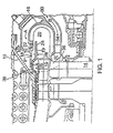
- a gas turbine engine has a casing 10, a compressor 12 for supplying a compressed fluid, a turbine rotor disk 14 mounted downstream of compressor 12 installed on the turbine rotor, a combustor 16 to prepare a heated fluid to be supplied to turbine rotor disk 14.
- Combustor 16 has a port 18 to admit fuel supplied from a fuel source (not shown).
- Combustor 16 defines a combustion zone 20 in which the heated fluid is formed.
- Combustion air is supplied from an air source (not shown) as shown by arrows A to an inlet portion of the combustor in which port 18 is provided.
- the inlet portion of the combustor shown at 19 is defined by an inner annular wall 22 of combustor 16 and by an annular guide wall 24 that extends within the combustor in a spaced relation to annular inner wall 22.
- Annular guide wall 24 is installed by brackets 26 in such a manner that a space 28 is left for fluid passage.
- a part of the fluid from compressor 12 is supplied to turbine rotor disk 14, bypassing combustor 16, as shown by arrows B, through passage 30 in casing 10 and reaching a zone 32 upstream of turbine rotor disk 14.
- Vanes 34 can be provided in passage 30 to make this fluid flow compatible with the turbine rotor disk 14 rotation. These vanes will function in an optimum manner only under certain turbine engine operating conditions. Since the quantity of fluid that is fed to the turbine rotor disk 14 and the velocity of this fluid are not very high, losses that would occur under non-optimum conditions would be relatively low. This fluid is admitted to turbine rotor disk 14 and envelops the blades 15.
- the fluid from the compressor 12 passes through a passage 36 of the blade 15 and leaves the passage 36 to reach an annular space 38 that is defined in casing 10 and surrounds blades 15.
- the fluid from the compressor 12 leaves blade passage 36 having obtained a rotation that forms a rotating fluid flow in annular space 38.
- This rotating fluid flow is admitted through space 28 to inlet portion 19 of combustor 16 to form a rotating fluid flow there.
- fuel is fed through port 18, it is entrained in a rotary motion by the rotating fluid flow in the inlet portion, and intense stirring and mixing of fuel and fluid will take place to prepare a good quality fuel mixture.
- the rotating fluid flow entrains air that is fed as shown by arrow A, moves into combustion zone 20, and imparts a spin to the heated fluid when it is formed in combustion zone 20.
- the direction of this rotating flow is the same as the turbine rotor disk direction of rotation and the velocity of this rotating flow steadily follows turbine rotor disk 14 rotation velocity (with a very short lag).
- the heated fluid formed in combustor 16 will move to the turbine blades 15 in a manner that is almost entirely compatible with rotation of the turbine rotor disk. Consequently, losses in this zone, which account for most of the losses in the turbine flow duct, are minimized.
- Another advantage of the invention is that the fluid from the compressor that goes through passage 36 and reaches blade 15 cools the blade and the adjacent wall of casing 10.
- Another advantage of the invention is the method of preparation of the fuel mixture.
- the quantity of fuel supplied for small-power gas turbine engines is rather low. It is very difficult to prepare a homogeneous fuel mixture with a ratio of fuel to air and fluid of 1:15 to 1:30.
- the fuel mixing method that is used here solves this problem. When fuel is entrained in a rotary motion by the rotating fluid flow admitted to the inlet portion of the combustor, fuel atomizing, mixing and stirring in the rotating flow are very thorough and intensive. This thoroughness assures a high degree of homogeneity of the fuel mixture.
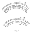
- Figure 2 shows an embodiment of the space (28) with annular guide walls (24) attached by brackets (26) (in Figure 1).
- Space (28) is shown in Figure 2 as referenced by cross-section II in Figure 1.
- This space (28) can take the form of an arc slit cut in a flanged portion of the annular guide wall or in the form of spaces between the adjacent brackets (not shown).
- Japanese Publication 111593345 (Pat. Appl. 09329192) teaches a conventional gas turbine engine in which the compressor flow is supplied to the turbine blades for cooling.
- the air from the compressor is fed to the combustor after cooling the turbine blades through a complex system of passages (see Fig. 12 of the Japanese publication).
- the fluid after the cooling is not fed to the combustor with a spin (or swirling velocity) that is equal to the velocity of rotation of the turbine disk adjacent to the combustor.
- the gas moving through the complex system of passages experiences high losses of energy and is only good for mixing or dilution of hot combustion products in the combustor before they leave the combustor and hit the blades of the first stage turbine.
- This combustor is of a conventional type with a dilution of mixing zone at the exit.
- the rotor disk of the first stage is not mounted immediately after the combustor; there is a set of nozzles (22) (Fig. 12);
- the flow of fluid that is used for cooling the blades does not perform useful work of expansion, and this flow is directed to the combustor for dilution which is associated with energy losses.
- the turbine rotor disk with blades ((23) in Fig. 12) is not positioned immediately downstream of the combustor (there is a set of nozzles - vanes (22) in Fig. 12 which direct the flow of fluid from the combustor to the turbine blades).
- No rotating flow is formed in the annular space. Since there is no such rotating flow, there is also no means for admitting a flow of rotating fluid to the combustor.
- the claimed inventions Teaches a turbine rotor disk (14) with blades (15) which are positioned immediately downstream of the combustor (16) for receiving the heated fluid from the combustor; an annular space (38) in the casing, the annular space surrounding the blades; a zone (32) located upstream of the turbine rotor disk and communicating with the compressor (12) for supplying a flow of fluid from the compressor to the blades to form a flow of rotating fluid in the annular space; and means for admitting the flow of rotating fluid from the annular space to the inlet portion of the combustor, whereby a rotating flow of fluid is formed in the inlet portion of said combustor.
- Publication RU 2050455 discloses a combustor that can be rotated with the rotor of the turbine compressor in order to assure the optimum angle of incidence during starting.
- the combustor also has a set of nozzles ((7) in Fig. 1) which determine the velocity of flow going to the first stage turbine.
- This cited publication does not show any means for providing a swirl in the combustor which follows up the circumferential velocity of the first stage turbine.
Landscapes
- Engineering & Computer Science (AREA)
- Mechanical Engineering (AREA)
- General Engineering & Computer Science (AREA)
- Chemical & Material Sciences (AREA)
- Combustion & Propulsion (AREA)
- Life Sciences & Earth Sciences (AREA)
- Sustainable Development (AREA)
- Physics & Mathematics (AREA)
- Fluid Mechanics (AREA)
- Structures Of Non-Positive Displacement Pumps (AREA)
- Turbine Rotor Nozzle Sealing (AREA)
Applications Claiming Priority (3)
| Application Number | Priority Date | Filing Date | Title |
|---|---|---|---|
| US161104 | 1993-12-02 | ||
| US09/161,104 US6460343B1 (en) | 1998-09-25 | 1998-09-25 | Gas turbine engine |
| PCT/US1999/020884 WO2000022287A2 (en) | 1998-09-25 | 1999-09-24 | Gas turbine engine |
Publications (2)
| Publication Number | Publication Date |
|---|---|
| EP1123457A2 EP1123457A2 (en) | 2001-08-16 |
| EP1123457B1 true EP1123457B1 (en) | 2003-11-19 |
Family
ID=22579835
Family Applications (1)
| Application Number | Title | Priority Date | Filing Date |
|---|---|---|---|
| EP99968015A Expired - Lifetime EP1123457B1 (en) | 1998-09-25 | 1999-09-24 | Gas turbine engine |
Country Status (9)
| Country | Link |
|---|---|
| US (2) | US20020152753A1 (enExample) |
| EP (1) | EP1123457B1 (enExample) |
| JP (1) | JP4263364B2 (enExample) |
| KR (1) | KR20010085843A (enExample) |
| CN (1) | CN1354819A (enExample) |
| AU (1) | AU2471400A (enExample) |
| CA (1) | CA2345341A1 (enExample) |
| DE (1) | DE69912982T2 (enExample) |
| WO (1) | WO2000022287A2 (enExample) |
Families Citing this family (5)
| Publication number | Priority date | Publication date | Assignee | Title |
|---|---|---|---|---|
| US6632070B1 (en) * | 1999-03-24 | 2003-10-14 | Siemens Aktiengesellschaft | Guide blade and guide blade ring for a turbomachine, and also component for bounding a flow duct |
| EP1532358B1 (en) * | 2002-06-26 | 2013-02-27 | R-Jet Engineering Ltd. | Orbiting combustion nozzle engine |
| US7225624B2 (en) * | 2004-06-08 | 2007-06-05 | Allison Advanced Development Company | Method and apparatus for increasing the pressure of cooling fluid within a gas turbine engine |
| US7836677B2 (en) * | 2006-04-07 | 2010-11-23 | Siemens Energy, Inc. | At least one combustion apparatus and duct structure for a gas turbine engine |
| US7631499B2 (en) * | 2006-08-03 | 2009-12-15 | Siemens Energy, Inc. | Axially staged combustion system for a gas turbine engine |
Family Cites Families (46)
| Publication number | Priority date | Publication date | Assignee | Title |
|---|---|---|---|---|
| US161114A (en) | 1875-03-23 | Improvement in hay-elevators | ||
| US161170A (en) | 1875-03-23 | Improvement in chain-propellers | ||
| US161115A (en) | 1875-03-23 | Improvement in car-springs | ||
| US1388707A (en) | 1918-10-01 | 1921-08-23 | John O Heinze | Turbine |
| GB196452A (en) | 1922-03-15 | 1923-04-26 | Henry Andrews Hepburn | Improvements in or relating to internal combustion turbine engines |
| US1868143A (en) | 1928-08-24 | 1932-07-19 | John O Heinze | Turbine |
| US2303381A (en) | 1941-04-18 | 1942-12-01 | Westinghouse Electric & Mfg Co | Gas turbine power plant and method |
| US2579049A (en) | 1949-02-04 | 1951-12-18 | Nathan C Price | Rotating combustion products generator and turbine of the continuous combustion type |
| GB727796A (en) | 1951-05-10 | 1955-04-06 | Nat Res Dev | Improvements relating to combustion equipment for burning liquid fuel and to gas turbine plant in which it is incorporated |
| GB753652A (en) | 1951-05-25 | 1956-07-25 | Vladimir Henry Pavlecka | A method of compressing a fluid |
| US2784551A (en) | 1951-06-01 | 1957-03-12 | Orin M Raphael | Vortical flow gas turbine with centrifugal fuel injection |
| GB801281A (en) | 1954-01-14 | 1958-09-10 | Robert Stephen Pollock | Improvements in or relating to reaction turbines |
| GB803994A (en) | 1954-07-27 | 1958-11-05 | Philip Peter Handfield Morton | Improvements in power units of the gas turbine type |
| US2821067A (en) | 1956-05-28 | 1958-01-28 | Boeing Co | Combustion chamber construction in a gas turbine engine |
| FR1340751A (fr) | 1962-12-11 | 1963-10-18 | Cem Comp Electro Mec | Perfectionnement aux turbines à combustion |
| US3287904A (en) | 1965-10-14 | 1966-11-29 | Warren Henry Russell | Gas turbine engine |
| US3469396A (en) | 1966-07-02 | 1969-09-30 | Shigeru Onishi | Gas turbine |
| DE2018641C2 (de) | 1970-04-18 | 1972-05-10 | Motoren Turbinen Union | Umkehrbrennkammer fuer gasturbinentriebwerke |
| US3826084A (en) | 1970-04-28 | 1974-07-30 | United Aircraft Corp | Turbine coolant flow system |
| US3727401A (en) | 1971-03-19 | 1973-04-17 | J Fincher | Rotary turbine engine |
| GB1435687A (en) | 1971-11-26 | 1976-05-12 | Chair R S De | Gas generators |
| US3971209A (en) | 1972-02-09 | 1976-07-27 | Chair Rory Somerset De | Gas generators |
| US3775974A (en) | 1972-06-05 | 1973-12-04 | J Silver | Gas turbine engine |
| NL7209417A (enExample) | 1972-07-06 | 1974-01-08 | ||
| FR2217546B3 (enExample) | 1973-02-09 | 1977-05-06 | Djordjenic Bozidar | |
| US3886732A (en) | 1973-09-27 | 1975-06-03 | Joseph Gamell Ind Inc | Internal combustion engine having coaxially mounted compressor combustion chamber, and turbine |
| US4024705A (en) | 1974-01-14 | 1977-05-24 | Hedrick Lewis W | Rotary jet reaction turbine |
| DE2437990A1 (de) | 1974-08-07 | 1976-02-26 | Rory Somerset De Chair | Gasturbinentriebwerk |
| US4151709A (en) * | 1975-09-19 | 1979-05-01 | Avco Corporation | Gas turbine engines with toroidal combustors |
| FR2385899A1 (fr) | 1977-03-29 | 1978-10-27 | Hedrick Lewis | Moteur a reaction |
| JPS5477820A (en) | 1977-12-02 | 1979-06-21 | Hitachi Ltd | Method of cooling gas turbine blade |
| WO1982000856A1 (en) | 1979-10-15 | 1982-03-18 | G Grim | Combination rotating fluidized bed combustor and heat exchanger |
| US4338781A (en) | 1979-11-01 | 1982-07-13 | Caterpillar Tractor Co. | Rotating fluidized bed combustor |
| US4549402A (en) | 1982-05-26 | 1985-10-29 | Pratt & Whitney Aircraft Of Canada Limited | Combustor for a gas turbine engine |
| US5003766A (en) * | 1984-10-10 | 1991-04-02 | Paul Marius A | Gas turbine engine |
| GB2189845B (en) | 1986-04-30 | 1991-01-23 | Gen Electric | Turbine cooling air transferring apparatus |
| US4845941A (en) * | 1986-11-07 | 1989-07-11 | Paul Marius A | Gas turbine engine operating process |
| US5054279A (en) | 1987-11-30 | 1991-10-08 | General Electric Company | Water spray ejector system for steam injected engine |
| US4991391A (en) | 1989-01-27 | 1991-02-12 | Westinghouse Electric Corp. | System for cooling in a gas turbine |
| US5280703A (en) * | 1989-12-11 | 1994-01-25 | Sundstrand Corporation | Turbine nozzle cooling |
| US5174108A (en) * | 1989-12-11 | 1992-12-29 | Sundstrand Corporation | Turbine engine combustor without air film cooling |
| SU1744290A1 (ru) | 1990-07-09 | 1992-06-30 | Казанский Авиационный Институт Им.А.Н.Туполева | Способ работы газотурбинной установки |
| CA2124069A1 (en) | 1993-05-24 | 1994-11-25 | Boris M. Kramnik | Low emission, fixed geometry gas turbine combustor |
| RU2050455C1 (ru) | 1993-11-22 | 1995-12-20 | Анатолий Михайлович Рахмаилов | Способ запуска газотурбинного двигателя и газотурбинный двигатель |
| US5727378A (en) * | 1995-08-25 | 1998-03-17 | Great Lakes Helicopters Inc. | Gas turbine engine |
| JP3887469B2 (ja) | 1997-11-28 | 2007-02-28 | 株式会社東芝 | ガスタービンプラント |
-
1998
- 1998-09-25 US US09/161,104 patent/US20020152753A1/en active Granted
- 1998-09-25 US US09/161,104 patent/US6460343B1/en not_active Expired - Fee Related
-
1999
- 1999-09-24 DE DE69912982T patent/DE69912982T2/de not_active Expired - Fee Related
- 1999-09-24 JP JP2000576164A patent/JP4263364B2/ja not_active Expired - Fee Related
- 1999-09-24 CN CN99812682A patent/CN1354819A/zh active Pending
- 1999-09-24 KR KR1020017003790A patent/KR20010085843A/ko not_active Withdrawn
- 1999-09-24 CA CA002345341A patent/CA2345341A1/en not_active Abandoned
- 1999-09-24 AU AU24714/00A patent/AU2471400A/en not_active Abandoned
- 1999-09-24 WO PCT/US1999/020884 patent/WO2000022287A2/en not_active Ceased
- 1999-09-24 EP EP99968015A patent/EP1123457B1/en not_active Expired - Lifetime
Also Published As
| Publication number | Publication date |
|---|---|
| CA2345341A1 (en) | 2000-04-20 |
| DE69912982D1 (de) | 2003-12-24 |
| AU2471400A (en) | 2000-05-01 |
| US6460343B1 (en) | 2002-10-08 |
| JP4263364B2 (ja) | 2009-05-13 |
| JP2002527707A (ja) | 2002-08-27 |
| US20020152753A1 (en) | 2002-10-24 |
| DE69912982T2 (de) | 2007-09-20 |
| EP1123457A2 (en) | 2001-08-16 |
| KR20010085843A (ko) | 2001-09-07 |
| WO2000022287A2 (en) | 2000-04-20 |
| WO2000022287A3 (en) | 2000-08-24 |
| CN1354819A (zh) | 2002-06-19 |
Similar Documents
| Publication | Publication Date | Title |
|---|---|---|
| US4018043A (en) | Gas turbine engines with toroidal combustors | |
| CA2520471C (en) | Methods and apparatus for assembling a gas turbine engine | |
| JPH0674754B2 (ja) | ガスタ−ビン機関 | |
| JPH08218896A (ja) | パワープラント | |
| US4265590A (en) | Cooling air supply arrangement for a gas turbine engine | |
| JPH03160143A (ja) | タンデム―ファン―エンジン | |
| EP1123457B1 (en) | Gas turbine engine | |
| JPH09501479A (ja) | 熱エネルギを機械的エネルギに変換する方法および装置 | |
| JPH06193461A (ja) | ガスタービン群 | |
| CN110168205B (zh) | 燃气涡轮发动机 | |
| US6305157B1 (en) | Gas turbine engine | |
| US6272844B1 (en) | Gas turbine engine having a bladed disk | |
| US10787965B1 (en) | Advanced gas turbine engine | |
| JP2022150946A (ja) | ガスタービン用燃焼器 | |
| RU2082894C1 (ru) | Газотурбинный двигатель | |
| JP7604731B2 (ja) | 燃焼器用ノズル、燃焼器およびこれを含むガスタービン | |
| JP3149612B2 (ja) | エアターボラムジェットエンジン | |
| JPS5985429A (ja) | ガスタ−ビン静翼の冷却装置 | |
| WO2000053897A1 (en) | Gas turbine engine | |
| JPH05256164A (ja) | 触媒燃焼器 | |
| JPH03151600A (ja) | 圧縮機組立体 | |
| JPH05256165A (ja) | 触媒燃焼器 | |
| GB2024326A (en) | Compressor arrangements | |
| CN108374732A (zh) | 一种静地冲压航空航天发动机及其使用方法和用途 | |
| JPH0776535B2 (ja) | 複式導入ラジアルタ−ビンガスゼネレ−タ |
Legal Events
| Date | Code | Title | Description |
|---|---|---|---|
| PUAI | Public reference made under article 153(3) epc to a published international application that has entered the european phase |
Free format text: ORIGINAL CODE: 0009012 |
|
| AK | Designated contracting states |
Kind code of ref document: A2 Designated state(s): AT BE CH CY DE DK ES FI FR GB GR IE IT LI LU MC NL PT SE |
|
| 17P | Request for examination filed |
Effective date: 20010425 |
|
| RAP1 | Party data changed (applicant data changed or rights of an application transferred) |
Owner name: ALM DEVELOPMENT, INC. |
|
| GRAH | Despatch of communication of intention to grant a patent |
Free format text: ORIGINAL CODE: EPIDOS IGRA |
|
| GRAS | Grant fee paid |
Free format text: ORIGINAL CODE: EPIDOSNIGR3 |
|
| GRAA | (expected) grant |
Free format text: ORIGINAL CODE: 0009210 |
|
| AK | Designated contracting states |
Kind code of ref document: B1 Designated state(s): CH DE FR GB LI SE |
|
| PG25 | Lapsed in a contracting state [announced via postgrant information from national office to epo] |
Ref country code: LI Free format text: LAPSE BECAUSE OF FAILURE TO SUBMIT A TRANSLATION OF THE DESCRIPTION OR TO PAY THE FEE WITHIN THE PRESCRIBED TIME-LIMIT Effective date: 20031119 Ref country code: CH Free format text: LAPSE BECAUSE OF FAILURE TO SUBMIT A TRANSLATION OF THE DESCRIPTION OR TO PAY THE FEE WITHIN THE PRESCRIBED TIME-LIMIT Effective date: 20031119 |
|
| REG | Reference to a national code |
Ref country code: GB Ref legal event code: FG4D |
|
| REG | Reference to a national code |
Ref country code: CH Ref legal event code: EP |
|
| REF | Corresponds to: |
Ref document number: 69912982 Country of ref document: DE Date of ref document: 20031224 Kind code of ref document: P |
|
| REG | Reference to a national code |
Ref country code: IE Ref legal event code: FG4D |
|
| PG25 | Lapsed in a contracting state [announced via postgrant information from national office to epo] |
Ref country code: SE Free format text: LAPSE BECAUSE OF FAILURE TO SUBMIT A TRANSLATION OF THE DESCRIPTION OR TO PAY THE FEE WITHIN THE PRESCRIBED TIME-LIMIT Effective date: 20040219 |
|
| REG | Reference to a national code |
Ref country code: CH Ref legal event code: PL |
|
| ET | Fr: translation filed | ||
| PLBE | No opposition filed within time limit |
Free format text: ORIGINAL CODE: 0009261 |
|
| STAA | Information on the status of an ep patent application or granted ep patent |
Free format text: STATUS: NO OPPOSITION FILED WITHIN TIME LIMIT |
|
| 26N | No opposition filed |
Effective date: 20040820 |
|
| PGFP | Annual fee paid to national office [announced via postgrant information from national office to epo] |
Ref country code: GB Payment date: 20060920 Year of fee payment: 8 |
|
| PGFP | Annual fee paid to national office [announced via postgrant information from national office to epo] |
Ref country code: FR Payment date: 20060922 Year of fee payment: 8 |
|
| PGFP | Annual fee paid to national office [announced via postgrant information from national office to epo] |
Ref country code: DE Payment date: 20060928 Year of fee payment: 8 |
|
| GBPC | Gb: european patent ceased through non-payment of renewal fee |
Effective date: 20070924 |
|
| PG25 | Lapsed in a contracting state [announced via postgrant information from national office to epo] |
Ref country code: DE Free format text: LAPSE BECAUSE OF NON-PAYMENT OF DUE FEES Effective date: 20080401 |
|
| REG | Reference to a national code |
Ref country code: FR Ref legal event code: ST Effective date: 20080531 |
|
| PG25 | Lapsed in a contracting state [announced via postgrant information from national office to epo] |
Ref country code: FR Free format text: LAPSE BECAUSE OF NON-PAYMENT OF DUE FEES Effective date: 20071001 |
|
| PG25 | Lapsed in a contracting state [announced via postgrant information from national office to epo] |
Ref country code: GB Free format text: LAPSE BECAUSE OF NON-PAYMENT OF DUE FEES Effective date: 20070924 |