US3775974A - Gas turbine engine - Google Patents
Gas turbine engine Download PDFInfo
- Publication number
- US3775974A US3775974A US00259550A US3775974DA US3775974A US 3775974 A US3775974 A US 3775974A US 00259550 A US00259550 A US 00259550A US 3775974D A US3775974D A US 3775974DA US 3775974 A US3775974 A US 3775974A
- Authority
- US
- United States
- Prior art keywords
- blades
- compressor
- combustion chamber
- casing
- fuel
- Prior art date
- Legal status (The legal status is an assumption and is not a legal conclusion. Google has not performed a legal analysis and makes no representation as to the accuracy of the status listed.)
- Expired - Lifetime
Links
Images


Classifications
-
- F—MECHANICAL ENGINEERING; LIGHTING; HEATING; WEAPONS; BLASTING
- F02—COMBUSTION ENGINES; HOT-GAS OR COMBUSTION-PRODUCT ENGINE PLANTS
- F02C—GAS-TURBINE PLANTS; AIR INTAKES FOR JET-PROPULSION PLANTS; CONTROLLING FUEL SUPPLY IN AIR-BREATHING JET-PROPULSION PLANTS
- F02C3/00—Gas-turbine plants characterised by the use of combustion products as the working fluid
- F02C3/14—Gas-turbine plants characterised by the use of combustion products as the working fluid characterised by the arrangement of the combustion chamber in the plant
Definitions
- General objects of my invention are to provide such powerplant which is of simple construction and readily and economically fabricated and assembled on a mass production basis; is lighter in weight and more efficient than comparable engines; is sturdy and durable and low in cost; may be employed as a turbo-jet engine or turbo-shaft engine, or any combination thereof for powering automobiles, aircraft, boats, trains, motorcycles, or in any other obvious and suitable applications wherein pure jet thrust, or drive shaft power, or any combination thereof, is required for mobile vehicular, or fixed power installations.
- Amore specific object of my invention is to provide a suitable engine which is economically capable of replacing the piston-type of internal combustion engine for the purpose of substantially reducing atmospheric pollution, particularly by eliminating all poisonous lead or other additives from fossil fuels and substantially reducing or eliminating the emission of carbon monoxide, nitrogen oxides, sulfur oxides and unburned hydrocarbons.
- Another object of my invention is to provide an engine which can utilize any combustible liquid or gaseous fluid, thereby making available to the public an infinite number of low cost fuels and better utilizing the many fractions obtainable from petroleumand coal and by. chemical synthesis, which heretofore could not be. utilized in the piston-type internal combustion engine without extensive modification.
- a preferred embodiment of my invention is comprised of a high speed rotating unit, hereinafter designated the rotor, which combines the Brayton cycle functions of mixing fuel and air, centrifugal compression of the combustible mixture, ignition of said combustible mixture, containment of the products of combustion, utilization of the kinetic energy developed through aunique turbine blading and power takeoff; a tubular casing within which are a front antifriction bearing and arear-anti-friction bearing, both axially located and providing support for said rotor;.a single, gravity fed fuel line leading to a single fuel nozzle located within a venturi tube and a needle valve controlled by mechanical linkage which meters the fuel flow; a plurality of spark gaps located within the rotating combustion chamber, where the mixture is ignited in front or upstream of a flame-holder screen, said spark gaps being energized by a spark jumping from a single spark plug electrode deriving its energy from a battery operated vibrator-type spark coil; an externally mounted fan rotating with said rotor and
- the simple fuel delivery system has obvious advantages over the prior art in which bulky, complex, costly controlling devices and multiple pressurized fuel lines and fuel nozzles are employed.
- centrifugal compressor section of the closed-type, from whence it is driven at a right angle radially outward toward the combustion chamber.
- This type of centrifugal. compressor section hasseveral distinct advantages over prior art centrifugal compressors.
- Prior art centrifugal compressors require a closemachined fit between rotating and non-rotating parts, with attendant high costs of precision casting and machining.
- the compressor maybe assembled from sheet metal. stampings secured. by welding on an assembly line, resulting in low costs.
- Prior art centrifugal compressors force the fluid mass under compression to one hundred and eighty degree reversals of flow, resulting in reduced efficiency.
- Prior art axial flow compressors require energy-robbing stator blades after each compressor blade stage with repeated 90 reversals of flow resulting in reduced efficiency.
- the fluid mass makes one 90 turn perpendicular to the ambient air flow, then makes a second 90 turn back to a parallel flow until it enters the. turbine blading. No energy-robbing stators impede the flow or cause repeated changes of direction, resulting in a more efficient engine.
- the preferred embodiment of my invention draws the fuel/air mixture into the first of three parallel compressor sections, from whence it is impelled radially outward into the combustion chamber where it is ignited by a series of sparks from said plurality of spark gaps.
- the second and third compressor sections deliver an excess of oxygen and cooling air, as well as, increasing the air mass density within said rotating combustion chamber.
- the embodiment is not limited to three compressor sections, but may incorporate a plurality of such sections.
- a unique characteristic of my invention is the fact that the combustion fluid is continuously under the pressure of centrifugal force from the moment it enters the combustion fluid entrance chamber, until it completes the cycle of compression and expansion through the turbine wheel. This tends to contain the kinetic energy of the burning gases, until it can be properly utilized in the turbine wheel resulting in greater efficiency.
- a diffuser annulus .within the rotating combustion chamber converts the high speed, low pressure fluid from said compressor sections, to low speed, high pressure fluid thereby increasing the efficiency of combustion anddelivering more energy.
- each distinctively shaped blade forms aconverging-diverging reaction nozzle with each adjacent blade, resulting in a high speed flow of the combustion fluid and controlled expansion, resulting in greater power and efficiency.
- a typical example of a converging-diverging nozzle is the powerful and highly efficient rocket engine nozzle.
- the blades are fabricated from an easily molded, high temperature resistant ceramic, preferably high purity aluminum oxide fired at a temperature of approximately 3,000 F., or other suitable ceramic material, thus effecting a considerable reduction in weight and costs with simplicity of fabrication lending itself to efficient mass production.
- my invention may drive a power shaft directly or through suitable gearing. It may also be employed as a jet engine utilizing reaction thrust, or acombination of jet reaction thrust with a turbo-fan propulsion system.
- My invention departs from prior art in a third form of power takeoff, particularly suitable for automobiles, or other similar wheeled vehicles by driving a high speed rotary hydraulic pump and transmission of the high pressure hydraulic fluid, by means of tubing, to hydraulic motors located within said wheels or adjacent thereto.
- My engine does not require leaded fuels.
- An excess of oxygen common in gas turbine engines, prevents the formation of carbon monoxide and the emission of unburned hydrocarbons.
- the use of low sulfur fuels reduce or eliminate the formation and emission of sulfur oxides. Comparatively lower temperatures and pressures in the engine of my invention results in a substantial reduction of nitrogen oxide emissions.
- the general utilization of the engine of my invention would substantially reduce atmospheric pollution and provide an economical powerplant for an infinite numberof applications.
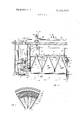
- FIG. 1 is a front elevational view with parts broken away, of an embodiment of my invention
- FIG. 2a is an axial section, with parts in elevation taken substantially on line 2ab-22b of FIG. 1;
- FIG. 2b is a continuation of FIG. 2a;
- FIG. 3 is a transverse section taken substantially on line 3-3 of FIG. 22;
- FIG. 4 is a side elevational view of a turbine blade, illustrating the positioning stubs
- FIG. 5 is a plan view of turbine blades in position along the periphery of the turbine wheel, illustrating the converging-diverging nozzle formed by adjacent I blades;
- FIG. 6 is a sectional view of a gear box driven by the engine drive shaft, illustrating the manner in which the starter motor is connected to the engine through said drive shaft, as well as, the oil pressure and oil scavenging pumps and final power takeoff;
- FIG. 7 is a rear elevational view of an embodiment of my invention with parts broken away.
- an embodiment of the improved gas turbine engine of my invention may comprise a tubular casing 1, within which are four supporting arms 34, 35, 36, 37 held in place by bolts 2, 3, 4, 5, which are secured to said casing by nuts 10, 11, l2, l3. Said arms in turn, support a bearing holder 101, within which is the front antifriction bearing sealed against leakage by oil seals 21, 22.
- a front engine support hub 59 which is an integral part of the rotor, rotates within said front bearing.
- Pressurized oil from an accessory drive oil pressure pump flows into manifold 29 through oil line 32 and T fitting 31, from whence it is distributed to front and rear antifriction bearings for the purpose of cooling and lubricating said bearings.
- Said pressurized oil flows down through a passage drilled through the center of bolt 5 within arm 34, thence to said front anti-friction bearings and down through drilled passage 88 at the center of bolt 3, and returned through line 23 to the scavenging pump and back to the oil tank.
- Fuel nozzle 57 is attached to the lower end of fuel line 54. Said fuel nozzle is controlled by needle valve 56 operated by control rod 51 through right angle link 52 supported by bracket 53. Said fuel nozzle is aligned parallel to the air flow entering said chamber 135. Fuel is drawn from said fuel nozzle by the passage of air through venturi 58, which crates a low pressure area at the tip of said nozzle.
- Lips 65 of the centrifugal compressor impeller vanes impel the fuel/air mixture radially outward into the combustion chamber, at the front of which is an externally attached cooling fan 86, which cools the external skin of said combustion chamber. Only a small portion of the skin 60 of said combustion chamber is visible in FIG. 1.
- Single electrode spark plug 82 energized by a battery operated vibrator spark coil or simlilar device, delivers a continuous stream of sparks, during the starting phase, to a plurality of spark gaps located within said combustion chamber where ignition occurs upstream of a flame-holder screen.
- Power shaft 48 extends downward and enters a gear box.
- FIG. 2a further illustrates a portion of said tubular casing 1, support arm 34, support bolt 5, bearing holder 101 and front anti-friction bearing 20, within which front engine support hub 59 rotates.
- Oil pressure line 32 delivers high pressure oil through said "1" fitting 31, through manifold line 29, down through passage 18, into passage 19 to front bearing 20, from which it is drained 88 in bottom bolt 3.(FIG. 1).
- Fuel line 54 passes down through casing 1, through support bracket 55 andis directly attached to fuel nozzle 57 controlled by needle valve 56, operated by control rod 51, through link 52, supporte dby bracket 53. Arrows indicate the flow of air through venturi 58, which draws fuel from nozzle 57. The fuel/air mixture, due to the off center location of said fuel. nozzle, enters the'first section of a plurality of parallel, closed-type centrifugal compressor sections, the impellers of which are indicated by numerals 64, 69, 72.
- Front engine support 59 is attached to integral combustion chamber outer skin 60 by means of rivets 61, or other suitable means.
- a reinforcing, pan shaped flanged disc 62 is attached to front extension of said combustion chamber skin 60, where said plate, in turn, supports and is secured to the front wall of the first compressor section 63.
- Impeller blades 64 are secured to said front wall and to the rear wall 67, which completes a single, closed-type centrifugal compressor section.
- Wall 67 is secured to support annulusl05, to which is secured front wall 68 of a second centrifugal compressor section.
- Impellers 69 are secured to said front wall 68 and to rear wall 70 of said second section. Said rear wall is secured to annular support ring 104, to which is secured front wall 71 of a third centrifugal compressor section. Impeller, blades 72 and rear wall 73 completes said third section.
- Each of the said walls is, in fact, an annular disc, which is press-formed from suitable sheet metal, preferably stainless steel Type 321, to the shape of a dish with a flange bent down at the periphery.
- suitable sheet metal preferably stainless steel Type 321
- each section tapers out ward toward the periphery, for the purpose of further compressing the entering fuel/air. mixture through the first section, and for the purpose of compressing the air entering the succeeding sections.
- the fuel/air mixture flows throughsaid first section,
- the air entering from the succeeding compressor sections cools the metal components of the combustion chamber, internally, and adds to the air mass density therein.
- the centrifugal force acting upon the combustion fluid during combustion tends to contain the kinetic energy developed, until said combustion fluid enters the turbine blading.
- Externally attached fan 86 blows air through the annular space between casing 1 and combustion chamber skin 60, cooling said skin.
- Posts 79 secure the compressor sections, the annular diffuser and the combustion chamber skin 60 into a strong, rigid unit.
- the combustion chamber outer wall orskin and diffuser annulus are press-formed from sheet-metal, preferably Type 321 Stainless steel. This is not to preclude the use of any other method of fabrication, whether sheet metal, casting, forging or. other suitable means or material that accomplishes thesame result.
- Pan-shaped flanged disc 74 is securedto rear wall 73 of the last compressor section .by welding and to the front segment of. the turbine wheel,pan-shaped disc 89, by means of bolts 93 and fastenedby nuts 94 as illustrated in FIG. 2b.
- the central axial portion of said discs is secured, together with similar discs 90, 91 by means of bolts95 and secured to drive shaft 49 by meansof nuts 96.
- the flanges of the pan-shaped turbine discs are notched to permit insertion, at an appropriate angle, of the turbine blade stubsinto the periphery of said turbine wheel.
- Spacer92 separates said pan-shaped discs at an appropriate distance for secure fastening.
- the outer. ends of said turbine blades are positioned by similar stubs projecting into, holes in. the periphery of combustion chamber skin 60and aligned with similar holes in reinforcing annulus 89.
- Turbine blades. 87 are shaped to form a convergingdiverging reaction nozzle between each blade and each adjacent blade.
- the material from which the bladesare fabricated is a high temperature ceramic such as high purity aluminum oxide, or other suitable material which is resistant to thermal shock, erosion and melting. Molded ceramic blades, which may be easily fabricated. in precision molds with their inherently accurate repeatability, have obvious cost and mass production advantages over prior art metal blades. The foregoing, is not to preclude the use of metal in blade fabrication.
- the rotor is supported on anti-friction bearings at the rear by means of four support arms similar to those at the front.
- Bolt 6 istthreaded into the rear bearing holder annulus 103 through tail cone 43.
- the portion of the arm within said cone supports said cone internally and is numbered 42.
- the portion of the arm 38 without said cone is fabricated from a suitable flame-resistant ceramic or other material capable of protecting said support arm from the heat of the exhaust gases.
- Said protective cover also serves as a spacer between said tail cone and atubular section 102, which serves to direct and contain said exhaust gases.
- said tail cone and tubular section may be attached to an exhaust chamber and appropriate piping.
- said tail cone and tubular section may be further shaped to form an efficient jet nozzle exiting directly to the ambient air stream.
- Pan-shaped disc 44 forms an end support for said tail cone.
- High pressure lubricating and cooling oil is carried by manifold line 30 down through drilled passage 28 in support bolt 6, tosaid rear anti-friction bearings 24, 25 sealed against leakage on one side by seals 26,27. Thence through drive shaft passage 108 into gear box 45, back through passage 109, in said shaft 49, and down through passage 29 drilledl through lower bolt.
- a spacer 114 completes the support column and permits tightening of nut 15 on bolt 6 without deformation of the bearing supports.
- the lower arm support within said tail cone is numbered 40 and similar components are arranged at the other two lateral positions.
- FIG. 3 better illustrates the arrangement of said impeller blades 64 and intermediate impeller blades 66, deflection and support annulus 76, diffuser annulus 75, annular flame-holder screen 78, combustion chamber outer wall or skin 60, reinforcing annulus 89 and tubular casing 1.
- FIG. 4 illustrates the arrangement of the positioning and retention stubs 99, 100, 106, 107 of the turbine wheel blades 87.
- FIG. 5 is a plan view illustrating the method of notching the two pan-shaped turbine wheel discs 89, 90. Equally spaced notches 118, 119 are cut into each disc; the discs are rotated to the position shown and secured by bolts 93, 95, which are aligned so as to hold the blades at an appropriate angle so as to form the converging-diverging reaction nozzle space between adjacent blades. The unique shape of said turbine blades is also apparent. The arrows indicate the flow of the combustion fluid through the blading.
- FIG. 6 illustrates the final drive gear box 121, in which anti-friction bearings typified by 120, one side sealed typified by seal 134, support the various shafts.
- Shaft 48 drives miter gear 122, which is in mesh with miter gears 123 and 126.
- Miter gear 122 drives shaft 124 by means of gear 123.
- Miter gear 123 drives miter gear 126, which drives spur gear oil pressure pump 127.
- Spur gear oil scavenging pump 130 is driven by miter gear 128, which is in mesh with miter gear 129.
- the engine is started by starter motor 131 driving shaft 124 by means of spur gear 132 in mesh with spur gear 133.
- Said starter motor may remain in mesh and generate an electric current, during engine operation, or it may be automatically disconnected by means of a Bendix spring drive.
- Splinedsection 125 of shaft 124 may be utilized to drive a large capacity hydraulic pump, which, in turn, may be employed to transmit high pressure hydraulic fluid to hydraulic motors operating vehicular driving wheels.
- the starter switch is turned on causing a battery to energize starter motor 131.
- the ignition switch is turned on and the throttle is opened slightly. A fuel/air mixture is drawn into the compressor section where it is impelled into the combustion chamber and ignited by a series of sparks jumping from the spark plug to the external electrodes of the combustion chamber spark gaps, across said spark gaps and grounded.
- the ignition switch is turned off and combustion is continuous as fresh fuel/air mix enters the chamber filled with burning combustion fluid.
- Speed is controlled by operating the fuel metering needle valve within the fuel nozzle.
- FIG. 7 is a rear view of the engine, illustrating the tubular casing l, the spark plug 82, the spark gap electr electrodes 80, 83, 84, 85, which within the combustion chamber.
- Oil pressure line 32 carries lubricating and cooling oil through T fitting 31 and to the rear antifriction bearings as described heretofore.
- Spacers 114, 115, 116, 117 separate the tubular casing from the exhaust section and provide a continuation of the flame resistant ceramic support arms 38, 39, 40, 41.
- the tapering tail cone 43 allows proper expansion of exhaust gases for jet operation.
- a pan-shaped disc 44 supports the end of the tail cone and encloses the gear box for protection from hot gases.
- Support bolts 8, 9 are secured by nuts 14, 16 to the outer casing. Nuts 15, 17 secure the other arms.
- Turbine blades 87 are visible from the rear.
- Scavenge oil line is connected to 33, and drive shaft 48 is connected to the final drive gear box.
- a constant volume, continuous combustion turbine engine comprising:
- an elongated housing open at each end having front and rear anti-friction bearings axially located therein;
- a rotor comprising:
- a plurality of parallel closed-type centrifugal compressor sections rotatably mounted within said casing and affixed thereto, with said compressor inlet extending through the axis of each compressor section ending at the forward wall of the turbine wheel, and communicating with the outlets of the compressor sections;
- an elongated, cylindrical combustion chamber comprising an annular space concentric with the axis of rotation, defined by and communicating with the compressor outlets at its inner radius, the cylindrical casing at its outer radius, a confinuation of said casing forming a forward wall perpendicular to the axis of rotation, and extending back to the turbine blades;
- annular diffuser rotatably mounted within said casing and affixed thereto, having suitable perforations therethrough and peripherally disposed around and spaced from the compressor outlets, the perforations providing communicating flow paths between the several compressor outlets and the combustion chamber;
- a means of initiating self-sustaining ignition of the fuel/air mixture comprising a plurality of spark gaps located within said combustion chamber at its forward end near the outlet of the first compressor section, rotatably mounted and affixed thereto, said gaps receiving current jumping from a fixed spark plug attached to the housing and aligned with said spark gaps;
- annular flame-holder rotatably mounted within said combustion chamber' and affixed thereto, comprising a suitable screen material downstream from said spark gaps, the open mesh of said screen material forming flow paths for combusting gases communicating and intermixing with the air flow from successive compressor section outlets through the diffuser, said flameholder preventing extinction of the ignited fuellair mixture;
- a turbine wheel rotatably mounted at the rear end of the cylindrical casing, having a plurality of combusted gas-receiving blades attached to said casing at their tips and the turbine wheel at their roots, said blades being interposed directly in the path of the combusted gas flow from the combustion chamber, at an optimum angle to the flow path;
- a means of coolingthe outer surface of the cylindrical casing comprising a plurality of airimpelling blades, circularly disposed and rotatably mounted at the front end of said casing and affixed thereto, interposed between the ambient air flow and the annular air space separating the casing from the housing;
- a means of introducing fuel into the combustion chamber comprising a fuel line attached to the housing and extending toward the air inlet at the front of the cylindrical casing, located excentrically near the first compressor inlet and communicating with the combustion chamber through said first compressor section;
- a combination accessory drive, power take-off and starter-generator means comprising a drive shaft affixed to theturbine wheel and supporting the rear end of the rotor in said axially located rear bearing,
- each first wall, each second wall and the blades therebetween defining a flow path between the axial air inlet and the combustion chamber;
- each section is attached to the adjacent section at the rims of their center holes, said rims defining a central air inlet space extending the length of the several compressor sections, the first wall of the first section being attached to the from opening of the cylindrical casing, the second wall of each section being attached to the first wall of each successive section, and the second wall of the last section being attached to the turbine wheel.
- a driving wheel with attached drive shaft affixed to the axis and providing a rear rotor support point, said wheel having a first flanged disk and a second flanged disk, the edges of said flanges contacting each other, having notches cut into each flange at equal intervals and said disks being fastened together;
- a plurality of combusted gas-receiving blades forming converging-diverging reaction nozzles in the space between any two blades, inserted into said wheel at the periphery, said spacing providing optimum restriction at the coverging space between said blades to permit optimum compression and combustion of thcignited fuel/air mixture in the combustion chamber before passage into the diverging space between said blades.
- bustion chamber by:
- a nozzle at the air-inlet end of said line having a needle valve for modulating the fuel flow
- a venturi tube encircling said nozzle, the ambient air flow drawing fuel from said nozzle under the influence of said venturi tube, and the fuel/air mixture passing into the forward end of the combusand a wide inlet at the axis;
- turbine engine comprising:
- each compressor section comprises: mounted within said housing, having openings at a. a first and second disk, each having a hole of suiteach end, one end being the air inlet at the front able diameter at in axis, forming: of the engine, the opposite, containing a turbine i. a first axisymmetrically tapered wall; wheel being theexhaust end; ii. a second axisymmetrically tapered wall spaced ii.
- each wall sloping toward the compressors, rotatably mounted within said oasother forming a narrow outlet at the periphery ing and affixed thereto, with said air inlet extending through the axis of each compressor and communicating with the peripheral outlets of each compressor;
- an elongated, cylindrical combustion chamber comprising an annular space concentric with the axis of rotation, defined by the compressor outlets at its inner radius, the cylindrical casing at its outer radius, a continuation of said casing forming a forward wall, and extending rearward ending at the turbine blades;
- an annular diffuser rotatably mounted within said casing and affixed thereto, having suitable perforations therethrough and peripherally disposed around and spaced from the compressor outlets, said diffuser slowing the high speed, low pressure air from said compressors and changing it to low speed, high pressure air, while directing it for optimum intermixing with the burning fuellair mixture in the combustion chamber;
- a means of igniting the fuel/air mixture comprising a plurality of spark gaps located within said combustion chamber at its forward end, rotatably mounted and affixed thereto, said gaps receiving current jumping from fixed spark plugs attached to the housing;
- annular flame-holder rotatably mounted within said combustion chamber and affixed thereto comprising a suitable screen material located near said spark gaps and preventing the flame of the burning fuel/air mixture from being extinguished;
- a turbine wheel rotatably mounted at the rear end of the cylindrical casing, having a plurality of combusted gas-receiving blades attached to said casing at their tips and the turbine wheel at their roots, said blades being rectangular in plan having substantially thick rounded leading edges, tapering chordwise to thin trailing edges, one side of each blade being substantially flat and the opposite side undulating, forming a substantially rectangular converging-diverging reaction nozzle between any two adjacent blades coacting in their turbine wheel positions in accordance with Newtons Third Law of Motion;
- a means of cooling the outer surface of the cylindrical casing comprising a plurality of airimpelling blades, circularly disposed and rotatably mounted at the forward end of said casing and affixed thereto, and propelling ambient air through the annular space separating said casing from the housing;
- a means of introducing fuel into the combustion chamber comprising a fuel line attached to the housing and extending toward the air inlet at the front of the cylindrical casing, located excentrically near the first compressor inlet and communicating with the combustion chamber through said first compressor section, said fuel line having a nozzle encircled by a venturi tube with a needle valve controlling the fuel flow at said air inlet;
- a combination accessory drive, power take-off and starter-generator means comprising a drive shaft affixed to the turbine wheel at its axis and supporting the rear end of the rotorin said axially located rear bearing, and communicating through suitable gearing with a gear box having power take-off shaft, accessory drive shafts and starter-generator shafts projecting therefrom.
- the combusted gas-receiving blades are fabricated of a suitable ceramic material capable of withstanding substantially high temperatures without melting, and having a plurality of stubs projecting from the tips and the roots, said root stubs being inserted into notches in the turbine wheel and said tip stubs being inserted in'holes cut through the cylindrical casing and through a reinforcing annulus encircling said casing, said blades being subjected primarily to compressive rather than tensile centrifugal forces.
Abstract
A high speed rotating unit which combines the Brayton cycle functions of mixing fuel and air, centrifugal compression of the combustible mixture, ignition of the said combustible mixture, containment of the products of combustion and utilization of the kinetic energy developed through a unique turbine blading and power take-off.
Description
4/1948 Cooke (SO/39.34
I UIlltEd States Patent [1 1 3,775,974 Silver Dec. 4, 1973 [54] GAS TURBINE ENGINE 3,287,904 11/1966 Warren et al 60/3934 1,197,340 9/1916 Carlson 60/3934 [7-6] Invent: Jack l 12052 Blackmer 3,626,694 12 1971 Holste 60/3936 Fountain Valley, Cahf. 92645 22 Filed; June '5 1972 Primary Examiner-Al Lawrence Smith Assistant Examiner-Warren Olsen [21] Appl. No.: 259,550
[57] ABSTRACT [52] Cl. 60/3934, 60/3936 A high speed rotating unit which combines the Bray- [51] Int. Cl. F02c 3/14 ton cycle functions of mixing fuel and air, centrifugal [58] Field of Search 60/3934, 39.35, compression of the combustible mixture, ignition of 60/3936, 3 9.31 the said combustible mixture, containment of the products of combustion and utilization of the kinetic [56] I References Cited energy developed through a unique turbine blading UNITED STATES PATENTS and Power take-01f 2,439,717 7 Claims, 8 Drawing Figures /5 I |||I V W/ /;m////////////////////////// 1 8.9 E l 3W4 60 /02 m i J 1:ln';ff;j Z
Z5 96 5a m 44 /os- 95 24 g 35 me m m v 27 //I 1/ i I 26 m Q 47 lo} n //2 H H} //3 2a 48 Dec. 4, 1973 United States Patent [1 1 Silver PATENTED 4 I MM] l U? 5 2 III III In I GAS TURBINE ENGINE My invention relates to gas turbine engines for both fixed and mobile installations on land, on water and in the air.
General objects of my invention are to provide such powerplant which is of simple construction and readily and economically fabricated and assembled on a mass production basis; is lighter in weight and more efficient than comparable engines; is sturdy and durable and low in cost; may be employed as a turbo-jet engine or turbo-shaft engine, or any combination thereof for powering automobiles, aircraft, boats, trains, motorcycles, or in any other obvious and suitable applications wherein pure jet thrust, or drive shaft power, or any combination thereof, is required for mobile vehicular, or fixed power installations.
Amore specific object of my invention is to provide a suitable engine which is economically capable of replacing the piston-type of internal combustion engine for the purpose of substantially reducing atmospheric pollution, particularly by eliminating all poisonous lead or other additives from fossil fuels and substantially reducing or eliminating the emission of carbon monoxide, nitrogen oxides, sulfur oxides and unburned hydrocarbons.
. Another object of my inventionis to provide an engine which can utilize any combustible liquid or gaseous fluid, thereby making available to the public an infinite number of low cost fuels and better utilizing the many fractions obtainable from petroleumand coal and by. chemical synthesis, which heretofore could not be. utilized in the piston-type internal combustion engine without extensive modification.
A preferred embodiment of my invention is comprised of a high speed rotating unit, hereinafter designated the rotor, which combines the Brayton cycle functions of mixing fuel and air, centrifugal compression of the combustible mixture, ignition of said combustible mixture, containment of the products of combustion, utilization of the kinetic energy developed through aunique turbine blading and power takeoff; a tubular casing within which are a front antifriction bearing and arear-anti-friction bearing, both axially located and providing support for said rotor;.a single, gravity fed fuel line leading to a single fuel nozzle located within a venturi tube and a needle valve controlled by mechanical linkage which meters the fuel flow; a plurality of spark gaps located within the rotating combustion chamber, where the mixture is ignited in front or upstream of a flame-holder screen, said spark gaps being energized by a spark jumping from a single spark plug electrode deriving its energy from a battery operated vibrator-type spark coil; an externally mounted fan rotating with said rotor and cooling the outer skin of said rotating combustion chamber; and a gearbox drive, which combines the functions of engine start, accessory drive and power takeoff either directly, or as in the preferred wheeled vehicular embodiment, indirectly through transmission of hydraulic fluid pressure developed by a suitable pump, to hydraulic motors located in juxtaposition to said wheels or other similar motive means.
In the preferred embodiment of my invention the simple fuel delivery system has obvious advantages over the prior art in which bulky, complex, costly controlling devices and multiple pressurized fuel lines and fuel nozzles are employed.
From the singlefuel nozzle, fuel drawn into the central, axially located entrance chamber at the hub of the rotor entersa centrifugal compressor section of the closed-type, from whence it is driven at a right angle radially outward toward the combustion chamber. This type of centrifugal. compressor sectionhasseveral distinct advantages over prior art centrifugal compressors.
First. Prior art centrifugal compressors require a closemachined fit between rotating and non-rotating parts, with attendant high costs of precision casting and machining. In my invention the compressor maybe assembled from sheet metal. stampings secured. by welding on an assembly line, resulting in low costs.
Second. Even with a close fit between rotating and non-rotating parts, an appreciable amount of pressure is lost through fluid bypass in prior art centrifugal compressors. The same is true of prior art axial, flow compressors in which fluid bypass occursat the tips of the compressor blades. resulting in reduced efficiency. In my invention no such loss can occur, due to. the fact that the impellers are totally enclosed and the fluid enters at the very axis of rotation.
Third. Prior art centrifugal compressors force the fluid mass under compression to one hundred and eighty degree reversals of flow, resulting in reduced efficiency. Prior art axial flow compressors require energy-robbing stator blades after each compressor blade stage with repeated 90 reversals of flow resulting in reduced efficiency. In my inventionthe fluid mass makes one 90 turn perpendicular to the ambient air flow, then makes a second 90 turn back to a parallel flow until it enters the. turbine blading. No energy-robbing stators impede the flow or cause repeated changes of direction, resulting in a more efficient engine.
The preferred embodiment of my invention draws the fuel/air mixture into the first of three parallel compressor sections, from whence it is impelled radially outward into the combustion chamber where it is ignited by a series of sparks from said plurality of spark gaps. The second and third compressor sections deliver an excess of oxygen and cooling air, as well as, increasing the air mass density within said rotating combustion chamber. The embodiment is not limited to three compressor sections, but may incorporate a plurality of such sections.
A unique characteristic of my invention is the fact that the combustion fluid is continuously under the pressure of centrifugal force from the moment it enters the combustion fluid entrance chamber, until it completes the cycle of compression and expansion through the turbine wheel. This tends to contain the kinetic energy of the burning gases, until it can be properly utilized in the turbine wheel resulting in greater efficiency.
A diffuser annulus .within the rotating combustion chamber converts the high speed, low pressure fluid from said compressor sections, to low speed, high pressure fluid thereby increasing the efficiency of combustion anddelivering more energy.
Since the first gas turbine engine was invented, near the close of World War II, there has been little change in the basic design of turbine blading. Prior art gasturbine blading invariably took the form of thin crosssectioned blades forming a relatively wide entrance between the blades, which rapidly decreased to a narrow exit. Under such arrangement turbulence must result as the gases leave the blading with attendant reduced efficiency.
In the blading of my invention, each distinctively shaped blade forms aconverging-diverging reaction nozzle with each adjacent blade, resulting in a high speed flow of the combustion fluid and controlled expansion, resulting in greater power and efficiency.
A typical example of a converging-diverging nozzle is the powerful and highly efficient rocket engine nozzle.
In the preferred embodiment of my invention the blades are fabricated from an easily molded, high temperature resistant ceramic, preferably high purity aluminum oxide fired at a temperature of approximately 3,000 F., or other suitable ceramic material, thus effecting a considerable reduction in weight and costs with simplicity of fabrication lending itself to efficient mass production.
As in prior art gas turbines, my invention may drive a power shaft directly or through suitable gearing. It may also be employed as a jet engine utilizing reaction thrust, or acombination of jet reaction thrust with a turbo-fan propulsion system.
My invention departs from prior art in a third form of power takeoff, particularly suitable for automobiles, or other similar wheeled vehicles by driving a high speed rotary hydraulic pump and transmission of the high pressure hydraulic fluid, by means of tubing, to hydraulic motors located within said wheels or adjacent thereto.
My engine does not require leaded fuels. An excess of oxygen, common in gas turbine engines, prevents the formation of carbon monoxide and the emission of unburned hydrocarbons. The use of low sulfur fuels reduce or eliminate the formation and emission of sulfur oxides. Comparatively lower temperatures and pressures in the engine of my invention results in a substantial reduction of nitrogen oxide emissions. Thus, it will be seen that the general utilization of the engine of my invention would substantially reduce atmospheric pollution and provide an economical powerplant for an infinite numberof applications.
. Other objects of my invention will in part be obvious and will in part appear hereinafter.
My invention, accordingly, comprises the features of construction, combination of elements and arrangement of parts, which will be exemplified in the construction hereinafter set forth, and the scope of my invention will be indicated in the claims.
For a fuller understanding of the nature and objects of my invention, reference should be had to the following detailed description taken in connection with the accompanying drawings, in which:
FIG. 1 is a front elevational view with parts broken away, of an embodiment of my invention;
FIG. 2a is an axial section, with parts in elevation taken substantially on line 2ab-22b of FIG. 1;
FIG. 2b is a continuation of FIG. 2a;
FIG. 3 is a transverse section taken substantially on line 3-3 of FIG. 22;
FIG. 4 is a side elevational view of a turbine blade, illustrating the positioning stubs;
FIG. 5 is a plan view of turbine blades in position along the periphery of the turbine wheel, illustrating the converging-diverging nozzle formed by adjacent I blades;
FIG. 6 is a sectional view of a gear box driven by the engine drive shaft, illustrating the manner in which the starter motor is connected to the engine through said drive shaft, as well as, the oil pressure and oil scavenging pumps and final power takeoff;
FIG. 7 is a rear elevational view of an embodiment of my invention with parts broken away.
Referring to the drawings, in which like numerals identify similar parts throughout, it will be seen from FIGS. 1 t0 7 inclusive, that an embodiment of the improved gas turbine engine of my invention, looking first at FIG. 1, may comprise a tubular casing 1, within which are four supporting arms 34, 35, 36, 37 held in place by bolts 2, 3, 4, 5, which are secured to said casing by nuts 10, 11, l2, l3. Said arms in turn, support a bearing holder 101, within which is the front antifriction bearing sealed against leakage by oil seals 21, 22.
A front engine support hub 59, which is an integral part of the rotor, rotates within said front bearing. Pressurized oil from an accessory drive oil pressure pump, flows into manifold 29 through oil line 32 and T fitting 31, from whence it is distributed to front and rear antifriction bearings for the purpose of cooling and lubricating said bearings. Said pressurized oil flows down through a passage drilled through the center of bolt 5 within arm 34, thence to said front anti-friction bearings and down through drilled passage 88 at the center of bolt 3, and returned through line 23 to the scavenging pump and back to the oil tank.
It may be preferredto substitute a casting or forging in place of said arms, support bolts and bearing holder. Similar oil passages may be drilled through such casting or forging.
Single electrode spark plug 82, energized by a battery operated vibrator spark coil or simlilar device, delivers a continuous stream of sparks, during the starting phase, to a plurality of spark gaps located within said combustion chamber where ignition occurs upstream of a flame-holder screen. Power shaft 48 extends downward and enters a gear box.
The components mentioned above, which have not been designated by a numeral, will be fully described and numbered later herein.
FIG. 2a further illustrates a portion of said tubular casing 1, support arm 34, support bolt 5, bearing holder 101 and front anti-friction bearing 20, within which front engine support hub 59 rotates. Oil pressure line 32 delivers high pressure oil through said "1" fitting 31, through manifold line 29, down through passage 18, into passage 19 to front bearing 20, from which it is drained 88 in bottom bolt 3.(FIG. 1).
Front engine support 59 is attached to integral combustion chamber outer skin 60 by means of rivets 61, or other suitable means. A reinforcing, pan shaped flanged disc 62 is attached to front extension of said combustion chamber skin 60, where said plate, in turn, supports and is secured to the front wall of the first compressor section 63. Impeller blades 64 are secured to said front wall and to the rear wall 67, which completes a single, closed-type centrifugal compressor section. Wall 67 is secured to support annulusl05, to which is secured front wall 68 of a second centrifugal compressor section.
Each of the said walls is, in fact, an annular disc, which is press-formed from suitable sheet metal, preferably stainless steel Type 321, to the shape of a dish with a flange bent down at the periphery. When secured, preferably by welding, each section tapers out ward toward the periphery, for the purpose of further compressing the entering fuel/air. mixture through the first section, and for the purpose of compressing the air entering the succeeding sections.
The fuel/air mixture flows throughsaid first section,
. is compressed and defelected by support annulus 76 and difiuserannulus 75 toward spark gaps 80, where the fuel/air mixture is ignited upstream from flameholder screen 78; The products of combustion pass through said screen, where said products of combustion mix with incoming compressed air through holes 77 in said diffuser annulus.
The air entering from the succeeding compressor sections cools the metal components of the combustion chamber, internally, and adds to the air mass density therein. The centrifugal force acting upon the combustion fluid during combustion, tends to contain the kinetic energy developed, until said combustion fluid enters the turbine blading.
Externally attached fan 86 blows air through the annular space between casing 1 and combustion chamber skin 60, cooling said skin.
As with components of the compressor sections, including walls and impeller blades, the combustion chamber outer wall orskin and diffuser annulus are press-formed from sheet-metal, preferably Type 321 Stainless steel. This is not to preclude the use of any other method of fabrication, whether sheet metal, casting, forging or. other suitable means or material that accomplishes thesame result.
Pan-shaped flanged disc 74 is securedto rear wall 73 of the last compressor section .by welding and to the front segment of. the turbine wheel,pan-shaped disc 89, by means of bolts 93 and fastenedby nuts 94 as illustrated in FIG. 2b. The central axial portion of said discs is secured, together with similar discs 90, 91 by means of bolts95 and secured to drive shaft 49 by meansof nuts 96. b v
The flanges of the pan-shaped turbine discs are notched to permit insertion, at an appropriate angle, of the turbine blade stubsinto the periphery of said turbine wheel. Spacer92 separates said pan-shaped discs at an appropriate distance for secure fastening. l
The outer. ends of said turbine blades are positioned by similar stubs projecting into, holes in. the periphery of combustion chamber skin 60and aligned with similar holes in reinforcing annulus 89.
Turbine blades. 87 are shaped to form a convergingdiverging reaction nozzle between each blade and each adjacent blade. Preferably the material from which the bladesare fabricated is a high temperature ceramic such as high purity aluminum oxide, or other suitable material which is resistant to thermal shock, erosion and melting. Molded ceramic blades, which may be easily fabricated. in precision molds with their inherently accurate repeatability, have obvious cost and mass production advantages over prior art metal blades. The foregoing, is not to preclude the use of metal in blade fabrication.
It should be bornin mind that the components from the front engine support hub 59, back to the drive shaft 49 and all those secured together between them, are integrated into a single, high speed rotating unit designated the rotor as aforesaid.
The rotor is supported on anti-friction bearings at the rear by means of four support arms similar to those at the front. Bolt 6 istthreaded into the rear bearing holder annulus 103 through tail cone 43. The portion of the arm within said cone supports said cone internally and is numbered 42. The portion of the arm 38 without said cone, is fabricated from a suitable flame-resistant ceramic or other material capable of protecting said support arm from the heat of the exhaust gases. Said protective cover also serves as a spacer between said tail cone and atubular section 102, which serves to direct and contain said exhaust gases.
In a wheeled vehicular application, said tail cone and tubular section may be attached to an exhaust chamber and appropriate piping. In a jet engine application, said tail cone and tubular section may be further shaped to form an efficient jet nozzle exiting directly to the ambient air stream.
High pressure lubricating and cooling oil is carried by manifold line 30 down through drilled passage 28 in support bolt 6, tosaid rear anti-friction bearings 24, 25 sealed against leakage on one side by seals 26,27. Thence through drive shaft passage 108 into gear box 45, back through passage 109, in said shaft 49, and down through passage 29 drilledl through lower bolt.
Snap-ring 50 and retainer ring 98, secured by bolts 97, resist axial thrust on said rear bearings. A spacer 114 completes the support column and permits tightening of nut 15 on bolt 6 without deformation of the bearing supports. The lower arm support within said tail cone is numbered 40 and similar components are arranged at the other two lateral positions.
I Anti-friction bearings 110, 112 with one-side seals 111 113, support the shafts as illustrated and miter gear 46 meshes with miter gear 47 to drive shaft 48, which extends downward into a second gear box.
FIG. 3 better illustrates the arrangement of said impeller blades 64 and intermediate impeller blades 66, deflection and support annulus 76, diffuser annulus 75, annular flame-holder screen 78, combustion chamber outer wall or skin 60, reinforcing annulus 89 and tubular casing 1.
FIG. 4 ilustrates the arrangement of the positioning and retention stubs 99, 100, 106, 107 of the turbine wheel blades 87.
FIG. 5 is a plan view illustrating the method of notching the two pan-shaped turbine wheel discs 89, 90. Equally spaced notches 118, 119 are cut into each disc; the discs are rotated to the position shown and secured by bolts 93, 95, which are aligned so as to hold the blades at an appropriate angle so as to form the converging-diverging reaction nozzle space between adjacent blades. The unique shape of said turbine blades is also apparent. The arrows indicate the flow of the combustion fluid through the blading.
FIG. 6 illustrates the final drive gear box 121, in which anti-friction bearings typified by 120, one side sealed typified by seal 134, support the various shafts. Shaft 48 drives miter gear 122, which is in mesh with miter gears 123 and 126. Miter gear 122 drives shaft 124 by means of gear 123. Miter gear 123 drives miter gear 126, which drives spur gear oil pressure pump 127. Spur gear oil scavenging pump 130 is driven by miter gear 128, which is in mesh with miter gear 129.
The engine is started by starter motor 131 driving shaft 124 by means of spur gear 132 in mesh with spur gear 133. Said starter motor may remain in mesh and generate an electric current, during engine operation, or it may be automatically disconnected by means of a Bendix spring drive. Splinedsection 125 of shaft 124 may be utilized to drive a large capacity hydraulic pump, which, in turn, may be employed to transmit high pressure hydraulic fluid to hydraulic motors operating vehicular driving wheels.
To start the engine, the starter switch is turned on causing a battery to energize starter motor 131. When the rotor reaches a predetermined speed, the ignition switch is turned on and the throttle is opened slightly. A fuel/air mixture is drawn into the compressor section where it is impelled into the combustion chamber and ignited by a series of sparks jumping from the spark plug to the external electrodes of the combustion chamber spark gaps, across said spark gaps and grounded. When the combustion process has commenced, the ignition switch is turned off and combustion is continuous as fresh fuel/air mix enters the chamber filled with burning combustion fluid. Speed is controlled by operating the fuel metering needle valve within the fuel nozzle.
FIG. 7 is a rear view of the engine, illustrating the tubular casing l, the spark plug 82, the spark gap electr electrodes 80, 83, 84, 85, which within the combustion chamber. Oil pressure line 32 carries lubricating and cooling oil through T fitting 31 and to the rear antifriction bearings as described heretofore.
Scavenge oil line is connected to 33, and drive shaft 48 is connected to the final drive gear box.
It will thus be seen that the objects set forth above, among those made apparent from the preceding description, are efficiently attained and, since certain changes may be made in the above construction and different embodiments of my invention could be made without departing from the scope thereof, it is intended that all matter contained in the above description, or shown in the accompanying drawings shall be interpreted as illustrative and not in a limiting sense.
It is also to be understood that the following claims are intended to cover all of the generic and specific features of the invention herein described, and all statements of the scope of the invention which, as a matter of language, might be said to fall therebetween.
Having described my invention, what I claim as new and desire to secure by Letters Patent is:
1. A constant volume, continuous combustion turbine engine, comprising:
a. an elongated housing open at each end having front and rear anti-friction bearings axially located therein;
b. a rotor, comprising:
i. an elongated, cylindrical casing rotatably mounted within said housing, having openings at .gas
each end, one opening of suitable diameter being the compressor inlet, the opposite end containing a turbine wheel; I
. a plurality of parallel closed-type centrifugal compressor sections, rotatably mounted within said casing and affixed thereto, with said compressor inlet extending through the axis of each compressor section ending at the forward wall of the turbine wheel, and communicating with the outlets of the compressor sections;
iii. an elongated, cylindrical combustion chamber, comprising an annular space concentric with the axis of rotation, defined by and communicating with the compressor outlets at its inner radius, the cylindrical casing at its outer radius, a confinuation of said casing forming a forward wall perpendicular to the axis of rotation, and extending back to the turbine blades;
iv. an annular diffuser rotatably mounted within said casing and affixed thereto, having suitable perforations therethrough and peripherally disposed around and spaced from the compressor outlets, the perforations providing communicating flow paths between the several compressor outlets and the combustion chamber;
v. a means of initiating self-sustaining ignition of the fuel/air mixture, comprising a plurality of spark gaps located within said combustion chamber at its forward end near the outlet of the first compressor section, rotatably mounted and affixed thereto, said gaps receiving current jumping from a fixed spark plug attached to the housing and aligned with said spark gaps;
vi. an annular flame-holder rotatably mounted within said combustion chamber' and affixed thereto, comprising a suitable screen material downstream from said spark gaps, the open mesh of said screen material forming flow paths for combusting gases communicating and intermixing with the air flow from successive compressor section outlets through the diffuser, said flameholder preventing extinction of the ignited fuellair mixture;
vii. a turbine wheel rotatably mounted at the rear end of the cylindrical casing, having a plurality of combusted gas-receiving blades attached to said casing at their tips and the turbine wheel at their roots, said blades being interposed directly in the path of the combusted gas flow from the combustion chamber, at an optimum angle to the flow path;
viii. a means of coolingthe outer surface of the cylindrical casing, comprising a plurality of airimpelling blades, circularly disposed and rotatably mounted at the front end of said casing and affixed thereto, interposed between the ambient air flow and the annular air space separating the casing from the housing;
c. a means of introducing fuel into the combustion chamber comprising a fuel line attached to the housing and extending toward the air inlet at the front of the cylindrical casing, located excentrically near the first compressor inlet and communicating with the combustion chamber through said first compressor section; v
d. a combination accessory drive, power take-off and starter-generator means, comprising a drive shaft affixed to theturbine wheel and supporting the rear end of the rotor in said axially located rear bearing,
i. a first edge conforming'in shape to the first wall and affixed at its inner side;
ii. a second edge conforming in shape to the second wall and affixed to its inner side;
iii. and the root of each blade forming a scoop bent in the direction of rotation and extending into the air inlet space at the axis;
c. each first wall, each second wall and the blades therebetween defining a flow path between the axial air inlet and the combustion chamber;
d. each section is attached to the adjacent section at the rims of their center holes, said rims defining a central air inlet space extending the length of the several compressor sections, the first wall of the first section being attached to the from opening of the cylindrical casing, the second wall of each section being attached to the first wall of each successive section, and the second wall of the last section being attached to the turbine wheel.
4. The gas turbine engine defined by claim 1, wherein the turbine wheel comprises;
a. a driving wheel with attached drive shaft affixed to the axis and providing a rear rotor support point, said wheel having a first flanged disk and a second flanged disk, the edges of said flanges contacting each other, having notches cut into each flange at equal intervals and said disks being fastened together;
b. a plurality of combusted gas-receiving blades, forming converging-diverging reaction nozzles in the space between any two blades, inserted into said wheel at the periphery, said spacing providing optimum restriction at the coverging space between said blades to permit optimum compression and combustion of thcignited fuel/air mixture in the combustion chamber before passage into the diverging space between said blades.
5. The gas turbine engine defined by claim ll, wherein bustion chamber, by:
and communicating through suitable gearing with a gear box having power take-off shaft, accessory drive shafts and starter-generator shaft projecting therefrom.
2. The gas turbine engine defined by claim ll, wherein the fuel induction means comprises:
a. a suitable length of fuel line;
b. a nozzle at the air-inlet end of said line having a needle valve for modulating the fuel flow;
0. a mechanical linkage for operating said needle valve;
d. a venturi tube encircling said nozzle, the ambient air flow drawing fuel from said nozzle under the influence of said venturi tube, and the fuel/air mixture passing into the forward end of the combusand a wide inlet at the axis;
b. a plurality of air impelling blades, the blades being radially disposed between the walls, each having:
turbine engine, comprising:
a. an elongated housing open at each end having front and rear anti-friction bearings axially located tion chamber through the forward compressor sectherein; tion. b. a rotor, comprising: 3. The gas turbine engine defined by claim 11, wherein i. an elongated, cylindrical casing rotatably each compressor section comprises: mounted within said housing, having openings at a. a first and second disk, each having a hole of suiteach end, one end being the air inlet at the front able diameter at in axis, forming: of the engine, the opposite, containing a turbine i. a first axisymmetrically tapered wall; wheel being theexhaust end; ii. a second axisymmetrically tapered wall spaced ii. a plurality of parallel, closed-type centrifugal from the first wall, each wall sloping toward the compressors, rotatably mounted within said oasother forming a narrow outlet at the periphery ing and affixed thereto, with said air inlet extending through the axis of each compressor and communicating with the peripheral outlets of each compressor;
iii. an elongated, cylindrical combustion chamber, comprising an annular space concentric with the axis of rotation, defined by the compressor outlets at its inner radius, the cylindrical casing at its outer radius, a continuation of said casing forming a forward wall, and extending rearward ending at the turbine blades;
iv. an annular diffuser rotatably mounted within said casing and affixed thereto, having suitable perforations therethrough and peripherally disposed around and spaced from the compressor outlets, said diffuser slowing the high speed, low pressure air from said compressors and changing it to low speed, high pressure air, while directing it for optimum intermixing with the burning fuellair mixture in the combustion chamber;
v. a means of igniting the fuel/air mixture, comprising a plurality of spark gaps located within said combustion chamber at its forward end, rotatably mounted and affixed thereto, said gaps receiving current jumping from fixed spark plugs attached to the housing;
vi. an annular flame-holder, rotatably mounted within said combustion chamber and affixed thereto comprising a suitable screen material located near said spark gaps and preventing the flame of the burning fuel/air mixture from being extinguished;
vii. a turbine wheel rotatably mounted at the rear end of the cylindrical casing, having a plurality of combusted gas-receiving blades attached to said casing at their tips and the turbine wheel at their roots, said blades being rectangular in plan having substantially thick rounded leading edges, tapering chordwise to thin trailing edges, one side of each blade being substantially flat and the opposite side undulating, forming a substantially rectangular converging-diverging reaction nozzle between any two adjacent blades coacting in their turbine wheel positions in accordance with Newtons Third Law of Motion;
viii. a means of cooling the outer surface of the cylindrical casing, comprising a plurality of airimpelling blades, circularly disposed and rotatably mounted at the forward end of said casing and affixed thereto, and propelling ambient air through the annular space separating said casing from the housing; 1
c. a means of introducing fuel into the combustion chamber, comprising a fuel line attached to the housing and extending toward the air inlet at the front of the cylindrical casing, located excentrically near the first compressor inlet and communicating with the combustion chamber through said first compressor section, said fuel line having a nozzle encircled by a venturi tube with a needle valve controlling the fuel flow at said air inlet;
d. a combination accessory drive, power take-off and starter-generator means, comprising a drive shaft affixed to the turbine wheel at its axis and supporting the rear end of the rotorin said axially located rear bearing, and communicating through suitable gearing with a gear box having power take-off shaft, accessory drive shafts and starter-generator shafts projecting therefrom.
7. The gas turbine engine defined by claim 6, wherein the combusted gas-receiving blades are fabricated of a suitable ceramic material capable of withstanding substantially high temperatures without melting, and having a plurality of stubs projecting from the tips and the roots, said root stubs being inserted into notches in the turbine wheel and said tip stubs being inserted in'holes cut through the cylindrical casing and through a reinforcing annulus encircling said casing, said blades being subjected primarily to compressive rather than tensile centrifugal forces.
Patent No. 5,775,97 P v Dated December A, 19175 In entor( Jack Silver It is certified that error appears in the above-identified patent and thatsaid Letters Patent are hereby corrected as shown below:
On the title page in item "Fountain Valley" should read Garden Grove Signed and sealed this 10th day of December 1974.
. (SEAL) I Attest:
MCCOY M. GIBSON JR. c. MARSHALL DANN Arresting Officer Commissioner of Patents 7 FORM PO- 0 0 (10-69) v T USCOMM'DC 60376-P69 y.s.eovuuurwr'rnm1mo 0min: 930
Claims (7)
1. A constant volume, continuous combustion gas turbine engine, comprising: a. an elongated housing open at each end having front and rear anti-friction bearings axially located therein; b. a rotor, comprising: i. an elongated, cylindrical casing rotatably mounted within said housing, having openings at each end, one opening of suitable diameter being the compressor inlet, the opposite end containing a turbine wheel; ii. a plurality of parallel closed-type centrifugal compressor sections, rotatably mounted within said casing and affixed thereto, with said compressor inlet extending through the axis of each compressor section ending at the forward wall of the turbine wheel, and communicating with the outlets of the compressor sections; iii. an elongated, cylindrical combustion chamber, comprising an annular space concentric with the axis of rotation, defined by and communicating with the compressor outlets at its inner radius, the cylindrical casing at its outer radius, a continuation of said casing forming a forward wall perpendicular to the axis of rotation, and extending back to the turbine blades; iv. an annular diffuser rotatably mounted within said casing and affixed thereto, having suitable perforations therethrough and peripherally disposed around and spaced from the compressor outlets, the perforations providing communicating flow paths between the several compressor outlets and the combustion chamber; v. a means of initiating self-sustaining ignition of the fuel/air mixture, comprising a plurality of spark gaps located within said combustion chamber at its forward end near the outlet of the first compressor section, rotatably mounted and affixed thereto, said gaps receiving current jumping from a fixed spark plug attached to the housing and aligned with said spark gaps; vi. an annular flame-holder rotatably mounted within said combustion chamber and affixed thereto, comprising a suitable screen material downstream from said spark gaps, the open mesh of said screen matErial forming flow paths for combusting gases communicating and intermixing with the air flow from successive compressor section outlets through the diffuser, said flame-holder preventing extinction of the ignited fuel/air mixture; vii. a turbine wheel rotatably mounted at the rear end of the cylindrical casing, having a plurality of combusted gasreceiving blades attached to said casing at their tips and the turbine wheel at their roots, said blades being interposed directly in the path of the combusted gas flow from the combustion chamber, at an optimum angle to the flow path; viii. a means of cooling the outer surface of the cylindrical casing, comprising a plurality of air-impelling blades, circularly disposed and rotatably mounted at the front end of said casing and affixed thereto, interposed between the ambient air flow and the annular air space separating the casing from the housing; c. a means of introducing fuel into the combustion chamber comprising a fuel line attached to the housing and extending toward the air inlet at the front of the cylindrical casing, located excentrically near the first compressor inlet and communicating with the combustion chamber through said first compressor section; d. a combination accessory drive, power take-off and startergenerator means, comprising a drive shaft affixed to the turbine wheel and supporting the rear end of the rotor in said axially located rear bearing, and communicating through suitable gearing with a gear box having power take-off shaft, accessory drive shafts and starter-generator shaft projecting therefrom.
2. The gas turbine engine defined by claim 1, wherein the fuel induction means comprises: a. a suitable length of fuel line; b. a nozzle at the air-inlet end of said line having a needle valve for modulating the fuel flow; c. a mechanical linkage for operating said needle valve; d. a venturi tube encircling said nozzle, the ambient air flow drawing fuel from said nozzle under the influence of said venturi tube, and the fuel/air mixture passing into the forward end of the combustion chamber through the forward compressor section.
3. The gas turbine engine defined by claim 1, wherein each compressor section comprises: a. a first and second disk, each having a hole of suitable diameter at its axis, forming: i. a first axisymmetrically tapered wall; ii. a second axisymmetrically tapered wall spaced from the first wall, each wall sloping toward the other forming a narrow outlet at the periphery and a wide inlet at the axis; b. a plurality of air impelling blades, the blades being radially disposed between the walls, each having: i. a first edge conforming in shape to the first wall and affixed at its inner side; ii. a second edge conforming in shape to the second wall and affixed to its inner side; iii. and the root of each blade forming a scoop bent in the direction of rotation and extending into the air inlet space at the axis; c. each first wall, each second wall and the blades therebetween defining a flow path between the axial air inlet and the combustion chamber; d. each section is attached to the adjacent section at the rims of their center holes, said rims defining a central air inlet space extending the length of the several compressor sections, the first wall of the first section being attached to the front opening of the cylindrical casing, the second wall of each section being attached to the first wall of each successive section, and the second wall of the last section being attached to the turbine wheel.
4. The gas turbine engine defined by claim 1, wherein the turbine wheel comprises; a. a driving wheel with attached drive shaft affixed to the axis and providing a rear rotor support point, said wheel having a first flanged disk and a second flanged disk, the edges of said flanges contacting each other, having notches cut into each flange at equal intervals and said disks being fastened together; b. a plurality of combusted gas-receiving blades, forming converging-diverging reaction nozzles in the space between any two blades, inserted into said wheel at the periphery, said spacing providing optimum restriction at the coverging space between said blades to permit optimum compression and combustion of the ignited fuel/air mixture in the combustion chamber before passage into the diverging space between said blades.
5. The gas turbine engine defined by claim 1, wherein ambient air enters the axial air inlet parallel to the axis of rotation, is turned 90* by the compressor sections and subjected to further compression within the combustion chamber, by: a. centrifugal force; b. a large volume of fresh incoming air; c. a second 90* turn to parallel the axis of rotation; d. expension of ignited fuel/air mixture; e. centrifugal force acting on the burning fluid, and; f. the restriction of the converging space between the combusted gas-receiving blades.
6. A constant volume, continuous combustion gas turbine engine, comprising: a. an elongated housing open at each end having front and rear anti-friction bearings axially located therein; b. a rotor, comprising: i. an elongated, cylindrical casing rotatably mounted within said housing, having openings at each end, one end being the air inlet at the front of the engine, the opposite, containing a turbine wheel being the exhaust end; ii. a plurality of parallel, closed-type centrifugal compressors, rotatably mounted within said casing and affixed thereto, with said air inlet extending through the axis of each compressor and communicating with the peripheral outlets of each compressor; iii. an elongated, cylindrical combustion chamber, comprising an annular space concentric with the axis of rotation, defined by the compressor outlets at its inner radius, the cylindrical casing at its outer radius, a continuation of said casing forming a forward wall, and extending rearward ending at the turbine blades; iv. an annular diffuser rotatably mounted within said casing and affixed thereto, having suitable perforations therethrough and peripherally disposed around and spaced from the compressor outlets, said diffuser slowing the high speed, low pressure air from said compressors and changing it to low speed, high pressure air, while directing it for optimum intermixing with the burning fuel/air mixture in the combustion chamber; v. a means of igniting the fuel/air mixture, comprising a plurality of spark gaps located within said combustion chamber at its forward end, rotatably mounted and affixed thereto, said gaps receiving current jumping from fixed spark plugs attached to the housing; vi. an annular flame-holder, rotatably mounted within said combustion chamber and affixed thereto comprising a suitable screen material located near said spark gaps and preventing the flame of the burning fuel/air mixture from being extinguished; vii. a turbine wheel rotatably mounted at the rear end of the cylindrical casing, having a plurality of combusted gas-receiving blades attached to said casing at their tips and the turbine wheel at their roots, said blades being rectangular in plan having substantially thick rounded leading edges, tapering chordwise to thin trailing edges, one side of each blade being substantially flat and the opposite side undulating, forming a substantially rectangular converging-diverging reaction nozzle between any two adjacent blades coacting in their turbine wheel positions in accordance with Newton''s Third Law of Motion; viii. a means of cooling the outer surface of the cylindrical casing, comprising a plurality of air-impelling blades, circularly disposed and rotatably mounted at the forward end of said casing and affixed thereto, and propelling ambient air through the annular space separating said casing from the housing; c. a means of introducing fuel into the combustion chamber, comprising a fuel Line attached to the housing and extending toward the air inlet at the front of the cylindrical casing, located excentrically near the first compressor inlet and communicating with the combustion chamber through said first compressor section, said fuel line having a nozzle encircled by a venturi tube with a needle valve controlling the fuel flow at said air inlet; d. a combination accessory drive, power take-off and starter-generator means, comprising a drive shaft affixed to the turbine wheel at its axis and supporting the rear end of the rotor in said axially located rear bearing, and communicating through suitable gearing with a gear box having power take-off shaft, accessory drive shafts and starter-generator shafts projecting therefrom.
7. The gas turbine engine defined by claim 6, wherein the combusted gas-receiving blades are fabricated of a suitable ceramic material capable of withstanding substantially high temperatures without melting, and having a plurality of stubs projecting from the tips and the roots, said root stubs being inserted into notches in the turbine wheel and said tip stubs being inserted in holes cut through the cylindrical casing and through a reinforcing annulus encircling said casing, said blades being subjected primarily to compressive rather than tensile centrifugal forces.
Applications Claiming Priority (1)
| Application Number | Priority Date | Filing Date | Title |
|---|---|---|---|
| US25955072A | 1972-06-05 | 1972-06-05 |
Publications (1)
| Publication Number | Publication Date |
|---|---|
| US3775974A true US3775974A (en) | 1973-12-04 |
Family
ID=22985404
Family Applications (1)
| Application Number | Title | Priority Date | Filing Date |
|---|---|---|---|
| US00259550A Expired - Lifetime US3775974A (en) | 1972-06-05 | 1972-06-05 | Gas turbine engine |
Country Status (1)
| Country | Link |
|---|---|
| US (1) | US3775974A (en) |
Cited By (27)
| Publication number | Priority date | Publication date | Assignee | Title |
|---|---|---|---|---|
| US5363032A (en) * | 1993-05-12 | 1994-11-08 | Sundstrand Corporation | Sensorless start of synchronous machine |
| US5384527A (en) * | 1993-05-12 | 1995-01-24 | Sundstrand Corporation | Rotor position detector with back EMF voltage estimation |
| US5428275A (en) * | 1993-05-12 | 1995-06-27 | Sundstrand Corporation | Controlled starting method for a gas turbine engine |
| US5430362A (en) * | 1993-05-12 | 1995-07-04 | Sundstrand Corporation | Engine starting system utilizing multiple controlled acceleration rates |
| US5444349A (en) * | 1993-05-12 | 1995-08-22 | Sundstrand Corporation | Starting control for an electromagnetic machine |
| US5461293A (en) * | 1993-05-12 | 1995-10-24 | Sundstrand Corporation | Rotor position detector |
| US5488286A (en) * | 1993-05-12 | 1996-01-30 | Sundstrand Corporation | Method and apparatus for starting a synchronous machine |
| US5493200A (en) * | 1993-05-12 | 1996-02-20 | Sundstrand Corporation | Control for a brushless generator |
| US5495163A (en) * | 1993-05-12 | 1996-02-27 | Sundstrand Corporation | Control for a brushless generator operable in generating and starting modes |
| US5495162A (en) * | 1993-05-12 | 1996-02-27 | Sundstrand Corporation | Position-and-velocity sensorless control for starter generator electrical system using generator back-EMF voltage |
| US5581168A (en) * | 1993-05-12 | 1996-12-03 | Sundstrand Corporation | Starter/generator system with DC link current control |
| US5594322A (en) * | 1993-05-12 | 1997-01-14 | Sundstrand Corporation | Starter/generator system with variable-frequency exciter control |
| US6145296A (en) * | 1998-09-25 | 2000-11-14 | Alm Development, Inc. | Gas turbine engine having counter rotating turbines and a controller for controlling the load driven by one of the turbines |
| US6189311B1 (en) | 1999-03-11 | 2001-02-20 | Alm Development, Inc. | Gas turbine engine |
| US6212871B1 (en) | 1999-03-11 | 2001-04-10 | Alm Development, Inc. | Method of operation of a gas turbine engine and a gas turbine engine |
| US6272844B1 (en) | 1999-03-11 | 2001-08-14 | Alm Development, Inc. | Gas turbine engine having a bladed disk |
| US6305157B1 (en) | 1998-09-25 | 2001-10-23 | Alm Development, Inc. | Gas turbine engine |
| US6363708B1 (en) | 1999-10-12 | 2002-04-02 | Alm Development, Inc. | Gas turbine engine |
| US6397576B1 (en) | 1999-10-12 | 2002-06-04 | Alm Development, Inc. | Gas turbine engine with exhaust compressor having outlet tap control |
| US6442945B1 (en) | 2000-08-04 | 2002-09-03 | Alm Development, Inc. | Gas turbine engine |
| US6460343B1 (en) | 1998-09-25 | 2002-10-08 | Alm Development, Inc. | Gas turbine engine |
| US6460324B1 (en) | 1999-10-12 | 2002-10-08 | Alm Development, Inc. | Gas turbine engine |
| US6557337B1 (en) | 1998-09-25 | 2003-05-06 | Alm Development, Inc. | Gas turbine engine |
| US20060005547A1 (en) * | 2004-07-09 | 2006-01-12 | David Brouillet | Cooling arrangement for an accessory gearbox and method of cooling |
| US20060096293A1 (en) * | 2004-11-08 | 2006-05-11 | United Technologies Corporation | Pulsed combustion engine |
| US20090276119A1 (en) * | 2008-05-01 | 2009-11-05 | Barker Charles A | Sump With Controlled Oil Level |
| US20110061392A1 (en) * | 2009-09-13 | 2011-03-17 | Kendrick Donald W | Combustion cavity layouts for fuel staging in trapped vortex combustors |
Citations (4)
| Publication number | Priority date | Publication date | Assignee | Title |
|---|---|---|---|---|
| US1197340A (en) * | 1913-07-28 | 1916-09-05 | Adolph G Carlson | Rotary gas-engine. |
| US2439717A (en) * | 1946-05-31 | 1948-04-13 | Cooke Grady Carlyle | Rotary gas engine of the reaction type |
| US3287904A (en) * | 1965-10-14 | 1966-11-29 | Warren Henry Russell | Gas turbine engine |
| US3626694A (en) * | 1970-05-18 | 1971-12-14 | Merrill R Holste | Centrifugal flow gas turbine |
-
1972
- 1972-06-05 US US00259550A patent/US3775974A/en not_active Expired - Lifetime
Patent Citations (4)
| Publication number | Priority date | Publication date | Assignee | Title |
|---|---|---|---|---|
| US1197340A (en) * | 1913-07-28 | 1916-09-05 | Adolph G Carlson | Rotary gas-engine. |
| US2439717A (en) * | 1946-05-31 | 1948-04-13 | Cooke Grady Carlyle | Rotary gas engine of the reaction type |
| US3287904A (en) * | 1965-10-14 | 1966-11-29 | Warren Henry Russell | Gas turbine engine |
| US3626694A (en) * | 1970-05-18 | 1971-12-14 | Merrill R Holste | Centrifugal flow gas turbine |
Cited By (38)
| Publication number | Priority date | Publication date | Assignee | Title |
|---|---|---|---|---|
| US5495163A (en) * | 1993-05-12 | 1996-02-27 | Sundstrand Corporation | Control for a brushless generator operable in generating and starting modes |
| US5363032A (en) * | 1993-05-12 | 1994-11-08 | Sundstrand Corporation | Sensorless start of synchronous machine |
| US5495162A (en) * | 1993-05-12 | 1996-02-27 | Sundstrand Corporation | Position-and-velocity sensorless control for starter generator electrical system using generator back-EMF voltage |
| US5430362A (en) * | 1993-05-12 | 1995-07-04 | Sundstrand Corporation | Engine starting system utilizing multiple controlled acceleration rates |
| US5444349A (en) * | 1993-05-12 | 1995-08-22 | Sundstrand Corporation | Starting control for an electromagnetic machine |
| US5461293A (en) * | 1993-05-12 | 1995-10-24 | Sundstrand Corporation | Rotor position detector |
| US5488286A (en) * | 1993-05-12 | 1996-01-30 | Sundstrand Corporation | Method and apparatus for starting a synchronous machine |
| US5493200A (en) * | 1993-05-12 | 1996-02-20 | Sundstrand Corporation | Control for a brushless generator |
| US5428275A (en) * | 1993-05-12 | 1995-06-27 | Sundstrand Corporation | Controlled starting method for a gas turbine engine |
| US5384527A (en) * | 1993-05-12 | 1995-01-24 | Sundstrand Corporation | Rotor position detector with back EMF voltage estimation |
| US5594322A (en) * | 1993-05-12 | 1997-01-14 | Sundstrand Corporation | Starter/generator system with variable-frequency exciter control |
| US5581168A (en) * | 1993-05-12 | 1996-12-03 | Sundstrand Corporation | Starter/generator system with DC link current control |
| US6145296A (en) * | 1998-09-25 | 2000-11-14 | Alm Development, Inc. | Gas turbine engine having counter rotating turbines and a controller for controlling the load driven by one of the turbines |
| US6305157B1 (en) | 1998-09-25 | 2001-10-23 | Alm Development, Inc. | Gas turbine engine |
| US6557337B1 (en) | 1998-09-25 | 2003-05-06 | Alm Development, Inc. | Gas turbine engine |
| US6460343B1 (en) | 1998-09-25 | 2002-10-08 | Alm Development, Inc. | Gas turbine engine |
| US6189311B1 (en) | 1999-03-11 | 2001-02-20 | Alm Development, Inc. | Gas turbine engine |
| US6212871B1 (en) | 1999-03-11 | 2001-04-10 | Alm Development, Inc. | Method of operation of a gas turbine engine and a gas turbine engine |
| US6272844B1 (en) | 1999-03-11 | 2001-08-14 | Alm Development, Inc. | Gas turbine engine having a bladed disk |
| US6397576B1 (en) | 1999-10-12 | 2002-06-04 | Alm Development, Inc. | Gas turbine engine with exhaust compressor having outlet tap control |
| US6460324B1 (en) | 1999-10-12 | 2002-10-08 | Alm Development, Inc. | Gas turbine engine |
| US6363708B1 (en) | 1999-10-12 | 2002-04-02 | Alm Development, Inc. | Gas turbine engine |
| US6442945B1 (en) | 2000-08-04 | 2002-09-03 | Alm Development, Inc. | Gas turbine engine |
| US7373771B2 (en) | 2004-07-09 | 2008-05-20 | Pratt & Whitney Canada Corp. | Cooling arrangement for an accessory gearbox and method of cooling |
| WO2006005162A1 (en) * | 2004-07-09 | 2006-01-19 | Pratt & Whitney Canada Corp. | Cooling arrangement for an accessory gearbox and method of cooling |
| JP2008505278A (en) * | 2004-07-09 | 2008-02-21 | プラット アンド ホイットニー カナダ コーポレイション | Accessory gearbox cooling device and cooling method |
| US20060005547A1 (en) * | 2004-07-09 | 2006-01-12 | David Brouillet | Cooling arrangement for an accessory gearbox and method of cooling |
| US20080193282A1 (en) * | 2004-07-09 | 2008-08-14 | David Brouillet | Method of cooling an accessory gearbox |
| US20060096293A1 (en) * | 2004-11-08 | 2006-05-11 | United Technologies Corporation | Pulsed combustion engine |
| US7278256B2 (en) * | 2004-11-08 | 2007-10-09 | United Technologies Corporation | Pulsed combustion engine |
| US20090276119A1 (en) * | 2008-05-01 | 2009-11-05 | Barker Charles A | Sump With Controlled Oil Level |
| US20110061392A1 (en) * | 2009-09-13 | 2011-03-17 | Kendrick Donald W | Combustion cavity layouts for fuel staging in trapped vortex combustors |
| US20110061395A1 (en) * | 2009-09-13 | 2011-03-17 | Kendrick Donald W | Method of fuel staging in combustion apparatus |
| US20110061390A1 (en) * | 2009-09-13 | 2011-03-17 | Kendrick Donald W | Inlet premixer for combustion apparatus |
| US20110061391A1 (en) * | 2009-09-13 | 2011-03-17 | Kendrick Donald W | Vortex premixer for combustion apparatus |
| US8549862B2 (en) | 2009-09-13 | 2013-10-08 | Lean Flame, Inc. | Method of fuel staging in combustion apparatus |
| US8689561B2 (en) | 2009-09-13 | 2014-04-08 | Donald W. Kendrick | Vortex premixer for combustion apparatus |
| US8689562B2 (en) | 2009-09-13 | 2014-04-08 | Donald W. Kendrick | Combustion cavity layouts for fuel staging in trapped vortex combustors |
Similar Documents
| Publication | Publication Date | Title |
|---|---|---|
| US3775974A (en) | Gas turbine engine | |
| US3496725A (en) | Rocket action turbofan engine | |
| US2482505A (en) | Mechanism providing a ram jet engine with a pilot flame and with a drive for its auxiliary equipment | |
| US2477683A (en) | Compressed air and combustion gas flow in turbine power plant | |
| US3269119A (en) | Turbo-jet powerplant with toroidal combustion chamber | |
| US2625794A (en) | Gas turbine power plant with diverse combustion and diluent air paths | |
| US2587649A (en) | Selective turbopropeller jet power plant for aircraft | |
| US3172253A (en) | Combination turbo and ramjet propulsion apparatus | |
| CN101725431A (en) | Electric fuel oil jet propeller | |
| WO2014120115A1 (en) | Reverse-flow core gas turbine engine with a pulse detonation system | |
| US20180355792A1 (en) | Annular throats rotating detonation combustor | |
| US2720750A (en) | Revolving fuel injection system for jet engines and gas turbines | |
| GB1055625A (en) | Improved vehicle for launching rocket propelled vehicles | |
| US2648492A (en) | Gas turbine incorporating compressor | |
| CN2695659Y (en) | Composite ramjet and fanjet engine | |
| US3937009A (en) | Torque-jet engine | |
| US2455458A (en) | Thrust augmenting device for a system for developing propulsive thrust | |
| US3462953A (en) | Gas turbine jet propulsion engine | |
| US2831320A (en) | External turbine jet engine | |
| US2613501A (en) | Internal-combustion turbine power plant | |
| MXPA05006926A (en) | Universal engine for a multi-fuel radial gas turbine. | |
| US4368619A (en) | Centrifugal chambers gas turbine | |
| WO2000019082A9 (en) | Ramjet engine with axial air supply fan | |
| US20030014960A1 (en) | Impulse turbine for rotary ramjet engine | |
| US2508673A (en) | Jet propulsion engine |