EP1123019B1 - Brush attachment for a hand-held device diffusing hot air - Google Patents
Brush attachment for a hand-held device diffusing hot air Download PDFInfo
- Publication number
- EP1123019B1 EP1123019B1 EP00954634A EP00954634A EP1123019B1 EP 1123019 B1 EP1123019 B1 EP 1123019B1 EP 00954634 A EP00954634 A EP 00954634A EP 00954634 A EP00954634 A EP 00954634A EP 1123019 B1 EP1123019 B1 EP 1123019B1
- Authority
- EP
- European Patent Office
- Prior art keywords
- brush attachment
- bristle holder
- lever
- bristle
- brush
- Prior art date
- Legal status (The legal status is an assumption and is not a legal conclusion. Google has not performed a legal analysis and makes no representation as to the accuracy of the status listed.)
- Expired - Lifetime
Links
- 230000008878 coupling Effects 0.000 claims abstract description 25
- 238000010168 coupling process Methods 0.000 claims abstract description 25
- 238000005859 coupling reaction Methods 0.000 claims abstract description 25
- 230000006835 compression Effects 0.000 description 4
- 238000007906 compression Methods 0.000 description 4
- 230000015572 biosynthetic process Effects 0.000 description 1
- 210000004247 hand Anatomy 0.000 description 1
- 230000003993 interaction Effects 0.000 description 1
- 210000003813 thumb Anatomy 0.000 description 1
Images

Classifications
-
- A—HUMAN NECESSITIES
- A45—HAND OR TRAVELLING ARTICLES
- A45D—HAIRDRESSING OR SHAVING EQUIPMENT; EQUIPMENT FOR COSMETICS OR COSMETIC TREATMENTS, e.g. FOR MANICURING OR PEDICURING
- A45D20/00—Hair drying devices; Accessories therefor
- A45D20/52—Hair-drying combs or hair-drying brushes, adapted for heating by an external heating source, e.g. air stream
-
- A—HUMAN NECESSITIES
- A45—HAND OR TRAVELLING ARTICLES
- A45D—HAIRDRESSING OR SHAVING EQUIPMENT; EQUIPMENT FOR COSMETICS OR COSMETIC TREATMENTS, e.g. FOR MANICURING OR PEDICURING
- A45D20/00—Hair drying devices; Accessories therefor
- A45D20/04—Hot-air producers
- A45D20/08—Hot-air producers heated electrically
- A45D20/10—Hand-held drying devices, e.g. air douches
- A45D20/12—Details thereof or accessories therefor, e.g. nozzles, stands
Definitions
- the invention relates to a brush attachment for a warm air handheld device for Hairstyles, for example a hair dryer, especially one comprising a brush section with several on one opposite arranged an outer housing part axially rotatable bristle holder Bristle arrangements, further comprising a device for actuation of the bristle holder for pulling the bristle arrangements in and out and a coupling section with means for attaching the brush attachment on a warm air hand device.
- Such brush attachments are usually designed as round brushes, the bristles in individual rows of bristles as a bristle arrangement arranged and in a serving as an outer housing part outer tube rotatably arranged bristle holder are mounted.
- An actuating device is kinematic with the bristle holder connected that an actuation of the actuator in a Rotational movement of the bristle holder results, so that the bristles in their a position in the outer tube.
- Round brushes with retractable Bristles or bristle arrangements are used to initially form a curl and then the still warm curl to release to increase the clamping force.
- a pressure mechanism is provided at the tip of the brush attachment be axially aligned with the longitudinal axis of the bristle holder is arranged.
- the actuator of this actuator becomes a translational movement related to the axis of rotation of the bristle holder exercised to retract the bristles, which translational Movement via a screw drive in a rotary movement of the Bristle holder is implemented.
- There are other round brushes with retractable Bristles become known, at the tip of a rotating mechanism is arranged so that by rotating the front tip of the brush attachment the bristles are retractable or extractable.
- Such a brush attachment comprises on its the actuating device opposite end a coupling section with suitable Means for attaching the same to a handheld warm air device, which Connection means can be designed, for example, bayonet-like.
- the interior of the brush attachment is designed so that the Warm air hand device blown out warm air flow in the brush attachment blown in and out through circumferentially arranged openings can be.
- the invention lies on the basis of this prior art discussed therefore the task of a generic mentioned above To further develop the brush attachment for a warm air handheld device, that a hot air handheld device equipped with such a brush attachment can be operated with one hand.
- the actuator in the area of the coupling section of the brush attachment is arranged and that the actuator via a radial has an actuating element which is movable relative to the axis of rotation of the bristle holder, that on a coupling piece engaged with the bristle holder for transferring the radial to the axis of rotation of the bristle holder directed movement of the actuator on the rotatable bristle holder attacks.
- the actuating device in the area of the coupling section of the brush attachment and thus directly in the area of the warm air handheld device is provided.
- the actuator is therefore easily with graspable and operable with the hand with which the warm air hand device is held.
- the actuating device itself is designed in such a way that this can be moved radially to the axis of rotation of the bristle holder
- Actuator includes, the one with the bristle holder in Engaging coupling piece for transmitting the radial to the axis of rotation the bristle holder directed movement of the actuator attacks on the rotatable bristle holder.
- actuation of the bristle holder for or pulling out the bristles by a pressure movement for example executed with the thumb against the already encompassed housing of the Warm air handheld device.
- the pressure actuation expediently takes place against the force of a spring element, so that the actuator is reset to the starting position, at which the bristles are issued takes place automatically.
- the coupling piece of the actuator a transversely to the direction of actuation the actuator and transverse to the axis of rotation of the bristle holder lying lever.
- This lever is pivotable on the housing side stored and can, for example, as a one-armed or as a two-armed Lever be trained.
- This lever is used for implementation the actuation movement provided radially to the axis of rotation of the bristle holder in a rotational movement of the bristle holder.
- this eccentrically to the axis of rotation of the bristle holder, because on this way the available cross section of the brush attachment extensively used in the area of its coupling section can be.
- a one-armed lever of the coupling piece is expedient, one end of which is stationary with respect to the rotational movement of the Bristle holder is mounted and the free, movable end with the Bristle holder is engaged, the actuator between them attacks both lever ends on the lever.
- the determination of the point of attack the actuator on the lever depends on the desired amount of movement of the actuator and the provided actuating pressure for exerting a bristle retraction.
- the brush attachment according to the invention can be designed so that the Actuator to be operated directly by the user or that this is designed as a plunger, which by a on the housing of the brush attachment hinged lever is actuated.
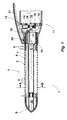
- a brush attachment 1 for a warm air handheld device, not shown for styling comprises a brush section 2 which is round in cross section is trained.
- the brush section 2 is by an outer housing part serving outer cylindrical tube 3 formed in the at intervals Openings 4 are introduced.
- Inside the outer tube 3 is a Bristle holder 5 arranged rotatably with respect to the outer tube 3 stored.
- Radially surrounding the bristle holder 5 are rows of bristles 6 as Bristle arrangements are provided, each consisting of a bristle strip 7 and there are bristles 8.
- Figure 1 is the overview just a row of bristles with only, for example, on the bristle rail 7 arranged bristles 8 shown.
- Each row of bristles is 6 articulated with its bristle rail 7 on the bristle holder 5.
- the individual lots 8 of a row of bristles 6 pass through openings 4 of the outer tube 3 through the outer tube 3.
- the front tip of the outer tube 3 is through a front rounded plug 9 closed.
- the plug 9 carries an axially Socket 10, in which the bristle holder 5 is mounted on the front.
- the brush section 2 borders on one Coupling section 11, the diameter of which compared to that of Brush section 2 is enlarged.
- the coupling section 11 ends at the end in an adapter 12 designed as a sleeve, with which the brush attachment 1 to a warm air handheld device, not shown in the figures is attachable.
- the actuator 13 includes a as Tappet-shaped actuator 14, which is radial to the axis of rotation 15 of the bristle holder 5 is movably mounted according to the direction of the arrow is.
- the actuator 14 is supported on the underside on a compression spring 16 from, so that this against the force of the compression spring 16 to the axis of rotation 15 of the bristle holder 5 is movable.
- the actuator 14 With the actuator 14 in Standing in engagement is a transverse to the axis of rotation 15 of the bristle holder 5 and arranged transversely to the direction of actuation of the actuator 14 as Coupling serving one-armed lever 17 is provided.
- the lever 17 carries at its end a pin 18 which is rotatable in an annular body 19, which in turn is screwed to the coupling section 11, mounted is.
- the other end of the lever 17 engages with another pin 20 into a receptacle assigned to the bristle holder 5.
- the actuator 14 is actuated by an operating lever 21, the is pivotally hinged on the outside of the brush attachment 1.
- the pivot axis of the operating lever 21 is designated by the reference symbol 22.
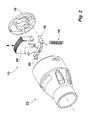
- the coupling section is one further brush attachment 23, not shown in detail.
- the brush attachment 23 corresponds to the brush attachment 1 in FIG. 1; therefore are Identical elements marked with the same reference symbols.
- FIG. 3 shows the brush attachment 23 with the actuated and thus in moved the coupling section 11 of the brush attachment 23 into it Button 24. If button 24 is released, it is replaced by the button in the Compression spring 16 stored energy out of the brush attachment 23 moves, whereby the lever 17 is pivoted about its pin 18 and by rotating the pin 20 of the bristle holder 5 by one certain angular amount is rotated back. The swiveling on the bristle holder 5 arranged rows of bristles 6 are in this Movement pushed out of the outer tube 3.
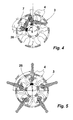
- FIG. 4 The cross section shown in FIG. 4 through the brush section 2 shows the bristle holder 5 with two rows of bristles 6 used by way of example, the bristle strips 7 pivotable in corresponding receptacles 26 of the Bristle holder 5 are articulated.
- Figure 4 is a portion of the bristle holder 5 marked in black.
- the actuating device shown in the figures affects one of the warm air handheld device escaping warm air flow is only insignificant.
- the order the actuator 13 within the airflow ensures the compact design of the brush attachments shown in the figures.
Abstract
Description
Die Erfindung betrifft einen Bürstenaufsatz für ein Warmlufthandgerät zum Frisieren, beispielsweise einen Haartrockner, insbesondere einen solchen umfassend einen Bürstenabschnitt mit mehreren auf einem gegenüber einen äußeren Gehäuseteil axial drehbaren Borstenhalter angeordneten Borstenanordnungen, umfassend ferner eine Einrichtung zum Betätigen des Borstenhalters zum Ein- bzw. Ausziehen der Borstenanordnungen sowie einen Kupplungsabschnitt mit Mitteln zum Anbringen des Bürstenaufsatzes an einem Warmlufthandgerät.The invention relates to a brush attachment for a warm air handheld device for Hairstyles, for example a hair dryer, especially one comprising a brush section with several on one opposite arranged an outer housing part axially rotatable bristle holder Bristle arrangements, further comprising a device for actuation of the bristle holder for pulling the bristle arrangements in and out and a coupling section with means for attaching the brush attachment on a warm air hand device.
Derartige Bürstenaufsätze sind üblicherweise als Rundbürsten ausgebildet, wobei die Borsten in einzelnen Borstenreihen als Borstenanordnung angeordnet und in einem gegenüber einem als äußeres Gehäuseteil dienenden äußeren Rohr drehbar angeordneten Borstenhalter gelagert sind. Eine Betätigungseinrichtung ist dergestalt mit dem Borstenhalter kinematisch verbunden, daß eine Betätigung des Betätigungsgliedes in einer Drehbewegung des Borstenhalters resultiert, so daß die Borsten in ihrer einen Stellung in das äußere Rohr eingezogen sind. Rundbürsten mit einziehbaren Borsten bzw. Borstenanordnungen werden eingesetzt, um zunächst eine Locke auszubilden und anschließend die noch warme Locke zur Erhöhung der Spannkraft freigeben zu können.Such brush attachments are usually designed as round brushes, the bristles in individual rows of bristles as a bristle arrangement arranged and in a serving as an outer housing part outer tube rotatably arranged bristle holder are mounted. An actuating device is kinematic with the bristle holder connected that an actuation of the actuator in a Rotational movement of the bristle holder results, so that the bristles in their a position in the outer tube. Round brushes with retractable Bristles or bristle arrangements are used to initially form a curl and then the still warm curl to release to increase the clamping force.
Als Betätigungseinrichtung kann bei einer solchen vorbekannten Rundbürste an der Spitze des Bürstenaufsatzes ein Druckmechanismus vorgesehen sein, der axial mit der Längsachse des Borstenhalters fluchtend angeordnet ist. Mit dem Betätigungsglied dieser Betätigungseinrichtung wird eine translatorische Bewegung bezogen auf die Drehachse des Borstenhalters zum Einziehen der Borsten ausgeübt, welche translatorische Bewegung über einen Gewindetrieb in eine rotatorische Bewegung des Borstenhalters umgesetzt wird. Es sind weitere Rundbürsten mit einziehbaren Borsten bekannt geworden, an deren Spitze ein Drehmechanismus angeordnet ist, so daß durch Drehen der vorderen Spitze des Bürstenaufsatzes die Borsten ein- bzw. ausziehbar sind. In such a previously known round brush can be used as an actuating device a pressure mechanism is provided at the tip of the brush attachment be axially aligned with the longitudinal axis of the bristle holder is arranged. With the actuator of this actuator becomes a translational movement related to the axis of rotation of the bristle holder exercised to retract the bristles, which translational Movement via a screw drive in a rotary movement of the Bristle holder is implemented. There are other round brushes with retractable Bristles become known, at the tip of a rotating mechanism is arranged so that by rotating the front tip of the brush attachment the bristles are retractable or extractable.
Ein solcher Bürstenaufsatz umfaßt an seinem der Betätigungseinrichtung gegenüber liegenden Ende einen Kupplungsabschnitt mit geeigneten Mitteln zum Anbringen desselben an einem Warmlufthandgerät, welche Verbindungsmittel beispielsweise bajonettartig ausgebildet sein können. Das Innere des Bürstenaufsatzes ist ausgestaltet, damit der von dem Warmlufthandgerät ausgeblasene warme Luftstrom in den Bürstenaufsatz hinein und durch umfänglich angeordnete Öffnungen herausgeblasen werden kann.Such a brush attachment comprises on its the actuating device opposite end a coupling section with suitable Means for attaching the same to a handheld warm air device, which Connection means can be designed, for example, bayonet-like. The interior of the brush attachment is designed so that the Warm air hand device blown out warm air flow in the brush attachment blown in and out through circumferentially arranged openings can be.
Nachteilig ist bei diesen vorbekannten Bürstenaufsätzen, daß ein mit einem solchen Bürstenaufsatz ausgerüstetes Warmlufthandgerät als sogenannter Hair-Curler nur mit zwei Händen bedient werden kann. Mit der einen Hand muß das Warmlufthandgerät gehalten und bedient werden; mit der anderen Hand muß der Bürstenaufsatz betätigt werden, wenn die Borstenanordnung zum Freigeben einer Locke eingezogen werden soll.The disadvantage of these known brush attachments is that one with a such a brush attachment equipped hot air handheld device as a so-called Hair curlers can only be operated with two hands. With the the handheld warm air device must be held and operated; the brush attachment must be operated with the other hand when the Bristle arrangement to release a curl to be drawn.
Ausgehend von diesem diskutierten Stand der Technik liegt der Erfindung daher die Aufgabe zugrunde einen gattungsgemäßen eingangs genannten Bürstenaufsatz für ein Warmlufthandgerät dergestalt weiterzubilden, daß ein mit einem solchen Bürstenaufsatz ausgerüstetes Warmlufthandgerät einhändig bedient werden kann.The invention lies on the basis of this prior art discussed therefore the task of a generic mentioned above To further develop the brush attachment for a warm air handheld device, that a hot air handheld device equipped with such a brush attachment can be operated with one hand.
Diese Aufgabe wird erfindungsgemäß dadurch gelöst, daß die Betätigungseinrichtung im Bereich des Kupplungsabschnittes des Bürstenaufsatzes angeordnet ist und daß die Betätigungseinrichtung über einen radial zur Drehachse des Borstenhalters bewegbares Betätigungsglied verfügt, das an einem mit dem Borstenhalter im Eingriff stehenden Kupplungsstück zum Übertragen der radial zur Drehachse des Borstenhalters gerichteten Bewegung des Betätigungsgliedes auf den drehbaren Borstenhalter angreift.This object is achieved in that the actuator in the area of the coupling section of the brush attachment is arranged and that the actuator via a radial has an actuating element which is movable relative to the axis of rotation of the bristle holder, that on a coupling piece engaged with the bristle holder for transferring the radial to the axis of rotation of the bristle holder directed movement of the actuator on the rotatable bristle holder attacks.
Bei dem erfindungsgemäßen Bürstenaufsatz ist vorgesehen, daß die Betätigungseinrichtung im Bereich des Kupplungsabschnittes des Bürstenaufsatzes und somit unmittelbar im Bereich des Warmlufthandgerätes vorgesehen ist. Die Betätigungseinrichtung ist daher ohne weiteres mit derjenigen Hand ergreif- und bedienbar, mit der das Warmlufthandgerät gehalten wird. Die Betätigungseinrichtung selbst ist dergestalt ausgebildet, daß diese über ein radial zur Drehachse des Borstenhalters bewegbares Betätigungsglied umfaßt, das an einem mit dem Borstenhalter im Eingriff stehenden Kupplungsstück zum Übertragen der radial zur Drehachse des Borstenhalters gerichteten Bewegung des Betätigungsgliedes auf dem drehbaren Borstenhalter angreift. Infolge dieser Ausgestaltung des Betätigungsgliedes kann eine Betätigung des Borstenhalters zum Ein- bzw. Ausziehen der Borsten durch eine Druckbewegung, beispielsweise mit dem Daumen ausgeführt gegen das ohnehin umgriffene Gehäuse des Warmlufthandgerätes erfolgen. Dabei ist vorgesehen, daß die Druckbetätigung zweckmäßigerweise gegen die Kraft eines Federelementes erfolgt, so daß eine Rückstellung der Betätigungseinrichtung in die Ausgangsposition, bei der die Borsten ausgestellt sind, selbsttätig erfolgt.In the brush attachment according to the invention it is provided that the actuating device in the area of the coupling section of the brush attachment and thus directly in the area of the warm air handheld device is provided. The actuator is therefore easily with graspable and operable with the hand with which the warm air hand device is held. The actuating device itself is designed in such a way that this can be moved radially to the axis of rotation of the bristle holder Actuator includes, the one with the bristle holder in Engaging coupling piece for transmitting the radial to the axis of rotation the bristle holder directed movement of the actuator attacks on the rotatable bristle holder. As a result of this configuration of the actuating element, actuation of the bristle holder for or pulling out the bristles by a pressure movement, for example executed with the thumb against the already encompassed housing of the Warm air handheld device. It is provided that the pressure actuation expediently takes place against the force of a spring element, so that the actuator is reset to the starting position, at which the bristles are issued takes place automatically.
In einer zweckmäßigen Ausgestaltung der Erfindung ist vorgesehen, daß das Kupplungsstück der Betätigungseinrichtung ein quer zur Betätigungsrichtung des Betätigungsgliedes sowie quer zur Drehachse des Borstenhalters liegender Hebel ist. Dieser Hebel ist schwenkbar gehäuseseitig gelagert und kann beispielsweise als einarmiger oder auch als zweiarmiger Hebel ausgebildet sein. Durch diesen Hebel erfolgt eine Umsetzung der radial zur Drehachse des Borstenhalters vorgesehenen Betätigungsbewegung in eine rotatorische Bewegung des Borstenhalters. Um die Hebelwirkung des Hebelarmes günstig auszugestalten ist es zweckmäßig, diesen exzentrisch zur Drehachse des Borstenhalters anzuordnen, da auf diese Weise der zur Verfügung stehende Querschnitt des Bürstenaufsatzes im Bereich seines Kupplungsabschnittes weitestgehend ausgenutzt werden kann.In an expedient embodiment of the invention it is provided that the coupling piece of the actuator a transversely to the direction of actuation the actuator and transverse to the axis of rotation of the bristle holder lying lever. This lever is pivotable on the housing side stored and can, for example, as a one-armed or as a two-armed Lever be trained. This lever is used for implementation the actuation movement provided radially to the axis of rotation of the bristle holder in a rotational movement of the bristle holder. To leverage to design the lever arm cheaply, it is appropriate arrange this eccentrically to the axis of rotation of the bristle holder, because on this way the available cross section of the brush attachment extensively used in the area of its coupling section can be.
Zweckmäßig ist die Ausbildung eines einarmigen Hebels des Kupplungsstücks, dessen eines Ende ortsfest bezüglich der Drehbewegung des Borstenhalters gelagert ist und dessen freies, bewegbares Ende mit dem Borstenhalter im Eingriff steht, wobei das Betätigungsglied zwischen diesen beiden Hebelenden an dem Hebel angreift. Die Bestimmung des Angriffspunktes der Betätigungseinrichtung an dem Hebel ist abhängig von dem gewünschten Bewegungsbetrag der Betätigungseinrichtung und dem vorgesehenen Betätigungsdruck zum Ausüben eines Borsteneinzuges. The formation of a one-armed lever of the coupling piece is expedient, one end of which is stationary with respect to the rotational movement of the Bristle holder is mounted and the free, movable end with the Bristle holder is engaged, the actuator between them attacks both lever ends on the lever. The determination of the point of attack the actuator on the lever depends on the desired amount of movement of the actuator and the provided actuating pressure for exerting a bristle retraction.
Der erfindungsgemäße Bürstenaufsatz kann ausgebildet sein, daß das Betätigungsglied benutzerseitig unmittelbar zu betätigen ist oder daß dieses als Stößel ausgebildet ist, der durch einen am Gehäuse des Bürstenaufsatzes angelenkten Hebel betätigbar ist.The brush attachment according to the invention can be designed so that the Actuator to be operated directly by the user or that this is designed as a plunger, which by a on the housing of the brush attachment hinged lever is actuated.
Weitere Vorteile und Ausgestaltungen der Erfindung sind Bestandteil von Unteransprüchen sowie der nachfolgenden Beschreibung eines Ausführungsbeispieles unter Bezugnahme auf die beigefügten Figuren. Es zeigen:
- Fig. 1:
- einen Querschnitt durch einen Büstenaufsatz für ein Warmlufthandgerät zum Frisieren,
- Fig. 2:
- eine dreidimensionale Ansicht nach Art einer Explosionsdarstellung der wesentlichen Elemente einer Betätigungseinrichtung eines weiteren Bürstenaufsatzes,
- Fig. 3:
- eine dreidimensionale Einsicht in den hinteren Bereich des
Bürstenaufsatzes der
Figur 2, - Fig. 4:
- einen schematisierten Querschnitt durch den Bürstenaufsatz der Figur 1 entlang der Linie A-B mit eingezogenen Borsten und
- Fig. 5:
- einen schematisierten Querschnitt durch den Bürstenaufsatz der Figur 1 entlang der Linie A-B mit ausgestellten Borsten.
- Fig. 1:
- 2 shows a cross section through a brush attachment for a hot air hand device for styling,
- Fig. 2:
- 3 shows a three-dimensional view in the manner of an exploded view of the essential elements of an actuating device of a further brush attachment,
- Fig. 3:
- 3 shows a three-dimensional view of the rear area of the brush attachment of FIG. 2,
- Fig. 4:
- a schematic cross section through the brush attachment of Figure 1 along line AB with retracted bristles and
- Fig. 5:
- a schematic cross section through the brush attachment of Figure 1 along the line AB with flared bristles.
Ein Bürstenaufsatz 1 für ein nicht näher dargestelltes Warmlufthandgerät
zum Frisieren umfaßt einen Bürstenabschnitt 2, der im Querschnitt rund
ausgebildet ist. Der Bürstenabschnitt 2 wird durch ein als äußeres Gehäuseteil
dienendes äußeres zylindrisches Rohr 3 gebildet, in das in Abständen
Öffnungen 4 eingebracht sind. Innerhalb des äußeren Rohrs 3 ist ein
drehbar bezüglich des äußeren Rohres 3 angeordneter Borstenhalter 5
gelagert. Radial den Borstenhalter 5 umgebend sind Borstenreihen 6 als
Borstenanordnungen vorgesehen, die aus jeweils einer Borstenleiste 7
und darauf befindlichen Borsten 8 bestehen. In der Figur 1 ist der Übersicht
halber lediglich eine Borstenreihe mit nur beispielsweise auf der Borstenschiene
7 angeordneten Borsten 8 gezeigt. Jede Borstenreihe 6 ist
mit ihrer Borstenschiene 7 schwenkbar an dem Borstenhalter 5 angelenkt.
Die einzelnen Bosten 8 einer Borstenreihe 6 treten durch Öffnungen 4 des
äußeren Rohres 3 durch das äußere Rohr 3 hindurch.A brush attachment 1 for a warm air handheld device, not shown
for styling comprises a
Die vordere Spitzes des äußeren Rohres 3 ist durch einen vorderseitig
gerundeten Stopfen 9 verschlossen. Der Stopfen 9 trägt achsial eine
Buchse 10, in der der Borstenhalter 5 vorderseitig gelagert ist.The front tip of the
Dem Stopfen 9 gegenüberliegend grenzt der Bürstenabschnitt 2 an einen
Kupplungsabschnitt 11, dessen Durchmesser gegenüber demjenigen des
Bürstenabschnittes 2 vergrößert ist. Der Kupplungsabschnitt 11 endet
endseitig in einem als Muffe ausgebildeten Adapter 12, mit dem der Bürstenaufsatz
1 auf ein in den Figuren nicht dargestelltes Warmlufthandgerät
aufsteckbar ist.Opposite the
Im Bereich des Kupplungsabschnittes 11 ist eine Betätigungseinrichtung
13 zum Betätigen des Borstenhalters 5 zum Ein- bzw. Ausziehen der Borstenreihen
6 vorgesehen. Die Betätigungseinrichtung 13 umfaßt ein als
Stößel ausgebildetes Betätigungsglied 14, welches radial zur Drehachse
15 des Borstenhalters 5 entsprechend der Pfeilrichtung bewegbar gelagert
ist. Das Betätigungsglied 14 stützt sich unterseitig auf einer Druckfeder
16 ab, so daß dieses gegen die Kraft der Druckfeder 16 zur Drehachse
15 des Borstenhalters 5 bewegbar ist. Mit dem Betätigungsglied 14 im
Eingriff stehend ist ein quer zur Drehachse 15 des Borstenhalters 5 sowie
quer zur Betätigungsrichtung des Betätigungsgliedes 14 angeordneter, als
Kupplungsstück dienender einarmiger Hebel 17 vorgesehen. Der Hebel
17 trägt an seinem Ende einen Zapfen 18, der drehbar in einem Ringkörper
19, der wiederum mit dem Kupplungsabschnitt 11 verschraubt ist, gelagert
ist. Das andere Ende des Hebels 17 greift mit einem weiteren Zapfen
20 in eine dem Borstenhalter 5 zugeordnete Aufnahme ein. Zwischen
den beiden Zapfen 18, 20 greift das Betätigungsglied 14 an dem Hebel 17
an.In the area of the
Das Betätigungsglied 14 ist durch einen Bedienhebel 21 betätigbar, der
außenseitig an dem Bürstenaufsatz 1 schwenkbar angelenkt ist. Die
Schwenkachse des Bedienhebels 21 ist mit dem Bezugszeichen 22 bezeichnet. The
In der Explosionsdarstellung der Figur 2 ist der Kupplungsabschnitt eines
weiteren, nicht näher dargestellten Bürstenaufsatzes 23 gezeigt. Der Bürstenaufsatz
23 entspricht dem Bürstenaufsatz 1 der Figur 1; daher sind
gleiche Elemente mit gleichen Bezugszeichen gekennzeichnet. Einziger
Unterschied des Bürstenaufsatzes 23 zu den Bürstenaufsatz 1 besteht
darin, daß als Betätigungsglied nicht ein Stößel sondern ein Taster 24
eingesetzt ist, der unmittelbar bedient wird.In the exploded view of Figure 2, the coupling section is one
Besonders deutlich treten aus dieser Figur die für die Bedieneinrichtung
13 eingesetzten Elemente, nämlich der Taster 24, der Hebel 17 und der
gehäuseseitig befestigbare Ringkörper 19 in Erscheinung. Entsprechende
Pfeildarstellungen spiegeln die mögliche Bewegung und den entsprechenden
Bewegungsverlauf wider. Aus der in Figur 3 gezeigten Einsicht in
den Bürstenaufsatz 23 wird das Zusammenspiel der Einzelelemente, dem
Taster 24, dem Hebel 17, dem Ringkörper 19 und dem Borstenhalter 5
deutlich. Der Hebel 17 ist mit seinem Zapfen 18 in dem Ringkörper 19
ortsfest, jedoch drehbar gelagert. Das andere Ende des Hebels 17 greift
mit seinem Zapfen 20 in eine am Borstenhalter 5 angeformte Aufnahme
25 ein. Da auch der Taster 24 zum Betätigen des Hebels 17 vorgesehen
ist, wird deutlich, daß bei einer radialen Bewegung des Tasters 24 diese
Bewegungen eine rotatorische Bewegung des Borstenhalters 5 zur Folge
hat. Figur 3 zeigt den Bürstenaufsatz 23 mit dem betätigten und somit in
den Kupplungsabschnitt 11 des Bürstenaufsatzes 23 hinein bewegten
Taster 24. Wird der Taster 24 losgelassen, wird dieser durch die in der
Druckfeder 16 gespeicherte Energie aus dem Bürstenaufsatz 23 heraus
bewegt, wodurch der Hebel 17 um seinen Zapfen 18 verschwenkt wird
und durch die Drehmitnahme des Zapfens 20 der Borstenhalter 5 um einen
bestimmten Winkelbetrag zurück gedreht wird. Die schwenkbar an
dem Borstenhalter 5 angeordneten Borstenreihen 6 werden bei dieser
Bewegung aus dem äußeren Rohr 3 ausgeschoben.The figures for the operating device emerge particularly clearly from this figure
13 used elements, namely the
Der in Figur 4 gezeigte Querschnitt durch den Bürstenabschnitt 2 zeigt
den Borstenhalter 5 mit zwei beispielhaft eingesetzten Borstenreihen 6,
deren Borstenleisten 7 schwenkbar in entsprechenden Aufnahmen 26 des
Borstenhalters 5 angelenkt sind. In Figur 4 ist ein Abschnitt des Borstenhalters
5 schwarz markiert. Bei einem Loslassen des Bedienelementes 14
wird der Borstenhalter 5 entsprechend der Pfeilrichtung in Figur 4 bewegt,
bis der Bürstenaufsatz 1 mit den ausgezogenen Borsten 8 seine in Figur 5
gezeigte Stellung inne hat.The cross section shown in FIG. 4 through the
Die in den Figuren gezeigte Betätigungseinrichtung, wie sich dies insbesondere
aus Figur 3 ergibt, beeinträchtigt einen von dem Warmlufthandgerät
austretenden warmen Luftstrom nur unwesentlich. Die Anordnung
der Betätigungseinrichtung 13 innerhalb des Luftstromes gewährleistet die
kompakte Bauweise der in den Figuren gezeigten Bürstenaufsätze. The actuating device shown in the figures, as can be seen in particular
from Figure 3 affects one of the warm air handheld device
escaping warm air flow is only insignificant. The order
the
- 11
- Bürstenaufsatzbrush tool
- 22
- Bürstenabschnittbrush section
- 33
- Äußeres RohrOuter tube
- 44
- Öffnungopening
- 55
- Borstenhalterbristle holder
- 66
- Borstenanordnungbristle arrangement
- 77
- Borstenleistebristle strip
- 88th
- Borstebristle
- 99
- StopfenPlug
- 1010
- BuchseRifle
- 1111
- Kupplungsabschnittcoupling section
- 1212
- Adapteradapter
- 1313
- Betätigungseinrichtungactuator
- 1414
- Betätigungsgliedactuator
- 1515
- Drehachseaxis of rotation
- 1616
- Druckfedercompression spring
- 1717
- Hebellever
- 1818
- Zapfenspigot
- 1919
- Ringkörperring body
- 2020
- Zapfenspigot
- 2121
- Bedienhebeloperating lever
- 2222
- Schwenkachseswivel axis
- 2323
- Bürstenaufsatzbrush tool
- 2424
- Tasterbutton
- 2525
- Aufnahme zur DrehmitnahmeRecording for the take along
- 2626
- Aufnahmeadmission
Claims (6)
- Brush attachment for a hand-held hot-air appliance and comprising a brush portion having a plurality of bristle elements (6) arranged on a brush holder (5) which is axially rotatable relative to an outer housing portion (3), said brush attachment further comprising a device (13) for actuating the bristle holder (5) to withdraw or extend the bristle elements (6), as well as a coupling portion (11) having means for attaching the brush attachment (1, 23) to a hand-held hot-air appliance, characterised in that the actuating device (13) is disposed in the region of the coupling portion (11) of the brush attachment (1, 23) and in that the actuating device (13) has an actuation member (14, 24) which can be moved radially with respect to the rotational axis (15) of the bristle holder (5) and which acts upon a coupling member (17), which engages with the bristle holder (5), to transmit the movement of the actuation member (14,24) to the rotatable bristle holder, said movement being directed radially with respect to the rotational axis (15) of the bristle holder (5).
- Brush attachment according to claim 1, characterised in that the coupling member is a lever (17) which lies transversely with respect to the direction of actuation of the actuation member (14, 24) as well as transversely with respect to the longitudinal axis of the brush attachment (1, 23), the actuation member (14, 24) engaging on the one arm of said lever.
- Brush attachment according to claim 2, characterised in that the lever (17) is configured as a one-armed lever, one end of which is mounted stationary with respect to the rotational movement of the bristle holder (5), and the free moveable end of which engages with the bristle holder (5), the actuation member (14, 29) acting upon the lever (17) between these two lever ends.
- Brush attachment according to one of claims 1 to 3, characterised in that the lever (17) is mounted on the housing side in an annular body (19) which can be inserted into the outer housing portion of the brush attachment (1, 23) from the direction of the coupling region (11).
- Brush attachment according to one of claims 1 to 4, characterised in that the actuation member is a plunger (14) which can be actuated by means of a lever (21) coupled to the housing of the brush attachment (1).
- Brush attachment according to one of claims 1 to 5, characterised in that the actuation member (14, 24) can be actuated during a movement towards the rotational axis (15) of the bristle holder (5) against the force of a spring element (16).
Applications Claiming Priority (3)
| Application Number | Priority Date | Filing Date | Title |
|---|---|---|---|
| DE29915051U DE29915051U1 (en) | 1999-08-27 | 1999-08-27 | Brush attachment for a warm air hand device |
| DE29915051U | 1999-08-27 | ||
| PCT/EP2000/008012 WO2001015568A1 (en) | 1999-08-27 | 2000-08-17 | Brush attachment for a hand-held device diffusing hot air |
Publications (2)
| Publication Number | Publication Date |
|---|---|
| EP1123019A1 EP1123019A1 (en) | 2001-08-16 |
| EP1123019B1 true EP1123019B1 (en) | 2003-04-16 |
Family
ID=8078105
Family Applications (1)
| Application Number | Title | Priority Date | Filing Date |
|---|---|---|---|
| EP00954634A Expired - Lifetime EP1123019B1 (en) | 1999-08-27 | 2000-08-17 | Brush attachment for a hand-held device diffusing hot air |
Country Status (11)
| Country | Link |
|---|---|
| US (1) | US6532968B1 (en) |
| EP (1) | EP1123019B1 (en) |
| JP (1) | JP3980882B2 (en) |
| CN (1) | CN1147256C (en) |
| AT (1) | ATE237249T1 (en) |
| AU (1) | AU769711B2 (en) |
| DE (2) | DE29915051U1 (en) |
| ES (1) | ES2191634T3 (en) |
| HK (1) | HK1040478B (en) |
| TW (1) | TWI246891B (en) |
| WO (1) | WO2001015568A1 (en) |
Cited By (3)
| Publication number | Priority date | Publication date | Assignee | Title |
|---|---|---|---|---|
| DE202010008499U1 (en) | 2010-09-09 | 2011-12-13 | Wik Far East Ltd. | Hairbrush with retractable bristles |
| US10660418B2 (en) | 2017-07-14 | 2020-05-26 | Spectrum Brands, Inc. | Air-moving appliance including an attachment |
| US10835007B2 (en) | 2017-07-14 | 2020-11-17 | Spectrum Brands, Inc. | Hair dryer |
Families Citing this family (12)
| Publication number | Priority date | Publication date | Assignee | Title |
|---|---|---|---|---|
| AR044726A1 (en) | 2002-03-04 | 2005-10-05 | Beatriz Monica Feldman | MODELING DEVICE IN HAIR DRYERS |
| US20090260651A1 (en) * | 2005-08-30 | 2009-10-22 | Dickson Industrial Co., Ltd | Hair styling apparatus with retractable styling heads |
| WO2009086063A1 (en) * | 2007-12-19 | 2009-07-09 | Conair Corporation | Convertible hair appliance |
| ATE507038T1 (en) * | 2008-02-28 | 2011-05-15 | Procter & Gamble | DEVICE FOR CUTTING SPLIT TENDS OF HAIR |
| KR200456395Y1 (en) | 2011-08-01 | 2011-10-27 | 조성찬 | hair iron having brush |
| US9217221B2 (en) * | 2011-11-21 | 2015-12-22 | Michael W. Catoe | Pocket inverter |
| KR101326656B1 (en) | 2012-04-06 | 2013-11-07 | 최진호 | A curling iron appearing and disappearing the teeth of a comb |
| KR101222692B1 (en) * | 2012-09-19 | 2013-01-16 | 조성찬 | Hair iron having brush |
| DE102013211192B4 (en) | 2013-06-14 | 2020-01-16 | BSH Hausgeräte GmbH | Attachment for a hair care device and hair care device |
| DE102015202202A1 (en) | 2015-02-06 | 2016-08-11 | BSH Bosch und Siemens Hausgeräte GmbH | Hair care device |
| US10973298B2 (en) * | 2017-09-12 | 2021-04-13 | The Beachwaver Co. | Digitally controlled hairdryer |
| CN114098258A (en) * | 2021-11-22 | 2022-03-01 | 惠州市文德智能科技有限公司 | Shaping comb |
Family Cites Families (8)
| Publication number | Priority date | Publication date | Assignee | Title |
|---|---|---|---|---|
| DE2944050B1 (en) * | 1979-10-31 | 1981-04-30 | Icomag Trust Reg., Vaduz | curler |
| DE3204469A1 (en) * | 1982-02-09 | 1983-09-01 | WIK Elektro-Hausgeräte-Vertriebsgesellschaft mbH & Co Produktionskommanditgesellschaft, 4300 Essen | HAIRDRESSER FOR STYLING, WINDING AND DRYING HAIR |
| LU85452A1 (en) | 1984-07-06 | 1986-02-12 | Faco Sa | BLOWER BRUSH FOR WAVY HAIR |
| DE8437528U1 (en) | 1984-12-21 | 1985-03-28 | Kiefner, Georg, 5000 Köln | HAIRBRUSH |
| DE3837297A1 (en) | 1988-11-03 | 1990-05-10 | Wella Ag | HOT AIR CURL ROD DEVICE |
| US5212366A (en) * | 1990-10-24 | 1993-05-18 | China Pacific Trade Ltd. | Handheld hair care appliance with adjustable diameter barrel providing heated airflow |
| US5091630A (en) * | 1990-11-05 | 1992-02-25 | Zoran Djuric | Hair curling apparatus mounted to a hair dryer outlet conduit with an adapter sleeve arrangement rotatably mounted and rotated by heated air flow |
| US6070594A (en) * | 1998-02-25 | 2000-06-06 | Arich, Inc. | Brush with retractable bristles |
-
1999
- 1999-08-27 DE DE29915051U patent/DE29915051U1/en not_active Expired - Lifetime
-
2000
- 2000-08-04 TW TW089115680A patent/TWI246891B/en not_active IP Right Cessation
- 2000-08-17 CN CNB00801874XA patent/CN1147256C/en not_active Expired - Fee Related
- 2000-08-17 US US09/830,852 patent/US6532968B1/en not_active Expired - Lifetime
- 2000-08-17 JP JP2001519793A patent/JP3980882B2/en not_active Expired - Fee Related
- 2000-08-17 WO PCT/EP2000/008012 patent/WO2001015568A1/en active IP Right Grant
- 2000-08-17 AT AT00954634T patent/ATE237249T1/en not_active IP Right Cessation
- 2000-08-17 ES ES00954634T patent/ES2191634T3/en not_active Expired - Lifetime
- 2000-08-17 DE DE50001782T patent/DE50001782D1/en not_active Expired - Lifetime
- 2000-08-17 AU AU67022/00A patent/AU769711B2/en not_active Ceased
- 2000-08-17 EP EP00954634A patent/EP1123019B1/en not_active Expired - Lifetime
-
2002
- 2002-02-09 HK HK02101046.0A patent/HK1040478B/en not_active IP Right Cessation
Cited By (7)
| Publication number | Priority date | Publication date | Assignee | Title |
|---|---|---|---|---|
| DE202010008499U1 (en) | 2010-09-09 | 2011-12-13 | Wik Far East Ltd. | Hairbrush with retractable bristles |
| EP2428132A1 (en) | 2010-09-09 | 2012-03-14 | WIK Far East Ltd | Hair brush with retractable bristles |
| US10660418B2 (en) | 2017-07-14 | 2020-05-26 | Spectrum Brands, Inc. | Air-moving appliance including an attachment |
| US10835007B2 (en) | 2017-07-14 | 2020-11-17 | Spectrum Brands, Inc. | Hair dryer |
| US11311090B2 (en) | 2017-07-14 | 2022-04-26 | Spectrum Brands, Inc. | Hair dryer |
| US11330884B2 (en) | 2017-07-14 | 2022-05-17 | Spectrum Brands, Inc. | Air-moving appliance including an attachment |
| US11877638B2 (en) | 2017-07-14 | 2024-01-23 | Spectrum Brands, Inc. | Air-moving appliance including an attachment |
Also Published As
| Publication number | Publication date |
|---|---|
| TWI246891B (en) | 2006-01-11 |
| CN1147256C (en) | 2004-04-28 |
| HK1040478B (en) | 2004-01-02 |
| US6532968B1 (en) | 2003-03-18 |
| CN1321072A (en) | 2001-11-07 |
| ATE237249T1 (en) | 2003-05-15 |
| ES2191634T3 (en) | 2003-09-16 |
| WO2001015568A1 (en) | 2001-03-08 |
| AU6702200A (en) | 2001-03-26 |
| DE50001782D1 (en) | 2003-05-22 |
| DE29915051U1 (en) | 1999-12-09 |
| AU769711B2 (en) | 2004-01-29 |
| EP1123019A1 (en) | 2001-08-16 |
| JP2003508100A (en) | 2003-03-04 |
| JP3980882B2 (en) | 2007-09-26 |
| HK1040478A1 (en) | 2002-06-14 |
Similar Documents
| Publication | Publication Date | Title |
|---|---|---|
| EP1123019B1 (en) | Brush attachment for a hand-held device diffusing hot air | |
| EP2428132B1 (en) | Hair brush with retractable bristles | |
| DE10005584A1 (en) | Biopsy forceps for endoscope has knob provided to front end of operation section and that is operated to rotate sheath which does not twist over its total length when driven | |
| EP2170117B1 (en) | Hair care device | |
| WO2002067748A1 (en) | Vacuum cleaner comprising attachments | |
| DE2944050B1 (en) | curler | |
| DE2406800A1 (en) | CYLINDRICAL HAIR BRUSH | |
| EP1908386B1 (en) | Hand-operated adjustable vacuum nozzle | |
| DE3204469A1 (en) | HAIRDRESSER FOR STYLING, WINDING AND DRYING HAIR | |
| EP0850002B1 (en) | Hair styling and/or drying attachment for blower device | |
| DE19905982C2 (en) | Cytological brush for endoscopes | |
| EP3426168A1 (en) | Hand-operated functional hose instrument | |
| DE19647761C1 (en) | Manual control for endoscope with handle and endoscope tube arrangement | |
| EP0841033A2 (en) | Telescopic vacuum cleaner suction hose | |
| DE4414809C2 (en) | Manual control device for an endoscope | |
| DE4318950C1 (en) | Tissue spreading device | |
| DE3016455C2 (en) | Device for shaping hair curls | |
| DE8206841U1 (en) | Hair curlers for styling hair | |
| EP3793398B1 (en) | Hair clip | |
| EP1177073B1 (en) | Cleaning device for motor vehicles | |
| DE2742626B1 (en) | Hot air hand hairdresser with a handle and a round brush | |
| DE4405922C1 (en) | Housing sleeve for a pen, pencil or crayon | |
| DE102020121196A1 (en) | Surface treatment device with a remote unlocking device for an attachment | |
| DE1022122B (en) | Flat lead twist pin | |
| DE102015201212B4 (en) | Hair curlers |
Legal Events
| Date | Code | Title | Description |
|---|---|---|---|
| PUAI | Public reference made under article 153(3) epc to a published international application that has entered the european phase |
Free format text: ORIGINAL CODE: 0009012 |
|
| 17P | Request for examination filed |
Effective date: 20010302 |
|
| AK | Designated contracting states |
Kind code of ref document: A1 Designated state(s): AT BE CH CY DE DK ES FI FR GB GR IE IT LI LU MC NL PT SE |
|
| AX | Request for extension of the european patent |
Free format text: AL;LT;LV;MK;RO;SI |
|
| GRAH | Despatch of communication of intention to grant a patent |
Free format text: ORIGINAL CODE: EPIDOS IGRA |
|
| GRAH | Despatch of communication of intention to grant a patent |
Free format text: ORIGINAL CODE: EPIDOS IGRA |
|
| GRAA | (expected) grant |
Free format text: ORIGINAL CODE: 0009210 |
|
| AK | Designated contracting states |
Designated state(s): AT BE CH CY DE DK ES FI FR GB GR IE IT LI LU MC NL PT SE |
|
| PG25 | Lapsed in a contracting state [announced via postgrant information from national office to epo] |
Ref country code: FI Free format text: LAPSE BECAUSE OF FAILURE TO SUBMIT A TRANSLATION OF THE DESCRIPTION OR TO PAY THE FEE WITHIN THE PRESCRIBED TIME-LIMIT Effective date: 20030416 Ref country code: DK Free format text: LAPSE BECAUSE OF FAILURE TO SUBMIT A TRANSLATION OF THE DESCRIPTION OR TO PAY THE FEE WITHIN THE PRESCRIBED TIME-LIMIT Effective date: 20030416 Ref country code: IE Free format text: LAPSE BECAUSE OF NON-PAYMENT OF DUE FEES Effective date: 20030416 |
|
| REG | Reference to a national code |
Ref country code: GB Ref legal event code: FG4D Free format text: NOT ENGLISH |
|
| REG | Reference to a national code |
Ref country code: CH Ref legal event code: NV Representative=s name: PA ALDO ROEMPLER Ref country code: CH Ref legal event code: EP |
|
| GBT | Gb: translation of ep patent filed (gb section 77(6)(a)/1977) |
Effective date: 20030416 |
|
| REF | Corresponds to: |
Ref document number: 50001782 Country of ref document: DE Date of ref document: 20030522 Kind code of ref document: P |
|
| REG | Reference to a national code |
Ref country code: IE Ref legal event code: FG4D Free format text: GERMAN |
|
| PG25 | Lapsed in a contracting state [announced via postgrant information from national office to epo] |
Ref country code: PT Free format text: LAPSE BECAUSE OF FAILURE TO SUBMIT A TRANSLATION OF THE DESCRIPTION OR TO PAY THE FEE WITHIN THE PRESCRIBED TIME-LIMIT Effective date: 20030716 Ref country code: GR Free format text: LAPSE BECAUSE OF FAILURE TO SUBMIT A TRANSLATION OF THE DESCRIPTION OR TO PAY THE FEE WITHIN THE PRESCRIBED TIME-LIMIT Effective date: 20030716 |
|
| REG | Reference to a national code |
Ref country code: SE Ref legal event code: TRGR |
|
| PG25 | Lapsed in a contracting state [announced via postgrant information from national office to epo] |
Ref country code: LU Free format text: LAPSE BECAUSE OF NON-PAYMENT OF DUE FEES Effective date: 20030817 Ref country code: CY Free format text: LAPSE BECAUSE OF FAILURE TO SUBMIT A TRANSLATION OF THE DESCRIPTION OR TO PAY THE FEE WITHIN THE PRESCRIBED TIME-LIMIT Effective date: 20030817 Ref country code: AT Free format text: LAPSE BECAUSE OF NON-PAYMENT OF DUE FEES Effective date: 20030817 |
|
| PG25 | Lapsed in a contracting state [announced via postgrant information from national office to epo] |
Ref country code: BE Free format text: LAPSE BECAUSE OF NON-PAYMENT OF DUE FEES Effective date: 20030831 Ref country code: MC Free format text: LAPSE BECAUSE OF NON-PAYMENT OF DUE FEES Effective date: 20030831 |
|
| REG | Reference to a national code |
Ref country code: ES Ref legal event code: FG2A Ref document number: 2191634 Country of ref document: ES Kind code of ref document: T3 |
|
| LTIE | Lt: invalidation of european patent or patent extension |
Effective date: 20030416 |
|
| ET | Fr: translation filed | ||
| REG | Reference to a national code |
Ref country code: IE Ref legal event code: FD4D Ref document number: 1123019E Country of ref document: IE |
|
| PLBE | No opposition filed within time limit |
Free format text: ORIGINAL CODE: 0009261 |
|
| STAA | Information on the status of an ep patent application or granted ep patent |
Free format text: STATUS: NO OPPOSITION FILED WITHIN TIME LIMIT |
|
| BERE | Be: lapsed |
Owner name: *WIK FAR EAST LTD Effective date: 20030831 |
|
| 26N | No opposition filed |
Effective date: 20040119 |
|
| REG | Reference to a national code |
Ref country code: CH Ref legal event code: PCAR Free format text: ALDO ROEMPLER PATENTANWALT;BRENDENWEG 11 POSTFACH 154;9424 RHEINECK (CH) |
|
| PGFP | Annual fee paid to national office [announced via postgrant information from national office to epo] |
Ref country code: NL Payment date: 20080820 Year of fee payment: 9 |
|
| REG | Reference to a national code |
Ref country code: NL Ref legal event code: V1 Effective date: 20100301 |
|
| PG25 | Lapsed in a contracting state [announced via postgrant information from national office to epo] |
Ref country code: NL Free format text: LAPSE BECAUSE OF NON-PAYMENT OF DUE FEES Effective date: 20100301 |
|
| PGFP | Annual fee paid to national office [announced via postgrant information from national office to epo] |
Ref country code: SE Payment date: 20110823 Year of fee payment: 12 |
|
| PGFP | Annual fee paid to national office [announced via postgrant information from national office to epo] |
Ref country code: IT Payment date: 20110825 Year of fee payment: 12 |
|
| REG | Reference to a national code |
Ref country code: SE Ref legal event code: EUG |
|
| PG25 | Lapsed in a contracting state [announced via postgrant information from national office to epo] |
Ref country code: SE Free format text: LAPSE BECAUSE OF NON-PAYMENT OF DUE FEES Effective date: 20120818 |
|
| PG25 | Lapsed in a contracting state [announced via postgrant information from national office to epo] |
Ref country code: IT Free format text: LAPSE BECAUSE OF NON-PAYMENT OF DUE FEES Effective date: 20120817 |
|
| PGFP | Annual fee paid to national office [announced via postgrant information from national office to epo] |
Ref country code: ES Payment date: 20130828 Year of fee payment: 14 Ref country code: CH Payment date: 20130826 Year of fee payment: 14 |
|
| PGFP | Annual fee paid to national office [announced via postgrant information from national office to epo] |
Ref country code: GB Payment date: 20130823 Year of fee payment: 14 |
|
| REG | Reference to a national code |
Ref country code: CH Ref legal event code: PL |
|
| GBPC | Gb: european patent ceased through non-payment of renewal fee |
Effective date: 20140817 |
|
| PG25 | Lapsed in a contracting state [announced via postgrant information from national office to epo] |
Ref country code: LI Free format text: LAPSE BECAUSE OF NON-PAYMENT OF DUE FEES Effective date: 20140831 Ref country code: CH Free format text: LAPSE BECAUSE OF NON-PAYMENT OF DUE FEES Effective date: 20140831 |
|
| PG25 | Lapsed in a contracting state [announced via postgrant information from national office to epo] |
Ref country code: GB Free format text: LAPSE BECAUSE OF NON-PAYMENT OF DUE FEES Effective date: 20140817 |
|
| REG | Reference to a national code |
Ref country code: ES Ref legal event code: FD2A Effective date: 20150925 |
|
| PG25 | Lapsed in a contracting state [announced via postgrant information from national office to epo] |
Ref country code: ES Free format text: LAPSE BECAUSE OF NON-PAYMENT OF DUE FEES Effective date: 20140818 |
|
| REG | Reference to a national code |
Ref country code: FR Ref legal event code: PLFP Year of fee payment: 17 |
|
| REG | Reference to a national code |
Ref country code: FR Ref legal event code: PLFP Year of fee payment: 18 |
|
| PGFP | Annual fee paid to national office [announced via postgrant information from national office to epo] |
Ref country code: FR Payment date: 20170823 Year of fee payment: 18 Ref country code: DE Payment date: 20170710 Year of fee payment: 18 |
|
| REG | Reference to a national code |
Ref country code: DE Ref legal event code: R119 Ref document number: 50001782 Country of ref document: DE |
|
| PG25 | Lapsed in a contracting state [announced via postgrant information from national office to epo] |
Ref country code: DE Free format text: LAPSE BECAUSE OF NON-PAYMENT OF DUE FEES Effective date: 20190301 |
|
| PG25 | Lapsed in a contracting state [announced via postgrant information from national office to epo] |
Ref country code: FR Free format text: LAPSE BECAUSE OF NON-PAYMENT OF DUE FEES Effective date: 20180831 |