EP0841033A2 - Telescopic vacuum cleaner suction hose - Google Patents
Telescopic vacuum cleaner suction hose Download PDFInfo
- Publication number
- EP0841033A2 EP0841033A2 EP97115878A EP97115878A EP0841033A2 EP 0841033 A2 EP0841033 A2 EP 0841033A2 EP 97115878 A EP97115878 A EP 97115878A EP 97115878 A EP97115878 A EP 97115878A EP 0841033 A2 EP0841033 A2 EP 0841033A2
- Authority
- EP
- European Patent Office
- Prior art keywords
- outer tube
- section
- locking
- pipe according
- intake pipe
- Prior art date
- Legal status (The legal status is an assumption and is not a legal conclusion. Google has not performed a legal analysis and makes no representation as to the accuracy of the status listed.)
- Withdrawn
Links
- 239000004033 plastic Substances 0.000 claims description 4
- 239000002184 metal Substances 0.000 claims description 3
- 230000002441 reversible effect Effects 0.000 claims description 2
- 230000013011 mating Effects 0.000 abstract 1
- 230000000694 effects Effects 0.000 description 3
- 230000015572 biosynthetic process Effects 0.000 description 1
- 230000000295 complement effect Effects 0.000 description 1
- 230000008921 facial expression Effects 0.000 description 1
- 238000004519 manufacturing process Methods 0.000 description 1
Images

Classifications
-
- A—HUMAN NECESSITIES
- A47—FURNITURE; DOMESTIC ARTICLES OR APPLIANCES; COFFEE MILLS; SPICE MILLS; SUCTION CLEANERS IN GENERAL
- A47L—DOMESTIC WASHING OR CLEANING; SUCTION CLEANERS IN GENERAL
- A47L9/00—Details or accessories of suction cleaners, e.g. mechanical means for controlling the suction or for effecting pulsating action; Storing devices specially adapted to suction cleaners or parts thereof; Carrying-vehicles specially adapted for suction cleaners
- A47L9/24—Hoses or pipes; Hose or pipe couplings
- A47L9/242—Hose or pipe couplings
- A47L9/244—Hose or pipe couplings for telescopic or extensible hoses or pipes
-
- F—MECHANICAL ENGINEERING; LIGHTING; HEATING; WEAPONS; BLASTING
- F16—ENGINEERING ELEMENTS AND UNITS; GENERAL MEASURES FOR PRODUCING AND MAINTAINING EFFECTIVE FUNCTIONING OF MACHINES OR INSTALLATIONS; THERMAL INSULATION IN GENERAL
- F16L—PIPES; JOINTS OR FITTINGS FOR PIPES; SUPPORTS FOR PIPES, CABLES OR PROTECTIVE TUBING; MEANS FOR THERMAL INSULATION IN GENERAL
- F16L37/00—Couplings of the quick-acting type
- F16L37/08—Couplings of the quick-acting type in which the connection between abutting or axially overlapping ends is maintained by locking members
- F16L37/12—Couplings of the quick-acting type in which the connection between abutting or axially overlapping ends is maintained by locking members using hooks, pawls or other movable or insertable locking members
-
- F—MECHANICAL ENGINEERING; LIGHTING; HEATING; WEAPONS; BLASTING
- F16—ENGINEERING ELEMENTS AND UNITS; GENERAL MEASURES FOR PRODUCING AND MAINTAINING EFFECTIVE FUNCTIONING OF MACHINES OR INSTALLATIONS; THERMAL INSULATION IN GENERAL
- F16B—DEVICES FOR FASTENING OR SECURING CONSTRUCTIONAL ELEMENTS OR MACHINE PARTS TOGETHER, e.g. NAILS, BOLTS, CIRCLIPS, CLAMPS, CLIPS OR WEDGES; JOINTS OR JOINTING
- F16B7/00—Connections of rods or tubes, e.g. of non-circular section, mutually, including resilient connections
- F16B7/10—Telescoping systems
- F16B7/105—Telescoping systems locking in discrete positions, e.g. in extreme extended position
Definitions
- the invention relates to a telescopic suction pipe for Vacuum cleaner, consisting of two slidable Pipes, the inner pipe several in the axial direction has spaced-apart locking recesses into which to lock the pipes to each other by pressing one arranged on the outer tube handling element Locking element is releasably latchable.
- Such a suction pipe is, for example, from DE 195 24 290 C1 known.
- a handling element in the form of a Outer tube attached slider which against the effect a spring can be tensioned.
- the slide be operated so that a free space above Snap element is created, in which this disengage can.
- the invention is therefore based on the problem of a specify telescopic suction tube, which in its Structure is extremely simple at the same time easy handling and ensuring a safe Locking the individual positions.
- the Handling element on the outer tube against the effect of a Restoring force is arranged so that it can be pivoted like a lever, that the locking element arranged on the handling element Operation of the handling element reversible between a locking and a release position is movable.
- the invention therefore proceeds from that in the prior art known way of using sliders and separate Locking elements and makes the advantageous Take advantage of the pivoting bearing of the handling element.
- the Locking element is advantageous directly on the handling element arranged, no longer represents a separate part, which is why, in addition to the simple Advantages that can be swiveled have particular advantages surrender. Because the handling element becomes the simplest pivoted completely while releasing the lock, so that the individual tubes are displaceable against each other, and will by the effect of the restoring force in the locking position when releasing the force to be pivoted brought. In this way, it is extremely simple system that can be handled and manufactured, that no longer has the disadvantages described above.
- the handling element as the Outer tube encompassing more than half the circumference, slotted clamp is formed, the one Encompassing the outer tube, to more than half the extent encompassing area on the outer wall of the outer tube can be put on and carrying the latching element first section and a second section to be operated for pivoting has, the first section being so elastic is formed that when pressing the second section which with respect to the outer wall of the outer tube moved first section generating one Restoring force can be preloaded.
- This advantageous solution uses only one element, namely the Clamp that encompasses the outer tube and through its concrete Training and self-elasticity while creating one Restoring force can be preloaded, so that no further Items are needed more.
- the inside diameter at least of a part of the first section is only insignificant selected larger than the outer diameter of the outer tube and if the second section, possibly already an area of the first section, with respect to the first section, if necessary, its partial area is arranged at an angle is. Because of this angular formation of the Handling element is a simple one Possibility of pivoting with just a single am Part to be attached to the outer tube, namely the Handling element itself realized because of the Training of the first dimensioned accordingly Section of this engages around the outer tube, so that the second Section protrudes from the outer tube accordingly and effortlessly can be operated.
- means for axial and / or non-rotatable fixing of the clamp be provided with respect to the outer tube, the one can be designed as locking means, comprising one the inner wall of the clamp, especially in the area of first section trained locking projection and a Outer tube trained recess, which it allow the clamp to be both axial and is fixed against rotation, whereby for rotation-proof Ultimately define the recessed recess on all sides is closed.
- the means provided on the outer tube, from Locking element penetrated recess or opening have, in particular the breakthrough solution of
- the advantage is that the aforementioned means, namely the locking projection formed on the inner wall of the clamp and the rest area assigned to it, can be omitted, because due to the closed on all sides, from Locking element penetrated a full extent Holders is guaranteed.
- the locking element itself is Expediently protruding on the inner wall of the clamp arranged.
- a Spring or rubber element may be provided, which Appropriately on the outer tube in the area of the second section or on the second section itself, facing the outer tube, is arranged because the second section of the outer tube is spaced anyway. But is the clamp with her first section not immediately lying fully on Outer tube arranged, but on a suitable Bearing block or the like, the elastic element naturally also provided in the area of the first section be.
- the Handling element as optionally detachable on the outer tube attachable lever arm is designed to generate a restoring force when the lever arm is actuated actuated elastic element is assigned.
- This elastic element can, on the outer tube or on the lever arm arranged between the lever arm and the outer tube extend.
- the Lever arm by means of a in a formed on the outer tube Locking recess snap-lock foot or the like on The outer tube can be fastened, the snap-in foot being the forming elastic element, formed so elastic is that when the lever arm is pivoted, the restoring force is produced.
- a can expediently be another elastic element, preferably a spring or Rubber element may be provided, which is between the Lever arm and the outer tube extends and when the Lever arm is actuated.
- the on Inner tube trained recesses as a circumferential Locking grooves are formed, alternatively like also in the event that the pipes are made of metal, the Inner tube trained recesses in their Dimensions limited and essentially the dimensions are designed accordingly, especially in the form of notches.
- the means one on the outer wall of the inner tube extending in the axial direction, the Locking recesses connecting groove and an am Locking element trained, engaging in the groove include utility pins, the depth of the groove being greater than that Depth of the recesses is and is dimensioned such that the length of the useful pin, which is dimensioned accordingly in the locking as in the release position of the locking element in the groove engages.
- the handling element is expediently made of plastic or made of metal.
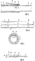
- Fig. 1 shows a partial view suction pipe 1 according to the invention for a vacuum cleaner, comprising an inner tube 2, which in an outer tube 3rd is telescopically included.
- a Handling element 4 is provided in the form of a clamp 5.
- This clamp 5 has a first section 6, which cross-section, see Fig. 3, essentially cylindrical and with its inner diameter only slightly larger than the outside diameter of the Outer tube 3 is selected.
- the clamp 5 is slotted, that is, the first section 6 forms two that Outer tube 3 encompassing more than half the circumference Side arms 31 out.
- the first section 6 is a second Section 7 assigned, which to operate the Handling element and for bringing from a rest position (Fig. 1 or Fig. 3) in a release position (Fig. 4) is pressed.
- FIG. 1 shows a longitudinal section through that in FIG. 1 Suction pipe shown 1.
- Snap-in element 9 formed in one piece, which for engagement in recesses 10 formed on the inner tube, which in shown embodiment are closed on all sides, is trained.
- This locking element 9 is actuated of the second section 7 between a rest position and one release position, since pressing the second Section 7 of the first section 6 of its quasi on the Position the outer tube in a position detached from it Position is brought, whereby the locking element 9th out of engagement with the respective recess 10 brought.
- a locking projection 11 is integrally formed, which in a engages on the outer tube 3 attached recess 12. This locking connection enables the clamp 5 on Outer tube is fixed immovably.
- Fig. 4 shows the clamp 4 in the release position, in which the lock is released and the tubes 2, 3 movable to each other.
- the clamp 4 is in this release position can be brought in that the second section in the direction Arrow A is pressed down on the outer tube 3.
- This causes the first section 6 about the pivot axis X, due to the execution of the clamp 4 in the area of the locking projection 11 lies, at least with its front, the locking element 9 carrying area pivoted upwards is in the position shown in Fig. 4.
- the Locking element 9 from its engagement with the locking recess 10 brought so that the tubes 2, 3, which by itself Known anti-rotation device 16 cannot be rotated relative to one another are held apart or in the longitudinal direction can be pushed into each other.
- FIGS. 1 to 4 Another embodiment of the handling element that essentially that with reference to FIGS. 1 to 4 corresponds to that described, Fig. 5. Also in this Handling element 18, which is also in the form of a clamp 19 is formed, that is on the inner wall 20 Locking element 21 integrally formed.
- This embodiment is dispensed with however, to that envisaged in the above and the Comprehensive projection 11 and the recess 12 Means to set, rather, is a comprehensive axial as well as torsion-proof fixing solely by means of the Latching element 21 realized.
- the outer tube 3 is provided with an opening 22, which is through the liner 13 continues. This opening 22nd is penetrated by the locking element 21, which in the Can engage recesses 10. Since the locking element 21st also in the release position not out of engagement with the Breakthrough device 22 is in this way for a sufficient fixation is ensured.
- FIGS. 6 and 7 reproduced.
- the in Fig. 4 shown anti-rotation 16 dispenses, rather the anti-rotation device is integrated in the top Locking mechanism formed.
- a Inner tube 2 provided in the longitudinal direction groove 23, which the individual recesses 10 with each other connects.
- the depth of this groove 23 is, cf. Fig. 7, deeper dimensioned as the locking recesses 10.
- this embodiment is furthermore a useful pin 25 molded on, which engages in the groove 23.
- the depth of the Groove 23 as well as the length of the useful pin 25 are included dimensioned such that the useful pin 25 is always in engagement with the groove 23 is, even if the locking element in the Was released, that is, if that Locking element 24 out of engagement with the locking recess 10 stands.
- Fig. 8 shows a further embodiment of the Handling element.
- This consists of a lever arm 26, which on a suitable bearing block 27 or the like is pivotally mounted about a pivot axis.
- the locking element 28 projecting.
- an elastic element 32 in the form arranged a coil spring, which is used to generate the Restoring force is used, the lever arm 26 always in the Rest position urges.
- the attachment to the bearing block 27 is elastic, that is, when the Attachment of the lever arm 26 already one sufficiently elastic movement to produce a Restoring force can be applied to the elastic element 32 can also be dispensed with.
- the embodiment can also be chosen such that the bearing block 27 in one piece with the lever arm 26 and on the outer tube 3 accordingly is locked, allowing one accordingly elastic pivotability.
Abstract
Description
Die Erfindung betrifft ein teleskopierbares Saugrohr für Staubsauger, bestehend aus zwei ineinander verschiebbaren Rohren, wobei das Innenrohr mehrere in Achsrichtung voneinander beabstandete Rasteintiefungen aufweist, in die zum Arretieren der Rohre zueinander unter Betätigung eines am Außenrohr angeordneten Handhabungselements ein Rastelement lösbar einrastbar ist.The invention relates to a telescopic suction pipe for Vacuum cleaner, consisting of two slidable Pipes, the inner pipe several in the axial direction has spaced-apart locking recesses into which to lock the pipes to each other by pressing one arranged on the outer tube handling element Locking element is releasably latchable.
Ein derartiges Saugrohr ist beispielsweise aus DE 195 24 290 C1 bekannt. Die Teleskopierbarkeit unter gleichzeitiger Verrastung der einzelnen Rohrstellungen zueinander wird mittels eines walzenförmigen Rastelements ermöglicht, welches in geeignete Rasteintiefungen am Innenrohr einrastbar ist. Um ein Verschieben der Rohre zueinander zu ermöglichen, ist ein Handhabungselement in Form eines am Außenrohr angebrachten Schiebers, welcher gegen die Wirkung einer Feder verspannbar ist, vorgesehen. Um das Rastelement aus seinem Rasteingriff zu bringen, muß der Schieber betätigt werden, so daß ein Freiraum oberhalb vom Rastelement geschaffen wird, in welches dieses ausrücken kann. Nachteilig bei diesem Saugrohr ist der komplette äußerst aufwendige Aufbau, da dieser einerseits eine Vielzahl von Elementen, nämlich das separate Rastelement, die Feder, und die sich ebenfalls aus mehreren Teilen zusammensetzende Schiebermimik umfaßt. Darüber hinaus ist auch die gesamte Halterung am Außenrohr äußerst kompliziert und insbesondere aus fertigungstechnischer Hinsicht unvorteilhaft. Such a suction pipe is, for example, from DE 195 24 290 C1 known. The telescopability under simultaneous Locking the individual pipe positions to each other by means of a roller-shaped locking element, which in suitable recesses on the inner tube can be snapped into place. To move the pipes towards each other enable is a handling element in the form of a Outer tube attached slider, which against the effect a spring can be tensioned. To the locking element to bring out of its locking engagement, the slide be operated so that a free space above Snap element is created, in which this disengage can. The disadvantage of this intake manifold is the complete one extremely complex structure, because this one hand Multitude of elements, namely the separate locking element, the spring, and which is also made up of several parts Composing slide facial expressions includes. Beyond that the entire bracket on the outer tube is extremely complicated and especially from a manufacturing point of view unfavorable.
Der Erfindung liegt damit das Problem zugrunde, eine teleskopierbares Saugrohr anzugeben, welches in seinem Aufbau äußerst einfach gestaltet ist bei gleichzeitiger einfacher Handhabung und Gewährleistung einer sicheren Verrastung der Einzelstellungen.The invention is therefore based on the problem of a specify telescopic suction tube, which in its Structure is extremely simple at the same time easy handling and ensuring a safe Locking the individual positions.
Zur Lösung dieses Problems ist bei einem Saugrohr der eingangs genannten Art erfindungsgemäß vorgesehen, daß das Handhabungselement am Außenrohr gegen die Wirkung einer Rückstellkraft derart hebelartig schwenkbar angeordnet ist, daß das am Handhabungselement angeordnete Rastelement bei Betätigung des Handhabungselements reversibel zwischen einer Rast- und einer Lösestellung bewegbar ist.To solve this problem is the suction pipe initially mentioned type provided according to the invention that the Handling element on the outer tube against the effect of a Restoring force is arranged so that it can be pivoted like a lever, that the locking element arranged on the handling element Operation of the handling element reversible between a locking and a release position is movable.
Die Erfindung geht also von dem im Stand der Technik bekannten Weg der Verwendung von Schiebern und separaten Rastelementen ab und macht sich die vorteilhafte Schwenklagerung des Handhabungselementes zunutze. Das Rastelement ist vorteilhaft am Handhabungselement direkt angeordnet, stellt also kein separates Teil mehr da, weshalb auch hieraus neben den sich aus der einfachen Schwenkbarkeit ergebenden Vorzügen besondere Vorteile ergeben. Denn das Handhabungselement wird einfachst vollständig unter Lösen der Arretierung verschwenkt, so daß die Einzelrohre gegeneinander verschiebbar sind, und wird durch die Wirkung der Rückstellkraft in die Raststellung bei Lösen der zum Verschwenken aufzuwendenden Kraft gebracht. Auf diese Weise ist ein äußerst einfach handzuhabendes wie herzustellendes System realisiert, das die eingangs beschriebenen Nachteile nicht mehr aufweist.The invention therefore proceeds from that in the prior art known way of using sliders and separate Locking elements and makes the advantageous Take advantage of the pivoting bearing of the handling element. The Locking element is advantageous directly on the handling element arranged, no longer represents a separate part, which is why, in addition to the simple Advantages that can be swiveled have particular advantages surrender. Because the handling element becomes the simplest pivoted completely while releasing the lock, so that the individual tubes are displaceable against each other, and will by the effect of the restoring force in the locking position when releasing the force to be pivoted brought. In this way, it is extremely simple system that can be handled and manufactured, that no longer has the disadvantages described above.
Im Rahmen einer ersten Erfindungsalternative kann vorgesehen sein, daß das Handhabungselement als das Außenrohr um mehr als den halben Umfang umgreifende, geschlitzte Schelle ausgebildet ist, die einen das Außenrohr umgreifenden, in einem mehr als den halben Umfang umgreifenden Bereich an die Außenwandung des Außenrohres anlegbaren und das Rastelement tragenden ersten Abschnitt und einen zum Schwenken zu betätigenden zweiten Abschnitt aufweist, wobei der erste Abschnitt derart elastisch ausgebildet ist, daß bei Betätigen des zweiten Abschnitts der dabei bezüglich der Außenwandung des Außenrohres bewegte erste Abschnitt unter Erzeugung einer Rückstellkraft vorspannbar ist. Diese vorteilhafte Lösung verwendet lediglich ein einziges Element, nämlich die Schelle, die das Außenrohr umgreift und durch ihre konkrete Ausbildung und Eigenelastizität unter Erzeugen einer Rückstellkraft vorspannbar ist, so daß keine weiteren Elemente mehr erforderlich sind. Dabei hat es sich als zweckmäßig erwiesen, wenn der Innendurchmesser zumindest eines Teilbereichs des ersten Abschnitts nur unwesentlich größer als der Außendurchmesser des Außenrohres gewählt ist, und wenn der zweite Abschnitt, gegebenenfalls bereits ein mit dem zweiten Abschnitt verbundener Bereich des ersten Abschnitts, bezüglich des ersten Abschnitts, gegebenenfalls dessen Teilbereichs gewinkelt angeordnet ist. Aufgrund dieser winkligen Ausbildung des Handhabungselementes ist eine einfache Verschwenkmöglichkeit mit lediglich einem einzigen am Außenrohr anzubringenden Teil, nämlich dem Handhabungselement selbst realisiert, da bedingt durch die im Durchmesser entsprechend bemessene Ausbildung des ersten Abschnitts dieser das Außenrohr umgreift, so daß der zweite Abschnitt entsprechend vom Außenrohr absteht und mühelos betätigt werden kann. As part of a first invention alternative be provided that the handling element as the Outer tube encompassing more than half the circumference, slotted clamp is formed, the one Encompassing the outer tube, to more than half the extent encompassing area on the outer wall of the outer tube can be put on and carrying the latching element first section and a second section to be operated for pivoting has, the first section being so elastic is formed that when pressing the second section which with respect to the outer wall of the outer tube moved first section generating one Restoring force can be preloaded. This advantageous solution uses only one element, namely the Clamp that encompasses the outer tube and through its concrete Training and self-elasticity while creating one Restoring force can be preloaded, so that no further Items are needed more. It turned out to be Proven useful if the inside diameter at least of a part of the first section is only insignificant selected larger than the outer diameter of the outer tube and if the second section, possibly already an area of the first section, with respect to the first section, if necessary, its partial area is arranged at an angle is. Because of this angular formation of the Handling element is a simple one Possibility of pivoting with just a single am Part to be attached to the outer tube, namely the Handling element itself realized because of the Training of the first dimensioned accordingly Section of this engages around the outer tube, so that the second Section protrudes from the outer tube accordingly and effortlessly can be operated.
In weiterer Erfindungsausgestaltung können Mittel zum axialen und/oder verdrehsicheren Festlegen der Schelle bezüglich des Außenrohres vorgesehen sein, die zum einen als Rastmittel ausgebildet sein können, umfassend einen an der Innenwandung der Schelle, insbesondere im Bereich des ersten Abschnitts ausgebildeten Rastvorsprung und eine am Außenrohr ausgebildete Rasteintiefung, welche es ermöglichen, daß die Schelle sowohl axial als auch verdrehsicher festgelegt ist, wobei zum verdrehsicheren Festlegen die Rasteintiefung letztlich allseitig geschlossen ausgebildet ist. Zusätzlich oder insbesondere für den Fall, daß die Rasteintiefung beispielsweise als am Außenrohr mantelseitig umlaufende Rastnut ausgebildet ist, können die Mittel eine am Außenrohr vorgesehene, vom Rastelement durchsetzte Ausnehmung oder Durchbrechung aufweisen, wobei insbesondere die Durchbrechungs-Lösung von Vorteil ist, als dann die vorgenannten Mittel, nämlich der an der Innenwandung der Schelle ausgebildete Rastvorsprung und die ihm zugeordnete Rasteintiefung, entfallen können, da bedingt durch die allseitig geschlossene, vom Rastelement durchsetzte Durchbrechung ein vollumfängliches Haltern gewährleistet ist. Das Rastelement selbst ist zweckmäßig an der Innenwandung der Schelle vorspringend angeordnet.In a further embodiment of the invention, means for axial and / or non-rotatable fixing of the clamp be provided with respect to the outer tube, the one can be designed as locking means, comprising one the inner wall of the clamp, especially in the area of first section trained locking projection and a Outer tube trained recess, which it allow the clamp to be both axial and is fixed against rotation, whereby for rotation-proof Ultimately define the recessed recess on all sides is closed. In addition or in particular in the event that the recessed recess, for example, as on Outer tube circumferential locking groove is formed, can the means provided on the outer tube, from Locking element penetrated recess or opening have, in particular the breakthrough solution of The advantage is that the aforementioned means, namely the locking projection formed on the inner wall of the clamp and the rest area assigned to it, can be omitted, because due to the closed on all sides, from Locking element penetrated a full extent Holders is guaranteed. The locking element itself is Expediently protruding on the inner wall of the clamp arranged.
Zur Erhöhung der Rückstellkraft kann in weiterer Erfindungsausgestaltung ein bei Betätigung des zweiten Abschnitts betätigtes elastisches Element, vorzugsweise ein Feder- oder Gummielement vorgesehen sein, welches zweckmäßig am Außenrohr im Bereich des zweiten Abschnitts oder am zweiten Abschnitt selbst, zum Außenrohr weisend, angeordnet ist, da der zweite Abschnitt vom Außenrohr ohnehin beabstandet ist. Ist die Schelle aber mit ihrem ersten Abschnitt nicht unmittelbar nicht voll aufliegend am Außenrohr angeordnet, sondern auf einem geeigneten Lagerblock oder dergleichen, kann das elastische Element natürlich auch im Bereich des ersten Abschnitts vorgesehen sein.In order to increase the restoring force Invention design one when operating the second Section actuated elastic element, preferably a Spring or rubber element may be provided, which Appropriately on the outer tube in the area of the second section or on the second section itself, facing the outer tube, is arranged because the second section of the outer tube is spaced anyway. But is the clamp with her first section not immediately lying fully on Outer tube arranged, but on a suitable Bearing block or the like, the elastic element naturally also provided in the area of the first section be.
Eine weitere Erfindungsalternative sieht vor, daß das Handhabungselement als am Außenrohr gegebenenfalls lösbar anbringbarer Hebelarm ausgebildet ist, dem zur Erzeugung einer Rückstellkraft ein bei Betätigung des Hebelarms betätigtes elastisches Element zugeordnet ist. Dieses elastische Element kann, am Außenrohr oder am Hebelarm angeordnet, sich zwischen dem Hebelarm und dem Außenrohr erstrecken. Alternativ hierzu ist auch denkbar, daß der Hebelarm mittels eines in eine am Außenrohr ausgebildete Rastausnehmung einrastbaren Rastfußes oder dergleichen am Außenrohr befestigbar ist, wobei der Rastfuß, das elastische Element bildend, derart elastisch ausgebildet ist, daß bei Verschwenken des Hebelarms die Rückstellkraft erzeugt wird. Zweckmäßigerweise kann in diesem Fall ein weiteres elastisches Element, vorzugsweise ein Feder- oder Gummielement vorgesehen sein, welches sich zwischen dem Hebelarm und dem Außenrohr erstreckt und bei Betätigung des Hebelarms betätigt wird.Another alternative to the invention provides that the Handling element as optionally detachable on the outer tube attachable lever arm is designed to generate a restoring force when the lever arm is actuated actuated elastic element is assigned. This elastic element can, on the outer tube or on the lever arm arranged between the lever arm and the outer tube extend. Alternatively, it is also conceivable that the Lever arm by means of a in a formed on the outer tube Locking recess snap-lock foot or the like on The outer tube can be fastened, the snap-in foot being the forming elastic element, formed so elastic is that when the lever arm is pivoted, the restoring force is produced. In this case, a can expediently be another elastic element, preferably a spring or Rubber element may be provided, which is between the Lever arm and the outer tube extends and when the Lever arm is actuated.
Insbesondere für den Fall, daß die Rohre aus Kunststoff sind, hat es sich als zweckmäßig erwiesen, wenn die am Innenrohr ausgebildeten Rasteintiefungen als umlaufende Rastnuten ausgebildet sind, wobei alternativ hierzu wie auch in dem Fall, daß die Rohre aus Metall sind, die am Innenrohr ausgebildeten Rasteintiefungen in ihren Abmessungen begrenzt und im wesentlichen den Abmessungen des Rastelements entsprechend ausgebildet sind, insbesondere in Form von Rastkerben. Especially in the event that the pipes are made of plastic are, it has proven to be useful if the on Inner tube trained recesses as a circumferential Locking grooves are formed, alternatively like also in the event that the pipes are made of metal, the Inner tube trained recesses in their Dimensions limited and essentially the dimensions are designed accordingly, especially in the form of notches.
Da bei der Handhabung die Saugdüse, die in der Regel beweglich am Innenrohr angeordnet ist, durch entsprechendes Verdrehen des gesamten Saugrohres in ihrer Richtung gesteuert wird, ist es zweckmäßig, wenn Mittel zum Verhindern eines Verdrehens der Rohre zueinander vorgesehen sind, welche in einer Ausführungsform in bekannter Weise als am Innenrohr ausgebildete, in Längsrichtung verlaufende Nut ausgeführt sein können, in welche eine geeignete Komplementärnase am Außenrohr oder an einer zwischen Innen- und Außenrohr angeordneten Einlage, z. B. Filz eingreift und so ein Verdrehen verhindert. Alternativ hierzu kann vorgesehen sein, daß die Mittel eine an der Außenwandung des Innenrohres in axialer Richtung verlaufende, die Rasteintiefungen miteinander verbindende Nut und eine am Rastelement ausgebildeten, in die Nut eingreifenden Nutzapfen umfassen, wobei die Tiefe der Nut größer als die Tiefe der Rastausnehmungen ist und derart bemessen ist, daß der in seiner Länge entsprechend bemessene Nutzapfen sowohl in der Rast- wie in der Lösestellung des Rastelements in die Nut eingreift.Because when handling the suction nozzle, which is usually is movably arranged on the inner tube by appropriate Turn the entire suction pipe in their direction is controlled, it is appropriate if means for Prevent twisting of the tubes to each other which, in one embodiment, are known as trained on the inner tube, extending in the longitudinal direction Can be designed in a suitable groove Complementary nose on the outer tube or on a between inner and Outer tube arranged insert, for. B. Felt engages and thus prevents twisting. Alternatively, you can be provided that the means one on the outer wall of the inner tube extending in the axial direction, the Locking recesses connecting groove and an am Locking element trained, engaging in the groove Include utility pins, the depth of the groove being greater than that Depth of the recesses is and is dimensioned such that the length of the useful pin, which is dimensioned accordingly in the locking as in the release position of the locking element in the groove engages.
Zweckmäßigerweise ist das Handhabungselement aus Kunststoff oder aus Metall gebildet.The handling element is expediently made of plastic or made of metal.
Weitere Vorteile, Merkmale und Einzelheiten der Erfindung
ergeben sich aus den im folgenden beschriebenen
Ausführungsbeispielen sowie anhand der Zeichnungen. Dabei
zeigen:
Fig. 1 zeigt in ausschnittsweiser Ansicht ein
erfindungsgemäßes Saugrohr 1 für einen Staubsauger,
umfassend ein Innenrohr 2, das in einem Außenrohr 3
teleskopierbar aufgenommen ist. Um die beiden Rohre 2, 3 in
der jeweiligen Stellung zueinander festzulegen, ist ein
Handhabungselement 4 in Form einer Schelle 5 vorgesehen.
Diese Schelle 5 weist einen ersten Abschnitt 6 auf, welcher
querschnittlich, vergleiche Fig. 3, im wesentlichen
zylinderförmig und mit seinem Innendurchmesser nur
unwesentlich größer als der Außendurchmesser des
Außenrohres 3 gewählt ist. Die Schelle 5 ist geschlitzt,
das heißt, der erste Abschnitt 6 bildet quasi zwei das
Außenrohr 3 um mehr als den halben Umfang umgreifende
Seitenarme 31 aus. Dem ersten Abschnitt 6 ist ein zweiter
Abschnitt 7 zugeordnet, welcher zur Betätigung des
Handhabungselementes und zum Bringen von einer Raststellung
(Fig. 1 bzw. Fig. 3) in eine Lösestellung (Fig. 4) zu
betätigen ist.Fig. 1 shows a partial
Fig. 1 zeigt einen Längsschnitt durch das in Fig. 1
gezeigte Saugrohr 1. An der Innenwandung 8 der Schelle 5
und im Bereich des ersten Abschnitts 6 ist zum einen ein
Rastelement 9 einstückig angeformt, welches zum Eingreifen
in am Innenrohr ausgebildete Rasteintiefungen 10, die im
gezeigten Ausführungsbeispiel allseitig geschlossen sind,
ausgebildet ist. Dieses Rastelement 9 wird durch Betätigung
des zweiten Abschnitts 7 zwischen einer Raststellung und
einer Lösestellung bewegt, da mit Betätigen des zweiten
Abschnitts 7 der erste Abschnitt 6 von seiner quasi auf dem
Außenrohr aufliegenden Stellung in eine davon gelöste
Stellung gebracht wird, wodurch auch das Rastelement 9
außer Eingriff mit der jeweiligen Rasteintiefung 10
gebracht wird. Um im gezeigten Beispiel die Schelle 5 axial
am Außenrohr 3 festzulegen, insbesondere dann, wenn sie in
die Lösestellung gebracht ist, ist an der Innenwandung 8
ein Rastvorsprung 11 einstückig angeformt, welcher in eine
am Außenrohr 3 angebrachte Rasteintiefung 12 eingreift.
Diese Rastverbindung ermöglicht es, daß die Schelle 5 am
Außenrohr unverschiebbar festgelegt ist.FIG. 1 shows a longitudinal section through that in FIG. 1
Suction pipe shown 1. On the
Die Fig. 3 und 4 zeigen nun die Wirkungsweise des
Handhabungselementes. Fig. 3 zeigt dabei eine
Schnittansicht auf die unbetätigte Schelle in Richtung der
Linie III-III aus Fig. 1. Ersichtlich liegt der erste
Abschnitt 6 mit seinen Seitenarmen 31 quasi vollflächig am
Umfang des Außenrohres 3 auf. Zwischen dem Außenrohr 3 und
dem Innenrohr 2 ist zur Führung der beiden Rohre eine
Zwischenlage 13 aus Papierfilz oder dergleichen
eingebracht. In der Aufsicht wird ferner die Ausbildung des
Rastelements 9, das hier als Vorsprung ausgebildet ist,
ersichtlich. Dieses befindet sich in der Raststellung, in
welcher es in die Rasteintiefung 10 eingreift. Damit es in
diese eingreifen kann, ist endseitig am Außenrohr 3 wie
auch an der Zwischenlage 13 eine entsprechende Ausnehmung
14, 15 ausgebildet, durch welche das Rastelement
hindurchgreifen und in die Rasteintiefung 10 gelangen kann.
Diese Ausnehmungen 14, 15, die ein Verdrehen verhindern,
können dann entfallen, wenn das Rastelement 9 in
vorgezogener Stellung angeordnet ist und sich quasi in
einem Bereich entfernt vom Außenrohr befindet.3 and 4 now show the operation of the
Handling element. 3 shows one
Sectional view of the unactuated clamp towards the
Line III-III from Fig. 1. Obviously the first is
Fig. 4 zeigt die Schelle 4 in der Lösestellung, in welcher
die Arretierung aufgehoben ist und die Rohre 2, 3 beweglich
zueinander sind. In diese Lösestellung ist die Schelle 4
dadurch bringbar, daß der zweite Abschnitt in Richtung
Pfeils A nach unten auf das Außenrohr 3 gedrückt wird. Dies
bewirkt, daß der erste Abschnitt 6 um die Schwenkachse X,
die bedingt durch die Ausführung der Schelle 4 im Bereich
des Rastvorsprungs 11 liegt, zumindest mit seinem vorderen,
das Rastelement 9 tragenden Bereich nach oben geschwenkt
wird in die in Fig. 4 gezeigte Stellung. Hierbei wird das
Rastelement 9 aus seinem Eingriff mit der Rasteintiefung 10
gebracht, so daß die Rohre 2, 3, die durch die an sich
bekannte Verdrehsicherung 16 zueinander unverdrehbar
gehaltert sind, in Längsrichtung auseinander oder
ineinander geschoben werden können. Mit dem Verschwenken
des ersten Abschnitts 6 werden gleichzeitig die beiden
Seitenarme 31, die zumindest in ihren unteren Endbereichen
17 auch während des Verschwenkens an der Außenwandung des
Außenrohres 3 anliegen, längs dieser bewegt. Infolge des in
dieser Bewegungsrichtung zunehmenden Durchmessers des
Außenrohres werden die Seitenarme 31 der Schelle 5
auseinandergedrückt, wodurch bedingt durch die elastische
Ausbildung der Schelle 5, die bevorzugt aus Kunststoff
gebildet ist, die Rückstellkraft erzeugt wird. Das heißt,
der erste Abschnitt wird vorgespannt. Diese Rückstellkraft
ermöglicht es, daß nach Lösen der auf den zweiten Abschnitt
7 wirkenden Kraft die Schelle automatisch wieder in ihre in
Fig. 3 gezeigte Raststellung gezogen wird, da die
Rückstellkraft den ersten Abschnitt in diese drängt. Durch
diese erfindungsgemäße Ausbildung der Schelle 5 wird mit
nur einem einzigen Zusatzelement zu den Rohren 2, 3 ein
vollumfänglicher und halbautomatisch wirkender Teleskopier-Rastmechanismus
geschaffen, der in seiner Einfachheit wie
auch Handhabbarkeit sich gegenüber dem Stand der Technik
auszeichnet.Fig. 4 shows the clamp 4 in the release position, in which
the lock is released and the
Eine weitere Ausführungsform des Handhabungselements, das
im wesentlichen dem bezüglich der Fig. 1 bis 4
beschriebenen entspricht, zeigt Fig. 5. Auch bei diesem
Handhabungselement 18, das ebenfalls in Form einer Schelle
19 ausgebildet ist, ist an der Innenwandung 20 das
Rastelement 21 angeformt. Diese Ausführungsform verzichtet
jedoch auf das bei der vorbeschriebenen vorgesehene und den
Rastvorsprung 11 und die Rasteintiefung 12 umfassende
Mittel zum Festlegen, vielmehr wird eine vollumfängliche
axiale wie verdrehsichere Festlegung allein mittels des
Rastelements 21 realisiert. Dies deshalb, da das Außenrohr
3 mit einer Durchbrechung 22 versehen ist, welche sich
durch die Zwischenlage 13 fortsetzt. Diese Durchbrechung 22
wird vom Rastelement 21 durchsetzt, welche in die
Rasteintiefungen 10 eingreifen kann. Da das Rastelement 21
auch in der Lösestellung nicht außer Eingriff mit der
Durchbrechung 22 gerät, wird auf diese Weise für eine
hinreichende Lagefixierung gesorgt. Another embodiment of the handling element that
essentially that with reference to FIGS. 1 to 4
corresponds to that described, Fig. 5. Also in this
Eine weitere Ausführungsform ist in den Fig. 6 und 7
wiedergegeben. Bei dieser Ausführungsform wird auf die in
Fig. 4 gezeigte Verdrehsicherung 16 verzichtet, vielmehr
ist die Verdrehsicherung integriert im oberseitigen
Rastmechanismus ausgebildet. Zu diesem Zweck ist eine am
Innenrohr 2 in Längsrichtung verlaufende Nut 23 vorgesehen,
welche die einzelnen Rasteintiefungen 10 miteinander
verbindet. Die Tiefe dieser Nut 23 ist, vgl. Fig. 7, tiefer
bemessen als die Rasteintiefungen 10. Am Rastelement 24
dieser Ausführungsform ist desweiteren ein Nutzapfen 25
angeformt, welcher in die Nut 23 eingreift. Die Tiefe der
Nut 23 wie auch die Länge des Nutzapfens 25 sind dabei
derart bemessen, daß der Nutzapfen 25 stets in Eingriff mit
der Nut 23 steht, auch wenn das Rastelement in die
Lösestellung gebracht wurde, das heißt, wenn das
Rastelement 24 außer Eingriff mit der Rasteintiefung 10
steht.Another embodiment is shown in FIGS. 6 and 7
reproduced. In this embodiment, the in
Fig. 4 shown
Schließlich zeigt Fig. 8 eine weitere Ausführungsform des
Handhabungselements. Dieses besteht aus einem Hebelarm 26,
welcher an einem geeigneten Lagerblock 27 oder dergleichen
um eine Schwenkachse verschwenkbar gelagert ist. Am
Hebelarm 26 ist das Rastelement 28 vorspringend angeordnet.
Auf der gegenüberliegenden Seite ist zwischen dem Außenrohr
3 und dem Hebelarm 26 ein elastisches Element 32 in Form
einer Schraubenfeder geordnet, welches zur Erzeugung der
Rückstellkraft dient, die den Hebelarm 26 stets in die
Raststellung drängt. Sofern die Befestigung am Lagerblock
27 elastisch ausgebildet ist, das heißt, wenn die
Befestigung des Hebelarms 26 hieran bereits eine
hinreichend elastische Bewegung unter Erzeugung einer
Rückstellkraft ermöglicht, kann auf das elastische Element
32 auch verzichtet werden. Dabei kann die Ausführungsform
auch derart gewählt sein, daß der Lagerblock 27 einstückig
mit dem Hebelarm 26 ist und an dem Außenrohr 3 entsprechend
verrastet wird, unter Ermöglichung einer entsprechend
elastischen Verschwenkbarkeit.Finally, Fig. 8 shows a further embodiment of the
Handling element. This consists of a
Claims (18)
Applications Claiming Priority (2)
| Application Number | Priority Date | Filing Date | Title |
|---|---|---|---|
| DE29619422U DE29619422U1 (en) | 1996-11-08 | 1996-11-08 | Telescopic suction pipe for vacuum cleaners |
| DE29619422U | 1996-11-08 |
Publications (2)
| Publication Number | Publication Date |
|---|---|
| EP0841033A2 true EP0841033A2 (en) | 1998-05-13 |
| EP0841033A3 EP0841033A3 (en) | 1999-04-14 |
Family
ID=8031659
Family Applications (1)
| Application Number | Title | Priority Date | Filing Date |
|---|---|---|---|
| EP97115878A Withdrawn EP0841033A3 (en) | 1996-11-08 | 1997-09-12 | Telescopic vacuum cleaner suction hose |
Country Status (4)
| Country | Link |
|---|---|
| EP (1) | EP0841033A3 (en) |
| CN (1) | CN1184622A (en) |
| DE (1) | DE29619422U1 (en) |
| PL (1) | PL323022A1 (en) |
Cited By (3)
| Publication number | Priority date | Publication date | Assignee | Title |
|---|---|---|---|---|
| WO2001045546A1 (en) * | 1999-12-21 | 2001-06-28 | Kao Corporation | Pipe connecting structure and cleaning tool |
| EP1537817A1 (en) * | 2003-12-02 | 2005-06-08 | Samsung Gwangju Electronics Co., Ltd. | Bendable extension pipe for a vacuum cleaner |
| IT202100017483A1 (en) * | 2021-07-02 | 2023-01-02 | Ams Composites S R L | SELECTIVE LOCKING DEVICE FOR TELESCOPIC ELEMENTS |
Families Citing this family (4)
| Publication number | Priority date | Publication date | Assignee | Title |
|---|---|---|---|---|
| DE10120688A1 (en) * | 2001-04-27 | 2002-11-07 | Bsh Bosch Siemens Hausgeraete | Pipe connection for a suction pipe of a vacuum cleaner |
| KR100485718B1 (en) * | 2002-12-31 | 2005-04-28 | 삼성광주전자 주식회사 | Locking device for extension pipe of vacuum cleaner |
| GB2544104B (en) * | 2015-11-06 | 2018-05-09 | Dyson Technology Ltd | Telescopic wand for a vacuum cleaner |
| CN106617829A (en) * | 2017-02-08 | 2017-05-10 | 广州视源电子科技股份有限公司 | Mobile type bracket |
Citations (10)
| Publication number | Priority date | Publication date | Assignee | Title |
|---|---|---|---|---|
| US2196459A (en) * | 1936-03-29 | 1940-04-09 | Electrolux Corp | Extensible vacuum cleaner conduit |
| NL60085C (en) * | 1943-04-09 | 1947-08-15 | ||
| US2832612A (en) * | 1953-12-04 | 1958-04-29 | Hoover Co | Suction cleaner coupling with spring biased catch |
| US3244437A (en) * | 1964-01-28 | 1966-04-05 | Electrolux Corp | Adjustable length vacuum cleaner wand |
| DE2839635A1 (en) * | 1977-10-07 | 1979-04-12 | Famulus Elektrogeraete Gmbh | Flexible locking ring for vacuum cleaner coaxial tubes - has internal radial securing plug attached to inner wall of split flexible ring |
| US4577837A (en) * | 1984-07-30 | 1986-03-25 | Marvin Berg | Locking mechanism for extendible telescoping tubular members |
| US4669755A (en) * | 1986-09-29 | 1987-06-02 | The Singer Company | Hose connection for vacuum cleaner attachments |
| DE4201855A1 (en) * | 1992-01-24 | 1993-07-29 | Licentia Gmbh | Suction hose with connector for connecting to inlet pipe in vacuum cleaner housing - makes sealed connection and in vicinity of endface section carries radially adjustable catch engaging with matching projection at vacuum cleaner housing |
| DE9213813U1 (en) * | 1992-10-13 | 1994-02-10 | Siemens Ag | Pipe connection |
| EP0616788A1 (en) * | 1993-03-24 | 1994-09-28 | AEG Hausgeräte GmbH | Vacuum cleaner hose coupling |
Family Cites Families (12)
| Publication number | Priority date | Publication date | Assignee | Title |
|---|---|---|---|---|
| US2484401A (en) * | 1946-03-05 | 1949-10-11 | William R Coie | Crutch |
| US2749153A (en) * | 1953-03-16 | 1956-06-05 | Baker Mfg Co | Spring detent coupling for telescoped parts |
| US2727762A (en) * | 1954-10-11 | 1955-12-20 | Hoover Co | Tube couplings |
| US3024031A (en) * | 1959-09-04 | 1962-03-06 | Alvin E Davidson | Tool handle adapter socket |
| DE8223754U1 (en) * | 1982-08-23 | 1982-10-07 | Marker, Hannes, 8100 Garmisch-Partenkirchen | Device for connecting telescopic step-by-step length variables |
| US4978244A (en) * | 1988-03-02 | 1990-12-18 | Interlock Structures International, Inc. | Fastener apparatus |
| DE3807028C1 (en) * | 1988-03-04 | 1989-09-07 | Heidemann-Werke Gmbh & Co Kg, 3352 Einbeck, De | Telescopic tube connection |
| DE3929399A1 (en) * | 1989-09-05 | 1991-03-21 | Heidemann Werke | Telescopic coupling for vacuum cleaner hose sections - has push-button head controlling locking device for inserted end of inner hose section |
| DE3931639C2 (en) * | 1989-09-22 | 1999-12-16 | Miele & Cie | Pipe connector between an inner tube and an outer tube with a releasable tube lock |
| SE464928B (en) * | 1989-11-01 | 1991-07-01 | Electrolux Ab | DEVICE FOR FIXING INSIDE OF EACH OTHER TELESCOPIC MOVABLE PIPES |
| DE9107725U1 (en) * | 1991-06-22 | 1991-09-12 | Marker, Hannes, 8100 Garmisch-Partenkirchen, De | |
| DE19524290C1 (en) * | 1995-07-06 | 1996-08-14 | Froh Roehren | Telescopic suction tube for vacuum cleaner with outer and inner tube |
-
1996
- 1996-11-08 DE DE29619422U patent/DE29619422U1/en not_active Expired - Lifetime
-
1997
- 1997-09-12 EP EP97115878A patent/EP0841033A3/en not_active Withdrawn
- 1997-11-06 PL PL32302297A patent/PL323022A1/en unknown
- 1997-11-06 CN CN97122425A patent/CN1184622A/en active Pending
Patent Citations (10)
| Publication number | Priority date | Publication date | Assignee | Title |
|---|---|---|---|---|
| US2196459A (en) * | 1936-03-29 | 1940-04-09 | Electrolux Corp | Extensible vacuum cleaner conduit |
| NL60085C (en) * | 1943-04-09 | 1947-08-15 | ||
| US2832612A (en) * | 1953-12-04 | 1958-04-29 | Hoover Co | Suction cleaner coupling with spring biased catch |
| US3244437A (en) * | 1964-01-28 | 1966-04-05 | Electrolux Corp | Adjustable length vacuum cleaner wand |
| DE2839635A1 (en) * | 1977-10-07 | 1979-04-12 | Famulus Elektrogeraete Gmbh | Flexible locking ring for vacuum cleaner coaxial tubes - has internal radial securing plug attached to inner wall of split flexible ring |
| US4577837A (en) * | 1984-07-30 | 1986-03-25 | Marvin Berg | Locking mechanism for extendible telescoping tubular members |
| US4669755A (en) * | 1986-09-29 | 1987-06-02 | The Singer Company | Hose connection for vacuum cleaner attachments |
| DE4201855A1 (en) * | 1992-01-24 | 1993-07-29 | Licentia Gmbh | Suction hose with connector for connecting to inlet pipe in vacuum cleaner housing - makes sealed connection and in vicinity of endface section carries radially adjustable catch engaging with matching projection at vacuum cleaner housing |
| DE9213813U1 (en) * | 1992-10-13 | 1994-02-10 | Siemens Ag | Pipe connection |
| EP0616788A1 (en) * | 1993-03-24 | 1994-09-28 | AEG Hausgeräte GmbH | Vacuum cleaner hose coupling |
Cited By (5)
| Publication number | Priority date | Publication date | Assignee | Title |
|---|---|---|---|---|
| WO2001045546A1 (en) * | 1999-12-21 | 2001-06-28 | Kao Corporation | Pipe connecting structure and cleaning tool |
| US7004671B2 (en) | 1999-12-21 | 2006-02-28 | Kao Corporation | Pipe connecting structure and cleaning tool |
| US7300077B2 (en) | 1999-12-21 | 2007-11-27 | Kao Corporation | Pipe connecting structure |
| EP1537817A1 (en) * | 2003-12-02 | 2005-06-08 | Samsung Gwangju Electronics Co., Ltd. | Bendable extension pipe for a vacuum cleaner |
| IT202100017483A1 (en) * | 2021-07-02 | 2023-01-02 | Ams Composites S R L | SELECTIVE LOCKING DEVICE FOR TELESCOPIC ELEMENTS |
Also Published As
| Publication number | Publication date |
|---|---|
| DE29619422U1 (en) | 1998-03-12 |
| CN1184622A (en) | 1998-06-17 |
| PL323022A1 (en) | 1998-05-11 |
| EP0841033A3 (en) | 1999-04-14 |
Similar Documents
| Publication | Publication Date | Title |
|---|---|---|
| DE60128015T2 (en) | Switch control device for a bicycle transmission | |
| DE102016105767B4 (en) | Endoscope control device and endoscope | |
| DE2149278B2 (en) | Device for adjusting the length of a Bowden cable cover | |
| DE202004002321U1 (en) | Positioning device for a multi-segment slide rail device for drawers | |
| EP0732893B1 (en) | Tubular-handled surgical instrument | |
| DE3046976A1 (en) | THROTTLE ADJUSTMENT | |
| DE2142887B2 (en) | Panel mountable switch | |
| EP1229258A2 (en) | Snap hook made of a body with an access aperture | |
| EP0841033A2 (en) | Telescopic vacuum cleaner suction hose | |
| DE69711405T3 (en) | CONTROL KNOB FOR HOUSEHOLD APPLIANCES | |
| DE202014100778U1 (en) | Actuation device for a parking brake | |
| WO2001029453A1 (en) | Shifting device comprising a gearshift lever for an automatic transmission of a motor vehicle | |
| EP0686552A2 (en) | A twistgrip for operating the gears of a bicycle | |
| DE102006055967A1 (en) | Seat's height adjusting unit for e.g. sports utility vehicle, has adjusting lever and transmission in effective connection over actuatable coupling unit, where movement of lever allows adjustment of seat height only in coupled condition | |
| DE8509585U1 (en) | Device for receiving or winding up a leash, in particular a dog leash (I) | |
| DE4432677B4 (en) | Endoscope tube system | |
| DE10120688A1 (en) | Pipe connection for a suction pipe of a vacuum cleaner | |
| DE102004028737A1 (en) | Actuation system for a handbrake | |
| DE102009007904A1 (en) | manual shift | |
| DE102017117655A1 (en) | two-wheel stand | |
| EP1666308A2 (en) | Universally adjustable device console. | |
| DE10051452B4 (en) | Arrangement for attaching a shower | |
| AT398701B (en) | SKI BINDING WITH ONE HEEL PART | |
| DE102006044197A1 (en) | Parking brake operating device, has tooth system with ratchet co-operating with gear segment for fixing swiveling position of handle, where ratchet has tooth that are in contact with system during fixing of handle in swiveling position | |
| DE102020104949A1 (en) | Lever for manually unlocking a seat track assembly |
Legal Events
| Date | Code | Title | Description |
|---|---|---|---|
| PUAI | Public reference made under article 153(3) epc to a published international application that has entered the european phase |
Free format text: ORIGINAL CODE: 0009012 |
|
| AK | Designated contracting states |
Kind code of ref document: A2 Designated state(s): DE ES FR GB IT |
|
| AX | Request for extension of the european patent |
Free format text: AL;LT;LV;RO;SI |
|
| PUAL | Search report despatched |
Free format text: ORIGINAL CODE: 0009013 |
|
| AK | Designated contracting states |
Kind code of ref document: A3 Designated state(s): AT BE CH DE DK ES FI FR GB GR IE IT LI LU MC NL PT SE |
|
| AX | Request for extension of the european patent |
Free format text: AL;LT;LV;RO;SI |
|
| 17P | Request for examination filed |
Effective date: 19990507 |
|
| AKX | Designation fees paid |
Free format text: DE ES FR GB IT |
|
| STAA | Information on the status of an ep patent application or granted ep patent |
Free format text: STATUS: THE APPLICATION IS DEEMED TO BE WITHDRAWN |
|
| 18D | Application deemed to be withdrawn |
Effective date: 20000401 |