EP1122880B1 - Automatische Abstimmung eines spannungsgesteuerten Oszillators - Google Patents
Automatische Abstimmung eines spannungsgesteuerten Oszillators Download PDFInfo
- Publication number
- EP1122880B1 EP1122880B1 EP01300506A EP01300506A EP1122880B1 EP 1122880 B1 EP1122880 B1 EP 1122880B1 EP 01300506 A EP01300506 A EP 01300506A EP 01300506 A EP01300506 A EP 01300506A EP 1122880 B1 EP1122880 B1 EP 1122880B1
- Authority
- EP
- European Patent Office
- Prior art keywords
- stub
- tuning
- short
- tunable device
- recited
- Prior art date
- Legal status (The legal status is an assumption and is not a legal conclusion. Google has not performed a legal analysis and makes no representation as to the accuracy of the status listed.)
- Expired - Lifetime
Links
- 238000000034 method Methods 0.000 claims description 21
- 230000001419 dependent effect Effects 0.000 claims description 20
- 238000006073 displacement reaction Methods 0.000 claims description 17
- 239000000758 substrate Substances 0.000 claims description 16
- 238000009826 distribution Methods 0.000 claims description 3
- 230000005540 biological transmission Effects 0.000 description 4
- WYTGDNHDOZPMIW-RCBQFDQVSA-N alstonine Natural products C1=CC2=C3C=CC=CC3=NC2=C2N1C[C@H]1[C@H](C)OC=C(C(=O)OC)[C@H]1C2 WYTGDNHDOZPMIW-RCBQFDQVSA-N 0.000 description 2
- 239000002184 metal Substances 0.000 description 2
- 229910052751 metal Inorganic materials 0.000 description 2
- 239000004593 Epoxy Substances 0.000 description 1
- 229910001218 Gallium arsenide Inorganic materials 0.000 description 1
- 229910000577 Silicon-germanium Inorganic materials 0.000 description 1
- 238000010420 art technique Methods 0.000 description 1
- 239000003990 capacitor Substances 0.000 description 1
- 239000000919 ceramic Substances 0.000 description 1
- 230000003247 decreasing effect Effects 0.000 description 1
- 238000010586 diagram Methods 0.000 description 1
- PCHJSUWPFVWCPO-UHFFFAOYSA-N gold Chemical compound [Au] PCHJSUWPFVWCPO-UHFFFAOYSA-N 0.000 description 1
- 239000010931 gold Substances 0.000 description 1
- 229910052737 gold Inorganic materials 0.000 description 1
- 238000004519 manufacturing process Methods 0.000 description 1
- 239000000463 material Substances 0.000 description 1
- 238000004904 shortening Methods 0.000 description 1
- 229910000679 solder Inorganic materials 0.000 description 1
- 238000005476 soldering Methods 0.000 description 1
- 239000013589 supplement Substances 0.000 description 1
- 230000007704 transition Effects 0.000 description 1
- 238000003466 welding Methods 0.000 description 1
Images


Classifications
-
- H—ELECTRICITY
- H03—ELECTRONIC CIRCUITRY
- H03B—GENERATION OF OSCILLATIONS, DIRECTLY OR BY FREQUENCY-CHANGING, BY CIRCUITS EMPLOYING ACTIVE ELEMENTS WHICH OPERATE IN A NON-SWITCHING MANNER; GENERATION OF NOISE BY SUCH CIRCUITS
- H03B5/00—Generation of oscillations using amplifier with regenerative feedback from output to input
- H03B5/18—Generation of oscillations using amplifier with regenerative feedback from output to input with frequency-determining element comprising distributed inductance and capacitance
- H03B5/1841—Generation of oscillations using amplifier with regenerative feedback from output to input with frequency-determining element comprising distributed inductance and capacitance the frequency-determining element being a strip line resonator
- H03B5/1847—Generation of oscillations using amplifier with regenerative feedback from output to input with frequency-determining element comprising distributed inductance and capacitance the frequency-determining element being a strip line resonator the active element in the amplifier being a semiconductor device
Definitions
- This invention relates to tuning voltage controlled oscillators, and in particular to automated tuning of a voltage controlled oscillator using a wire bonder to precisely establish the frequency of operation of the voltage controlled oscillator.
- Voltage controlled oscillators often have a tuning stub that is used to fine-tune the frequency of operation of the voltage controlled oscillator.
- a stub is employed to establish the frequency of operation of the voltage controlled oscillator.
- a stub short placed across conductive runners of the stub determines the frequency of operation of the voltage controlled oscillator.
- Prior techniques placed a stub short at a location along the stub that produced approximately the desired frequency of operation of the voltage controlled oscillator. The voltage controlled oscillator was powered and tested to determine the frequency of operation due to the presence of the stub short. The position of a second stub short relative to the first stub short was determined that would result in the desired frequency of operation of the voltage controlled oscillator.
- the position of the second stub short was manually measured relative to the first stub short and manually bonded along the stub to fine-tune the frequency of operation of the voltage controlled oscillator.
- the voltage controlled oscillator was again powered and the frequency of operation of the voltage controlled oscillator resulting from the presence of the second stub short was determined. If the second stub short, which was manually positioned along the stub, resulted in the desired frequency of operation of the voltage controlled oscillator, the fine-tuning was concluded.
- the second stub short was not precisely positioned along the stub, the frequency of operation of the voltage controlled oscillator was not at the desired frequency, the second stub short may have to be removed, and the process was repeated to fine-tune the frequency of operation of the voltage controlled oscillator.
- a shortcoming of the prior art technique was that the position of the second stub short was manually measured along the stub and manually secured, such as by soldering or thermosonic welding, in place.
- the stub short which is often a wire, may require being positioned with an accuracy that is less than the diameter of a cross section. Since the frequency of operation of the voltage controlled oscillator is dependent on precise positioning of the stub short along the stub, any deviation from the position that would result in the desired frequency of operation would cause the voltage controlled oscillator to operate at an undesired frequency of operation. In such cases, the stub short may have to be removed and another attempt to position and secure a short stub undertaken to establish operation of the voltage controlled oscillator at the desired frequency of operation. Such iterative steps are very costly.
- a method of tuning a tuning dependent quantity of a stub tunable device according to claim 1 According to the present invention there is also provided a method of tuning a stub tunable device according to claim 9. According to the present invention there is further provided an apparatus for tuning a stub tunable device according to claim 13.
- fine tuning the operation of a stub tunable device includes placing a first stub short across conductive runners of a tuning stub at a distance preferably greater than a distance resulting in the desired tuning dependent variable of the stub tunable device. Thereafter, the stub tunable device is powered and tested to determine an initial tuning dependent variable of operation of the stub tunable device. The position of a second stub short is determined based on the tuning dependent variable of the stub tunable device due to the presence of the first stub short, the geometry of the tuning stub and the desired of the stub tunable device.
- a second stub short is precisely positioned along the stub using automated equipment, relative to the position of the first stub short, to result in the desired tuning dependent variable of the stub tunable device.
- the first stub short may be removed. Only the stub short that results in the shortest stub length influences the tuning dependent variable. Should the second stub short require being located along the stub to result in a longer stub, then the first stub short must be modified, such as being severed or removed, so as not to influence the tuning dependent variable.
- the stub tunable device may again be powered and tested to confirm the desired tuning dependent variable of the stub tunable device.
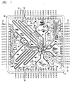
- Figure 1 is a hybrid integrated circuit 20 including a voltage controlled oscillator 60 having a tuning stub, or transmission line, tuned in accordance with an illustrative embodiment of the invention.
- a voltage controlled oscillator will be described although the invention is not limited thereto.
- Any stub tunable device including but not limited to phase shifter, delay line, timing transition detector, impedance matching, and oscillators controlled by other than voltage, may utilize the invention.
- Hybrid integrated circuit 20 includes a substrate 22 on which many components 25, including one or more integrated circuits 24 are placed.
- substrate 22 is ceramic, although the invention is not limited thereto. Any appropriate substrate material will suffice.
- Integrated circuits 24 may be manufactured by any known process including but not limited to Si, GaAs, InP, or SiGe.
- Bond pads 26 on integrated circuit 24 are connected by wire bonds 28 to other components located outside integrated circuits 24 including but are not limited to interconnects 32, conductive runners 34 of a tuning stub 36, capacitors 38 and other devices or structures adhered to substrate 22 such as by solder, bonding or epoxy.
- the invention is not limited to wire interconnects. Interconnects can be manufactured by any known process, including but not limited to flip-chip, tape-automated-bonding, or ribbon.
- Hybrid integrated circuit 20 includes bond pads 50 around the periphery which are coupled to leads 52 by wire bonds 54. Leads 52 extend through package portion 56 in which hybrid integrated circuit 20 is housed. A lid, cover or overmolding, not shown in Figure 1 , supplements package portion 56 to enclose substrate 22 in a package. There may be more than one voltage controlled oscillator having a tuning stub tuned for fine tuning the frequency of operation in accordance with the present invention.
- a tuning stub 36 having conductive runners 34 is employed to establish the frequency of operation of voltage controlled oscillator 60.
- Conductive runners 34a and 34b are shorted by a stub short 62 at some distance from ends of runners 34a and 34b coupled to bond pads 26a and 26b.
- Runners 34 form a transmission line, with ends 42 distant from bond pads 26a and 26b coupled by a via to ground. Shorting the conductive runner changes the effective length of the transmission length.
- stub short 62 may, for example, be a wire that is bonded to each runner, forming stub 36.
- the stub 36 establishes an inductance that cooperates with inherent capacitance to form a tank circuit.
- voltage controlled oscillator 60 sends a signal out on one bond pad such as bond pad 26a and receives the signal back on another bond pad, such as bond pad 26b.
- the voltage controlled oscillator signal passes from bond pad 26a through wire bond 28a thence conductive runner 34a, stub short 62, conductive runner 34b, and wire bond 28b to bond pad 26b.
- the stub length is determined by the position of stub short 62 along conductive runners 34a and 34b. Due at least in part to the stub length, a time delay is introduced into the signal that determines the frequency of operation of voltage controlled oscillator 60. The longer the stub length and hence the longer the time delay, the lower the frequency of operation of voltage controlled oscillator 60. The shorter the stub length and hence the shorter the time delay, the higher the frequency of operation of the voltage controlled oscillator 60.
- a portion of the circuitry for a voltage controlled oscillator 60 in the illustrative embodiment resides on integrated circuit 24.
- the voltage controlled oscillator 60 is coupled to conductive runners 34a and 34b of a tuning stub 36 such as through bond pads 26a and 26b and wire bonds 28a and 28b.
- Conductive runners 34a and 34b in the illustrative embodiment are two generally parallel trace structures that are laid out on a surface of substrate 24, although the invention is not limited to generally parallel trace structures as conductive runners.
- conductive runners 34a and 34b are a metal such as gold
- One skilled in the art would know how to deposit conductive runners on a substrate.
- Conductive runners 34 may be straight structures. However, since conductive runners 34 are relatively long and relatively narrow, often the layout of components on substrate 22 will not accommodate conductive runners 34 that are straight structures. Conductive runners 34 are not limited to being linear. Conductive runners 34a and 34b may serpentine back and forth to provide a longer physical length in an area of substrate 22 having a limited height and width.
- Each runner 34 forming a tuning stub need not be of the same length. When runners 34 are straight structures similar to line segments, both runners forming a tuning stub may be the same length. However, when conductive runners 34 are not straight structures similar to line segments, such as when conductive runners include a change in direction or serpentine, one conductive runner of a tuning stub may be of a different length, such as longer or shorter, than the other conductive runner of a tuning stub.
- Tuning stub 36 having conductive runners 34 that differ from those described herein are within the scope of the invention.
- the conductive runners 34 may be on opposite sides of substrate 22, may be of nonuniform cross-section, or may be structurally different from each other such as a transmission line and ground plane.
- a stub short shorting the conductive runners of a stub determines the stub length and hence frequency of operation of the voltage controlled oscillator 60.
- the operating frequency of a voltage controlled oscillator may be adjusted, or fine-tuned, knowing that only the stub short resulting in the shorter stub length determines the frequency of operation of a voltage controlled oscillator.
- a first stub short 62a (see Figures 1 and 2 ) is placed at a first location along conductive runners 34a and 34b to short the conductive runners 34a and 34b, thereby forming a first stub 36a having a first stub length.
- Stub short 62a is placed at a location based on theoretical or empirical determination of the resulting frequency of operation of voltage controlled oscillator 60.
- the location for the first stub short 62a is selected such that the resulting frequency of operation of voltage controlled oscillator 60 is preferably lower than a desired frequency of operation of voltage controlled oscillator 60.
- Stub short 62a is precisely placed along and secured, such as by bonding, to conductive runners 34a and 34b such as by an automatic wire bond machine referenced to a known reference or set of references on hybrid integrated circuit 20.
- voltage controlled oscillator 60 is powered and tested such as on a test set.
- the actual frequency of operation of voltage controlled oscillator 60 due to stub short 62a is determined. Knowing the desired frequency of operation of voltage controlled oscillator 60, the geometry of stub 36, and the actual frequency of operation of due to stub short 62a, a location along stub 36 for placement of a second stub short 62b is determined.
- the second stub short 62b position may be determined either as a displacement from the first stub short 62a, or relative to a known reference or set of references on hybrid integrated circuit 20, such as reference positions for a wire bonding machine.
- the second stub short is secured, such as by bonding, to conductive runners 34a and 34b, such as by the automatic bonding machine.
- the wire bonding machine has the capability to very precisely locate each end of a stub short 62 relative to reference positions on the hybrid integrated circuit.
- Equation (1) assumes that both ends of the second stub short 62b are displaced equal distance from corresponding ends of stub short 62a on the same conductive runner, although the invention is not limited thereto. In this manner, the physical length of the tuning stub is changed by the displacement distance as determined by Equation (1). A positive displacement means the stub length should be decreased. A negative displacement means the stub length should be increased. Equation (1) may be modified to include an offset displacement for temperature compensation.
- equation 1 One skilled in the art could modify equation 1 to accommodate geometries of other than straight conductive runners, such as a radius segment of a tuning stub, or to displace one end of a stub short 62b to be more or less distant from a corresponding end of stub short 62a on the same conductive runner.
- the first stub short 62a would be modified so as to have no influence on the frequency of operation, such as being severed or removed. There is no need to modify, sever or remove the first stub short 62a if the first stub short 62a results in a longer stub than the second stub short 62b.
- Figure 3 illustrates a system for fine tuning the frequency of operation of voltage controlled oscillator 60.
- Hybrid integrated circuit 20 is positioned on a wire bonder 70.
- wire bonder 70 When positioned on wire bonder 70, hybrid integrated circuit 20 is positioned relative to known references, including angular orientation, so that the position of each point on hybrid integrated circuit 20 is known relative to the references of the wire bonder.
- the layout of features on hybrid integrated circuit 20 are provided to wire bonder 70.
- a first stub short 62a is secured on conductive runners 34 at a location selected as described above.
- Voltage controlled oscillator 60 is powered and tested, such as on test set 72, for the frequency of operation due to the presence of first stub short 62a.
- the test set 72 employing Equation (1), calculates the displacement required to secure a second stub short to fine-tune voltage controlled oscillator 60 to operate at the desired frequency.
- the position of ends of first stub short 62a, the frequency of operation as well as the displacement calculated using Equation (1) and other parameters such as the temperature of substrate 22, along with the serial number of the hybrid integrated circuit as observed by camera 78 are collected by the test set, transferred over local area network 76 and stored in database 74.
- identifiers than the serial number, such as a bar code, may be employed.
- camera 78 may be replaced with another device, such as a bar code reader.
- the displacement calculated by Equation (1) can be generated for a range of f oper values, and the corresponding displacements stored in a look-up table. Such a technique would eliminate the on-line calculation and substitute a table look-up based on f oper to determine the displacement. Either f oper or the displacement may be stored.
- Hybrid integrated circuit 20 is again placed on wire bonder 70, typically at a later time.
- host processor 80 identifies the serial number of hybrid integrated circuit 20 and queries database 74 to obtain the displacement determined by test set 72.
- the displacement is converted by host processor 80 to represent one of a predetermined number of possible stub short positions along conductive runners 34.
- the host processor may identify 700 predetermined stub short positions, each with two known end points.
- the predetermined number of possible stub short positions are preferably at equal spaced intervals, such as 2.54 microns (0.10 mils) increments along conductive runners 34.
- the predetermined number of possible stub short positions may be symmetrical or asymmetrical about the first stub short 62.
- first stub short 62 is placed along conductive runners, as described above, to result in a stub length that is longer than the stub length to cause voltage controlled oscillator 60 to operate at the desired frequency, it is expected that most of the second stub shorts will be placed along conductive runners 34 to shorten the stub length. Thus, an asymmetric distribution of the predetermined number of possible stub short positions is preferable.
- the predetermined number of possible stub short positions may be asymmetrically distributed relative to the location of first stub short 62a.
- Figure 4 shows 12.7 x 10 -2 cm (50 mils) representing 500 stub short positions to shorten the stub length.
- the remaining 200 stub short positions represent 5.08 x 10 2 cm (20 mils) stub short positions to lengthen the stub length.
- the distance must be translated to represent one of the 700 predetermined stub short positions.
- the distance is determined to be 3.74 x 10 -2 cm (14.7 mils)
- a second stub short is secured in the predetermined stub short position determined by ten times the distance in mils, or stub short position 147.
- a positive distance indicates shortening the stub length.
- the distance determined by Equation (1) is negative, such as -1.295 x 10 -2 cm (-5.1 mils)
- the predetermined stub short position is determined by adding to 500 ten times the absolute value of the distance.
- a second stub short is positioned in predetermined stub short position 551.
- a negative distance as calculated by Equation (1) means the stub length should be increased.
Landscapes
- Inductance-Capacitance Distribution Constants And Capacitance-Resistance Oscillators (AREA)
Claims (14)
- Verfahren zum Abstimmen einer von Abstimmung abhängigen Größe einer mittels Stichleitung abstimmbaren Vorrichtung, aufweisend folgende Schritte:Auswählen einer erwünschten von Abstimmung abhängigen Größe der mittels Stichleitung abstimmbaren Vorrichtung;elektrisches Kurzschließen zweier leitfähiger Bahnen einer Abstimmstichleitung an einer ersten Position entlang der Abstimmstichleitung;Testen der mittels Stichleitung abstimmbaren Vorrichtung, um die von Abstimmung abhängige Größe zu bestimmen;Bestimmen einer zweiten Position entlang der Abstimmstichleitung, an der ein Kurzschlusselement platziert werden sollte, um die erwünschte von Abstimmung abhängige Größe der mittels Stichleitung abstimmbaren Vorrichtung zu erzeugen; undVerwenden von automatisierter Positionierungsgerätschaft zum elektrischen Kurzschließen der zwei leitfähigen Bahnen der Abstimmstichleitung an der zweiten Position entlang der Abstimmstichleitung.
- Verfahren nach Anspruch 1, wobei der Schritt des elektrischen Kurzschließens zweier leitfähiger Bahnen einer Abstimmstichleitung an einer ersten Position entlang der Abstimmstichleitung das Verwenden von automatisierter Positionierungsgerätschaft zum elektrischen Kurzschließen der zwei leitfähigen Bahnen aufweist.
- Verfahren nach Anspruch 1, wobei der Schritt des Verwendens von automatisierter Positionierungsgerätschaft das Drahtbonden eines Drahtes aufweist, um die zwei leitfähigen Bahnen elektrisch kurzzuschließen,
- Verfahren nach Anspruch 1, ferner aufweisend den Schritt des Entfernens des elektrischen Kurzschlusselements an der ersten Position entlang der Abstimmstichleitung.
- Verfahren nach Anspruch 1, wobei der Schritt des Bestimmens die zweite Position als eine Versetzung von der ersten Position aus bestimmt.
- Verfahren nach Anspruch 1, wobei der Schritt des Bestimmens die zweite Position bezüglich Referenzdaten bestimmt, die der automatisierten Positionierungsgerätschaft bekannt sind.
- Verfahren nach Anspruch 1, wobei die mittels Stichleitung abstimmbare Vorrichtung ein Oszillator ist.
- Verfahren nach Anspruch 7, wobei die von Abstimmung abhängige Größe Frequenz ist.
- Verfahren zum Abstimmen einer mittels Stichleitung abstimmbaren Vorrichtung, aufweisend folgende Schritte:Auswählen einer erwünschten von Abstimmung abhängigen Größe der mittels Stichleitung abstimmbaren Vorrichtung;elektrisches Kurzschließen zweier leitfähiger Bahnen einer Abstimmstichleitung an einer ersten Position entlang der Abstimmstichleitung;Testen der mittels Stichleitung abstimmbaren Vorrichtung, um die von Abstimmung abhängige Größe zu bestimmen;Bestimmen einer zweiten Position entlang der Abstimmstichleitung, an der ein Kurzschlusselement platziert werden sollte, um die erwünschte von Abstimmung abhängige Größe der mittels Stichleitung abstimmbaren Vorrichtung zu erzeugen;Definieren einer vorbestimmten Anzahl von möglichen zweiten Stichleitungskurzschlusspositionen entlang der leitfähigen Bahnen in der Nähe der ersten Position; Auswählen einer der vorbestimmten Anzahl von möglichen zweiten Stichleitungskurzschlusspositionen als die zweite Position; undVerwenden von automatisierter Positionierungsgerätschaft zum elektrischen Kurzschließen der zwei leitfähigen Bahnen der Abstimmstichleitung an der zweiten Position entlang der Abstimmstichleitung.
- Verfahren nach Anspruch 9, wobei das Bestimmen der vorbestimmten Anzahl von möglichen Stichleitungskurzschlusspositionen in der Nähe der ersten Position aufweist:Definieren der vorbestimmten Anzahl von möglichen Stichleitungskurzschlusspositionen in gleichen Abständen entlang der leitfähigen Bahnen.
- Verfahren nach Anspruch 9, wobei das Definieren der vorbestimmten Anzahl von möglichen zweiten Stichleitungskurzschlusspositionen in der Nähe der ersten Position aufweist:Definieren einer asymmetrischen Verteilung von möglichen zweiten Stichleitungskurzschlusspositionen um die erste Position.
- Verfahren nach Anspruch 9, wobei das Definieren der vorbestimmten Anzahl von möglichen zweiten Stichleitungskurzschlusspositionen in der Nähe der ersten Position aufweist:Definieren einer symmetrischen Verteilung von möglichen zweiten Stichleitungskurzschlusspositionen um die erste Position.
- Gerät zum Abstimmen einer mittels Stichleitung abstimmbaren Vorrichtung, aufweisend;einen Drahtbonder zum Aufnehmen eines Substrats, auf dem die mittels Stichleitung abstimmbare Vorrichtung hergestellt ist;wobei der Drahtbonder in der Lage ist, ein erstes Stichleitungskurzschlusselement an einer ersten Position entlang der Abstimmstichleitung zu platzieren:einen Detektor zum Bestimmen eines eindeutigen Substratkennzeichners;eine mit einem Wirtsrechner koppelbare Datenbank zum Speichern einer von Abstimmung abhängigen Größe einer Mehrzahl von mittels Stichleitung abstimmbaren Vorrichtungen, wobei der Wirtsrechner auf die Datenbank zugreifen kann, um die von Abstimmung abhängige Größe einer mittels Stichleitung abstimmbaren Vorrichtung auf einem Substrat, das von einem spezifischen eindeutigen Kennzeichner identifiziert wird, zu erlangen; undeinen Wirtsrechner, der mit dem Drahtbonder und dem Detektor gekoppelt ist, um mit ihnen zu kommunizieren, wobei der Wirtsrechner dazu fähig ist, zu identifizieren, an welcher einer vorbestimmten Anzahl von möglichen zweiten Stichleitungskurzschlusspositionen ein zweites Stichleitungskurzschlusselement platziert werden sollte, um die von Abstimmung abhängige Größe der mittels Stichleitung abstimmbaren Vorrichtung fein abzustimmen, wobei der Drahtbonder dafür ausgebildet ist, die identifizierte der vorbestimmten Anzahl von möglichen zweiten Stichleitungskurzschlusspositionen vom Wirtsrechner zu empfangen, wobei der Drahtbonder dazu fähig ist, dort ein zweites Stichleitungskurzschlusselement zu befestigen.
- Gerät nach Anspruch 13, wobei der Detektor eine Kamera ist.
Applications Claiming Priority (2)
| Application Number | Priority Date | Filing Date | Title |
|---|---|---|---|
| US09/495,154 US6407645B1 (en) | 2000-01-31 | 2000-01-31 | Automated voltage control oscillator tuning |
| US495154 | 2000-01-31 |
Publications (2)
| Publication Number | Publication Date |
|---|---|
| EP1122880A1 EP1122880A1 (de) | 2001-08-08 |
| EP1122880B1 true EP1122880B1 (de) | 2009-04-01 |
Family
ID=23967468
Family Applications (1)
| Application Number | Title | Priority Date | Filing Date |
|---|---|---|---|
| EP01300506A Expired - Lifetime EP1122880B1 (de) | 2000-01-31 | 2001-01-22 | Automatische Abstimmung eines spannungsgesteuerten Oszillators |
Country Status (4)
| Country | Link |
|---|---|
| US (1) | US6407645B1 (de) |
| EP (1) | EP1122880B1 (de) |
| JP (1) | JP4885367B2 (de) |
| DE (1) | DE60138149D1 (de) |
Families Citing this family (2)
| Publication number | Priority date | Publication date | Assignee | Title |
|---|---|---|---|---|
| FR2789533B1 (fr) * | 1999-02-05 | 2001-04-27 | Thomson Csf | Oscillateur a resonateur dielectrique accordable en tension |
| US20170245361A1 (en) * | 2016-01-06 | 2017-08-24 | Nokomis, Inc. | Electronic device and methods to customize electronic device electromagnetic emissions |
Family Cites Families (9)
| Publication number | Priority date | Publication date | Assignee | Title |
|---|---|---|---|---|
| US4769883A (en) | 1983-03-07 | 1988-09-13 | Westinghouse Electric Corp. | Method for tuning a microwave integrated circuit |
| JPH0323688Y2 (de) | 1984-10-04 | 1991-05-23 | ||
| JPH04117805A (ja) | 1990-09-07 | 1992-04-17 | Matsushita Electric Ind Co Ltd | 高周波電圧制御発振器 |
| US5115217A (en) | 1990-12-06 | 1992-05-19 | California Institute Of Technology | RF tuning element |
| JPH06216640A (ja) * | 1993-01-19 | 1994-08-05 | Fujitsu Ltd | 高周波回路 |
| US5537098A (en) * | 1993-04-14 | 1996-07-16 | Digital Equipment Corporation | Signaling frequency detection for a communications network |
| US5581632A (en) | 1994-05-02 | 1996-12-03 | Cognex Corporation | Method and apparatus for ball bond inspection system |
| JPH0851381A (ja) * | 1994-08-04 | 1996-02-20 | Uniden Corp | 集積化が可能な高周波用ポート選択回路 |
| US5861706A (en) * | 1997-06-10 | 1999-01-19 | Osram Sylvania Inc. | Electrodeless high intensity discharge medical lamp |
-
2000
- 2000-01-31 US US09/495,154 patent/US6407645B1/en not_active Expired - Lifetime
-
2001
- 2001-01-22 DE DE60138149T patent/DE60138149D1/de not_active Expired - Lifetime
- 2001-01-22 EP EP01300506A patent/EP1122880B1/de not_active Expired - Lifetime
- 2001-01-31 JP JP2001022575A patent/JP4885367B2/ja not_active Expired - Fee Related
Also Published As
| Publication number | Publication date |
|---|---|
| JP4885367B2 (ja) | 2012-02-29 |
| JP2001217647A (ja) | 2001-08-10 |
| DE60138149D1 (de) | 2009-05-14 |
| US6407645B1 (en) | 2002-06-18 |
| EP1122880A1 (de) | 2001-08-08 |
Similar Documents
| Publication | Publication Date | Title |
|---|---|---|
| US5594358A (en) | Radio frequency probe and probe card including a signal needle and grounding needle coupled to a microstrip transmission line | |
| FI113809B (fi) | Menetelmä älytarran valmistamiseksi sekä älytarra | |
| US7443279B2 (en) | Coil package and bias tee package | |
| DE112004002281T5 (de) | Drucksensorvorrichtung | |
| US6465896B1 (en) | Coils integrated in IC-package | |
| EP1610458B1 (de) | Oberflächenmontierter Kristaloszillator | |
| KR19990067696A (ko) | 임피던스수단 | |
| EP1122880B1 (de) | Automatische Abstimmung eines spannungsgesteuerten Oszillators | |
| JP2003115701A (ja) | 高周波フィルタ | |
| EP1851822B1 (de) | Transponder-abstimmverfahren und transponder | |
| US6661101B2 (en) | Semiconductor device | |
| KR0165135B1 (ko) | 주화검출기 | |
| EP0437976B1 (de) | Spannungskontrollierter Oszillator auf einer laminierten Leiterplatte | |
| WO2010061047A1 (en) | Tunable antenna and tuning method | |
| JP2002506303A (ja) | 金属蓋開口選択により同調する電圧制御発振器 | |
| EP0631293B1 (de) | Planar-Induktivität mit operativer Kalibrierung in einem RF-System | |
| EP0856191B1 (de) | Kondensator mit mehreren anschlüssen für einen spannungsgesteuerten oszillator | |
| JP3024900B2 (ja) | 半導体装置およびその製造方法 | |
| SE515661C2 (sv) | Trådbondningskompensering | |
| JPH0936617A (ja) | 高周波モジュール | |
| JPH0260303A (ja) | マイクロストリップ線路の共振周波調整方法 | |
| JP4749953B2 (ja) | ハイパスフィルタの製造方法 | |
| Achille et al. | Manufacturing hybrid TCXOS | |
| FI90167C (fi) | Avstaemning av en spaenningsstyrd oscillator | |
| EP1187190A1 (de) | Überwachungsmethode der Länge einer Fixlänge-Drahtverbindung und Apparat |
Legal Events
| Date | Code | Title | Description |
|---|---|---|---|
| PUAI | Public reference made under article 153(3) epc to a published international application that has entered the european phase |
Free format text: ORIGINAL CODE: 0009012 |
|
| AK | Designated contracting states |
Kind code of ref document: A1 Designated state(s): DE FR GB |
|
| AX | Request for extension of the european patent |
Free format text: AL;LT;LV;MK;RO;SI |
|
| 17P | Request for examination filed |
Effective date: 20020208 |
|
| AKX | Designation fees paid |
Free format text: DE FR GB |
|
| 17Q | First examination report despatched |
Effective date: 20080221 |
|
| GRAP | Despatch of communication of intention to grant a patent |
Free format text: ORIGINAL CODE: EPIDOSNIGR1 |
|
| GRAS | Grant fee paid |
Free format text: ORIGINAL CODE: EPIDOSNIGR3 |
|
| GRAA | (expected) grant |
Free format text: ORIGINAL CODE: 0009210 |
|
| AK | Designated contracting states |
Kind code of ref document: B1 Designated state(s): DE FR GB |
|
| REG | Reference to a national code |
Ref country code: GB Ref legal event code: FG4D |
|
| REF | Corresponds to: |
Ref document number: 60138149 Country of ref document: DE Date of ref document: 20090514 Kind code of ref document: P |
|
| RAP4 | Party data changed (patent owner data changed or rights of a patent transferred) |
Owner name: LUCENT TECHNOLOGIES INC. |
|
| PLBE | No opposition filed within time limit |
Free format text: ORIGINAL CODE: 0009261 |
|
| STAA | Information on the status of an ep patent application or granted ep patent |
Free format text: STATUS: NO OPPOSITION FILED WITHIN TIME LIMIT |
|
| 26N | No opposition filed |
Effective date: 20100105 |
|
| PGFP | Annual fee paid to national office [announced via postgrant information from national office to epo] |
Ref country code: DE Payment date: 20140115 Year of fee payment: 14 |
|
| PGFP | Annual fee paid to national office [announced via postgrant information from national office to epo] |
Ref country code: FR Payment date: 20140108 Year of fee payment: 14 |
|
| PGFP | Annual fee paid to national office [announced via postgrant information from national office to epo] |
Ref country code: GB Payment date: 20140122 Year of fee payment: 14 |
|
| REG | Reference to a national code |
Ref country code: DE Ref legal event code: R119 Ref document number: 60138149 Country of ref document: DE |
|
| GBPC | Gb: european patent ceased through non-payment of renewal fee |
Effective date: 20150122 |
|
| PG25 | Lapsed in a contracting state [announced via postgrant information from national office to epo] |
Ref country code: DE Free format text: LAPSE BECAUSE OF NON-PAYMENT OF DUE FEES Effective date: 20150801 Ref country code: GB Free format text: LAPSE BECAUSE OF NON-PAYMENT OF DUE FEES Effective date: 20150122 |
|
| REG | Reference to a national code |
Ref country code: FR Ref legal event code: ST Effective date: 20150930 |
|
| PG25 | Lapsed in a contracting state [announced via postgrant information from national office to epo] |
Ref country code: FR Free format text: LAPSE BECAUSE OF NON-PAYMENT OF DUE FEES Effective date: 20150202 |