EP1122139A1 - Vorrichtung zum Entlüften eines hydraulischen Systems und Entlüftungskit mit solcher Vorrichtung - Google Patents
Vorrichtung zum Entlüften eines hydraulischen Systems und Entlüftungskit mit solcher Vorrichtung Download PDFInfo
- Publication number
- EP1122139A1 EP1122139A1 EP00830067A EP00830067A EP1122139A1 EP 1122139 A1 EP1122139 A1 EP 1122139A1 EP 00830067 A EP00830067 A EP 00830067A EP 00830067 A EP00830067 A EP 00830067A EP 1122139 A1 EP1122139 A1 EP 1122139A1
- Authority
- EP
- European Patent Office
- Prior art keywords
- bleed
- plug
- duct
- seat
- cap
- Prior art date
- Legal status (The legal status is an assumption and is not a legal conclusion. Google has not performed a legal analysis and makes no representation as to the accuracy of the status listed.)
- Granted
Links
- 230000000740 bleeding effect Effects 0.000 claims description 6
- 230000001681 protective effect Effects 0.000 claims description 3
- 239000007788 liquid Substances 0.000 claims description 2
- 230000008878 coupling Effects 0.000 claims 1
- 238000010168 coupling process Methods 0.000 claims 1
- 238000005859 coupling reaction Methods 0.000 claims 1
- 239000012530 fluid Substances 0.000 description 3
- 230000000717 retained effect Effects 0.000 description 3
- 238000012423 maintenance Methods 0.000 description 2
- 230000036961 partial effect Effects 0.000 description 2
- 238000007789 sealing Methods 0.000 description 2
- 230000002411 adverse Effects 0.000 description 1
- 239000000428 dust Substances 0.000 description 1
- 239000007789 gas Substances 0.000 description 1
- 230000008595 infiltration Effects 0.000 description 1
- 238000001764 infiltration Methods 0.000 description 1
- 230000014759 maintenance of location Effects 0.000 description 1
- 230000000414 obstructive effect Effects 0.000 description 1
- XLYOFNOQVPJJNP-UHFFFAOYSA-N water Substances O XLYOFNOQVPJJNP-UHFFFAOYSA-N 0.000 description 1
Images


Classifications
-
- B—PERFORMING OPERATIONS; TRANSPORTING
- B60—VEHICLES IN GENERAL
- B60T—VEHICLE BRAKE CONTROL SYSTEMS OR PARTS THEREOF; BRAKE CONTROL SYSTEMS OR PARTS THEREOF, IN GENERAL; ARRANGEMENT OF BRAKING ELEMENTS ON VEHICLES IN GENERAL; PORTABLE DEVICES FOR PREVENTING UNWANTED MOVEMENT OF VEHICLES; VEHICLE MODIFICATIONS TO FACILITATE COOLING OF BRAKES
- B60T17/00—Component parts, details, or accessories of power brake systems not covered by groups B60T8/00, B60T13/00 or B60T15/00, or presenting other characteristic features
- B60T17/18—Safety devices; Monitoring
- B60T17/22—Devices for monitoring or checking brake systems; Signal devices
- B60T17/221—Procedure or apparatus for checking or keeping in a correct functioning condition of brake systems
- B60T17/222—Procedure or apparatus for checking or keeping in a correct functioning condition of brake systems by filling or bleeding of hydraulic systems
-
- B—PERFORMING OPERATIONS; TRANSPORTING
- B60—VEHICLES IN GENERAL
- B60T—VEHICLE BRAKE CONTROL SYSTEMS OR PARTS THEREOF; BRAKE CONTROL SYSTEMS OR PARTS THEREOF, IN GENERAL; ARRANGEMENT OF BRAKING ELEMENTS ON VEHICLES IN GENERAL; PORTABLE DEVICES FOR PREVENTING UNWANTED MOVEMENT OF VEHICLES; VEHICLE MODIFICATIONS TO FACILITATE COOLING OF BRAKES
- B60T11/00—Transmitting braking action from initiating means to ultimate brake actuator without power assistance or drive or where such assistance or drive is irrelevant
- B60T11/10—Transmitting braking action from initiating means to ultimate brake actuator without power assistance or drive or where such assistance or drive is irrelevant transmitting by fluid means, e.g. hydraulic
- B60T11/28—Valves specially adapted therefor
- B60T11/30—Bleed valves for hydraulic brake systems
-
- F—MECHANICAL ENGINEERING; LIGHTING; HEATING; WEAPONS; BLASTING
- F15—FLUID-PRESSURE ACTUATORS; HYDRAULICS OR PNEUMATICS IN GENERAL
- F15B—SYSTEMS ACTING BY MEANS OF FLUIDS IN GENERAL; FLUID-PRESSURE ACTUATORS, e.g. SERVOMOTORS; DETAILS OF FLUID-PRESSURE SYSTEMS, NOT OTHERWISE PROVIDED FOR
- F15B21/00—Common features of fluid actuator systems; Fluid-pressure actuator systems or details thereof, not covered by any other group of this subclass
- F15B21/04—Special measures taken in connection with the properties of the fluid
- F15B21/044—Removal or measurement of undissolved gas, e.g. de-aeration, venting or bleeding
Definitions
- the present invention relates to a bleed device for hydraulic circuits, particularly for brake circuits for vehicles, according to the precharacterizing clause of Claim 1.
- the invention also relates to a bleed kit for hydraulic circuits including the said bleed device.
- a bleed device or drain device which, in most cases, is made in the form of a threaded plug, screwed into an aperture of the hydraulic brake circuit and having a conical end which, when the plug is tightened in the aperture, bears on a seat of the aperture and acts as a valve member, or obturator, or a stopper for the aperture.
- the stopper In order for the required degree of sealing to be achieved, the stopper must be tightened against the seat with a predetermined force. This tightening, at the time of assembly of the brake, is carried out correctly by means of torque spanners.
- a drain duct or bleed duct is formed axially in the plug, and can be connected hydraulically to the circuit when the plug is slackened in the aperture.
- the first filling of the hydraulic brake circuit is normally carried out under a vacuum, and on this occasion it is not necessary to bleed the circuit by slackening the bleed plugs.
- it is possible to bleed the brake circuit by connecting the bleed duct to a small tube which drains into a bleed vessel, by pressurizing the circuit with the plug closed, slackening the plug so that air bubbles are expelled through the bleed duct, and then tightening the plug again to close the circuit.
- the operation is repeated several times for each brake, until the air or other compressible gases, which would adversely affect the operation of the brakes, are completely bled from the circuit.
- a further disadvantage to which conventional bleed devices are subject is that they permit the infiltration of any dirt and/or water which may be present, thus contaminating the brake fluid, even if the plugs are provided with protective caps.
- the problem tackled by the present invention is that of providing a bleed device for brake circuits which is structurally and functionally designed in such a way as to overcome all the disadvantages complained of with reference to the prior art mentioned above.
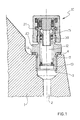
- the number 1 indicates part of a calliper for hydraulically operated disc brakes.
- the calliper 1 is connected to a hydraulic circuit for operating the brake, partly formed inside the calliper and of a conventional design, of which a short section 2, which opens into an internally threaded cylindrical aperture 3, is shown.
- a plane 4 is formed at the entry of the aperture 3.
- the circuit For bleeding the air from the circuit 2 when the circuit is being topped up or maintained, the circuit is provided with a plurality of bleed devices (at least one, as a rule, for each calliper), one of which, indicated by 10, is shown in the figure, fitted in the aperture 3 to seal it.
- the device 10 comprises a tubular body 11 in which an axial bleed duct 12 is formed and which has a flange 20 in the form of a polygonal key on its outside, in an intermediate portion.
- a first portion of the end 13 of the body 11 is externally threaded so that it can be screwed into the threaded portion of the aperture 3, the tightness of the joint being ensured by the interposition of a seal 14 between the plane 4 of the calliper 1 and a shoulder 14a of the flange 20.
- a second and opposite end portion 15 of the body 1 has on its outside a second thread 16 followed by a cylindrical portion 17 in which a groove 18 is formed.
- the portion 17 terminates in a flat annular surface 17a extending radially at the free end of the tubular body 11.
- a cap 19 is removably fitted on the second end portion 15 of the body 11 for the protection of the device 10 and for its further sealing from the exterior.
- the cap 19 is retained on the body 11 by engagement by screwing onto the second thread 16 and a further retaining means is provided by an elastic washer 21 which is simultaneously engaged in the groove 18 and in a second groove 22 of the cap.
- the hydraulic seal and protection from dust is provided by a seal 23.
- the cap 19 is also formed externally with a polygonal key 24, preferably having a different and smaller size than that of the key of the flange 20, in order to avoid the risk of accidental unscrewing of the body 11 when the cap 19 is removed.
- the cap 19 when screwed and fitted on the tubular body 11, is retained securely on it by the double engagement of two independent means of connection, on the one hand the snap-fitting of the washer 21 in the grooves 18, 22 and on the other hand the connection by screwing on to the thread 16.
- non-return check valve 26 which is normally closed with respect to the outside of the circuit 2, as explained below.
- the valve 26 comprises an obturator 27 which is normally forced to close a valve seat 28 formed in the tubular body 11.
- the valve seat 28 comprises a truncated conical annular shoulder 29 and a cylindrical linear portion 30, having a narrower cross section than the bleed duct 12.
- the linear portion 30 is provided with a seal 31 and a retaining washer 32, both housed in the same cavity 33, and terminates under the flat surface 17a.
- the obturator 27 has, in the end facing the aperture 3, an axial cavity 34 branching into ducts 35 which open on a truncated conical annular counter-shoulder 36.
- the counter-shoulder 36 normally bears on the shoulder 29; beyond this point, the obturator has a cylindrical head 37 which can engage slidably in a fluid-tight way in the linear portion 30 of the seat 28.
- the obturator 27 is normally forced to close the seat 28 by a spring 39 acting between the obturator and an elastic washer 40 retained in the bleed duct 12 near its first end.
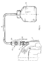
- the invention also proposes a kit specifically designed to be used with the bleed devices 10.
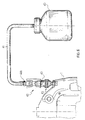
- this kit comprises a vessel 40a for collection of the bleed liquid, a tube 41 to connect the vessel 40a in a fluid-tight way to one of the devices 10 at a time, a valve 42 for shutting off the tube 41, and a quick-release connector 43 fitted to the valve 42 for the fast connection of the vessel 40a to the corresponding device 10.
- valve 42 is a conventional valve with a ball-shaped obturator 44a, while in Figure 6 it consists of a bleed plug 44b of the known type mentioned in the introductory part of the present description.
- the connector 43 comprises a main body 45 having an axial passage 46 in which a rod 46a with a truncated conical head 47 is fitted in a permanent, but non-obstructive, way.
- a tubular sleeve 48 In the passage 46 there is also fitted, slidably and in a fluid-tight way, a tubular sleeve 48, having a radial flange 49 in an intermediate position and normally forced by a spring 50 so that one of its ends bears on the shell of the head 47 to close the passage 46.
- the tightness between the sleeve 48 and the body 45 is ensured by a seal 51.
- the system comprising the vessel 40a, the tube 41 and the connector 43 is normally closed with respect to the exterior.
- the head 47 of the rod 46 acting on the obturator 27, causes it to slide in opposition to the spring 39 and consequently causes the bleed duct 12 to open.
- the tubular sleeve 48 is fitted in a fluid-tight way into the linear portion 30 of the seat 28 until its flange 49 bears on the surface 17a of the tubular body 11, resulting in the opening of the axial passage 46 by the withdrawal of the sleeve 48 from the head 47.
- the distinctive configuration of the second end of the tubular body 11, with particular reference to the configuration of the seat 28 and its linear portion 30, ensures that this acts as a quick-release connection means capable of interacting with the counter-means of quick-release connection (the tubular sleeve, rod and nut) provided by the quick-release connector 43.
Landscapes
- Engineering & Computer Science (AREA)
- Mechanical Engineering (AREA)
- Transportation (AREA)
- Chemical & Material Sciences (AREA)
- Analytical Chemistry (AREA)
- Physics & Mathematics (AREA)
- Fluid Mechanics (AREA)
- General Engineering & Computer Science (AREA)
- Valves And Accessory Devices For Braking Systems (AREA)
- Braking Arrangements (AREA)
- Fluid-Pressure Circuits (AREA)
Priority Applications (7)
| Application Number | Priority Date | Filing Date | Title |
|---|---|---|---|
| DE60037101T DE60037101T2 (de) | 2000-01-31 | 2000-01-31 | Vorrichtung zum Entlüften eines hydraulischen Systems einer Bremse und Entlüftungskit mit solcher Vorrichtung |
| AT00830067T ATE378224T1 (de) | 2000-01-31 | 2000-01-31 | Vorrichtung zum entlüften eines hydraulischen systems einer bremse und entlüftungskit mit solcher vorrichtung |
| EP00830067A EP1122139B1 (de) | 2000-01-31 | 2000-01-31 | Vorrichtung zum Entlüften eines hydraulischen Systems einer Bremse und Entlüftungskit mit solcher Vorrichtung |
| AU2001226805A AU2001226805A1 (en) | 2000-01-31 | 2001-01-23 | Bleed device and kit for hydraulic circuits |
| PCT/EP2001/000685 WO2001056853A1 (en) | 2000-01-31 | 2001-01-23 | Bleed device and kit for hydraulic circuits |
| JP2001556719A JP4938193B2 (ja) | 2000-01-31 | 2001-01-23 | 流体圧回路のための排出装置及びキット |
| US10/182,585 US6669169B2 (en) | 2000-01-31 | 2001-01-23 | Bleed device and kit for hydraulic circuits |
Applications Claiming Priority (1)
| Application Number | Priority Date | Filing Date | Title |
|---|---|---|---|
| EP00830067A EP1122139B1 (de) | 2000-01-31 | 2000-01-31 | Vorrichtung zum Entlüften eines hydraulischen Systems einer Bremse und Entlüftungskit mit solcher Vorrichtung |
Publications (2)
| Publication Number | Publication Date |
|---|---|
| EP1122139A1 true EP1122139A1 (de) | 2001-08-08 |
| EP1122139B1 EP1122139B1 (de) | 2007-11-14 |
Family
ID=8175157
Family Applications (1)
| Application Number | Title | Priority Date | Filing Date |
|---|---|---|---|
| EP00830067A Expired - Lifetime EP1122139B1 (de) | 2000-01-31 | 2000-01-31 | Vorrichtung zum Entlüften eines hydraulischen Systems einer Bremse und Entlüftungskit mit solcher Vorrichtung |
Country Status (7)
| Country | Link |
|---|---|
| US (1) | US6669169B2 (de) |
| EP (1) | EP1122139B1 (de) |
| JP (1) | JP4938193B2 (de) |
| AT (1) | ATE378224T1 (de) |
| AU (1) | AU2001226805A1 (de) |
| DE (1) | DE60037101T2 (de) |
| WO (1) | WO2001056853A1 (de) |
Cited By (6)
| Publication number | Priority date | Publication date | Assignee | Title |
|---|---|---|---|---|
| CN102252008A (zh) * | 2011-08-03 | 2011-11-23 | 浙江大学 | 用于液压系统的自动排气阀 |
| WO2012028885A1 (en) * | 2010-09-01 | 2012-03-08 | Nigel Buchanan | Brake bleeding |
| WO2012032254A1 (fr) * | 2010-09-08 | 2012-03-15 | Airbus Operations Sas | Système de purge |
| EP2853754A1 (de) * | 2013-08-21 | 2015-04-01 | Airbus Operations Limited | Hydraulische Betätigungsanordnung |
| CZ307938B6 (cs) * | 2010-12-09 | 2019-09-04 | Dako-Cz, A.S. | Zařízení pro odvzdušnění elektro-hydraulického proporcionálního ventilu, zejména pro hydraulické brzdové systémy kolejových vozidel |
| US10682997B2 (en) | 2016-01-25 | 2020-06-16 | Liberty Vehicle Technologies Limited | Bleeding device and method of bleeding a hydraulic system |
Families Citing this family (2)
| Publication number | Priority date | Publication date | Assignee | Title |
|---|---|---|---|---|
| CN100337040C (zh) * | 2005-07-15 | 2007-09-12 | 上海昂丰矿机科技有限公司 | 双液流自动控制阀块 |
| US12392365B1 (en) * | 2024-06-19 | 2025-08-19 | Richard K. Moyers | Vacuum assisted line bleeding |
Citations (3)
| Publication number | Priority date | Publication date | Assignee | Title |
|---|---|---|---|---|
| GB2086543A (en) * | 1980-11-01 | 1982-05-12 | Lucas Industries Ltd | Improvements in trap-line pressure valves |
| DE9012781U1 (de) * | 1990-09-07 | 1990-11-15 | van den Heuvel Hydraulik GmbH, 4590 Cloppenburg | Ventil zur Be- und Entlüftung eines Druckmittelkreislaufs |
| WO1998019074A1 (en) * | 1996-10-29 | 1998-05-07 | Phoenix Systems, L.L.C. | Removal of air from hydraulic system |
Family Cites Families (12)
| Publication number | Priority date | Publication date | Assignee | Title |
|---|---|---|---|---|
| CH625065A5 (de) * | 1977-11-16 | 1981-08-31 | Avl Ag | |
| JPS5482285U (de) * | 1977-11-21 | 1979-06-11 | ||
| US4936544A (en) * | 1980-10-29 | 1990-06-26 | Proprietary Technology, Inc. | Swivelable quick connector assembly |
| US4402340A (en) * | 1981-05-01 | 1983-09-06 | Lockwood Jr Hanford N | Pressure-responsive shut-off valve |
| US4541457A (en) * | 1982-03-17 | 1985-09-17 | Colder Products Company | Two-way uncoupling valve assembly |
| JPS5918069A (ja) * | 1982-07-21 | 1984-01-30 | Iseki & Co Ltd | 走行機体 |
| JPS5918069U (ja) * | 1982-07-26 | 1984-02-03 | トキコ株式会社 | 液圧ブレ−キ配管系のエヤ−抜き装置 |
| US4786029A (en) * | 1987-11-09 | 1988-11-22 | Aeroquip Corporation | Connect-against-pressure coupling |
| JPH0512890U (ja) * | 1991-07-26 | 1993-02-19 | 株式会社コスメツク | 逆止弁付き急速継手 |
| US5365972A (en) * | 1993-07-30 | 1994-11-22 | National Coupling Co., Inc. | Undersea hydraulic coupling with bleed valve |
| US5692538A (en) * | 1994-09-21 | 1997-12-02 | National Coupling Inc. | Undersea hydraulic coupling member |
| US5683148A (en) * | 1995-05-10 | 1997-11-04 | Union Switch & Signal Inc. | Brake pipe pneumatic valve |
-
2000
- 2000-01-31 EP EP00830067A patent/EP1122139B1/de not_active Expired - Lifetime
- 2000-01-31 AT AT00830067T patent/ATE378224T1/de not_active IP Right Cessation
- 2000-01-31 DE DE60037101T patent/DE60037101T2/de not_active Expired - Lifetime
-
2001
- 2001-01-23 JP JP2001556719A patent/JP4938193B2/ja not_active Expired - Fee Related
- 2001-01-23 AU AU2001226805A patent/AU2001226805A1/en not_active Abandoned
- 2001-01-23 WO PCT/EP2001/000685 patent/WO2001056853A1/en not_active Ceased
- 2001-01-23 US US10/182,585 patent/US6669169B2/en not_active Expired - Lifetime
Patent Citations (3)
| Publication number | Priority date | Publication date | Assignee | Title |
|---|---|---|---|---|
| GB2086543A (en) * | 1980-11-01 | 1982-05-12 | Lucas Industries Ltd | Improvements in trap-line pressure valves |
| DE9012781U1 (de) * | 1990-09-07 | 1990-11-15 | van den Heuvel Hydraulik GmbH, 4590 Cloppenburg | Ventil zur Be- und Entlüftung eines Druckmittelkreislaufs |
| WO1998019074A1 (en) * | 1996-10-29 | 1998-05-07 | Phoenix Systems, L.L.C. | Removal of air from hydraulic system |
Cited By (9)
| Publication number | Priority date | Publication date | Assignee | Title |
|---|---|---|---|---|
| WO2012028885A1 (en) * | 2010-09-01 | 2012-03-08 | Nigel Buchanan | Brake bleeding |
| GB2500122A (en) * | 2010-09-01 | 2013-09-11 | Nigel Buchanan | Brake bleeding |
| WO2012032254A1 (fr) * | 2010-09-08 | 2012-03-15 | Airbus Operations Sas | Système de purge |
| US9157563B2 (en) | 2010-09-08 | 2015-10-13 | Airbus Operations Sas | Bleeding system |
| CZ307938B6 (cs) * | 2010-12-09 | 2019-09-04 | Dako-Cz, A.S. | Zařízení pro odvzdušnění elektro-hydraulického proporcionálního ventilu, zejména pro hydraulické brzdové systémy kolejových vozidel |
| CN102252008A (zh) * | 2011-08-03 | 2011-11-23 | 浙江大学 | 用于液压系统的自动排气阀 |
| CN102252008B (zh) * | 2011-08-03 | 2013-06-26 | 浙江大学 | 用于液压系统的自动排气阀 |
| EP2853754A1 (de) * | 2013-08-21 | 2015-04-01 | Airbus Operations Limited | Hydraulische Betätigungsanordnung |
| US10682997B2 (en) | 2016-01-25 | 2020-06-16 | Liberty Vehicle Technologies Limited | Bleeding device and method of bleeding a hydraulic system |
Also Published As
| Publication number | Publication date |
|---|---|
| DE60037101T2 (de) | 2008-09-18 |
| US20030141478A1 (en) | 2003-07-31 |
| EP1122139B1 (de) | 2007-11-14 |
| DE60037101D1 (de) | 2007-12-27 |
| JP4938193B2 (ja) | 2012-05-23 |
| JP2003521421A (ja) | 2003-07-15 |
| ATE378224T1 (de) | 2007-11-15 |
| US6669169B2 (en) | 2003-12-30 |
| WO2001056853A1 (en) | 2001-08-09 |
| AU2001226805A1 (en) | 2001-08-14 |
Similar Documents
| Publication | Publication Date | Title |
|---|---|---|
| JP2781463B2 (ja) | 冷凍システムのサービスアダプタ | |
| US5853071A (en) | Bleed valve for bleeding fluid from a hydraulic circuit | |
| CA1308981C (en) | Oil drain valve | |
| US4307748A (en) | Sealing devices for bleed screws | |
| US4399976A (en) | Valves with lenticular or spherical closing member | |
| SK103997A3 (en) | Valve connector | |
| AU2009201004B2 (en) | A Cartridge Filter for Aircraft | |
| US7331361B2 (en) | Pressure relief valve with direct hydraulic damping | |
| EP1122139B1 (de) | Vorrichtung zum Entlüften eines hydraulischen Systems einer Bremse und Entlüftungskit mit solcher Vorrichtung | |
| EP0380196B1 (de) | Sicherheitsverbindung für Zuführungen in rohrförmigen Körpern | |
| EP1024324B1 (de) | Vorrichtung zur Kopplung eines Ventilkörpers oder Ähnlichem mit einem Verbindungsstück | |
| CA3024391A1 (en) | Spring brake actuator with diaphragm retainer | |
| US10502274B2 (en) | Bleeding valve, a hydraulic fitting and a venting assembly for a bicycle hydraulic braking system | |
| US4524800A (en) | One-way brake bleeder check valve with sealing cap | |
| US4989639A (en) | Brake bleeder check valve | |
| CN111373185B (zh) | 软管连接器组件 | |
| US7370673B2 (en) | Self-contained isolated port | |
| EP0051993A1 (de) | Kugelhahn mit verriegeltem Küken | |
| US4869292A (en) | Brake bleeder check valve | |
| JP2004522083A (ja) | プラグ・イン式安全連結装置 | |
| US20020066487A1 (en) | Charging and evacuation valve | |
| US5016668A (en) | Connection for extensions of inflating valves of motor vehicle tires | |
| CS262667B2 (en) | Hydraulic antiskid brake system vehicles | |
| US4291726A (en) | Accumulator device having safety charging port | |
| KR100443937B1 (ko) | 밸브 연결기 |
Legal Events
| Date | Code | Title | Description |
|---|---|---|---|
| PUAI | Public reference made under article 153(3) epc to a published international application that has entered the european phase |
Free format text: ORIGINAL CODE: 0009012 |
|
| AK | Designated contracting states |
Kind code of ref document: A1 Designated state(s): AT BE CH CY DE DK ES FI FR GB GR IE IT LI LU MC NL PT SE |
|
| AX | Request for extension of the european patent |
Free format text: AL;LT;LV;MK;RO;SI |
|
| 17P | Request for examination filed |
Effective date: 20011211 |
|
| AKX | Designation fees paid |
Free format text: AT BE CH CY DE DK ES FI FR GB GR IE IT LI LU MC NL PT SE |
|
| 17Q | First examination report despatched |
Effective date: 20050623 |
|
| GRAP | Despatch of communication of intention to grant a patent |
Free format text: ORIGINAL CODE: EPIDOSNIGR1 |
|
| RTI1 | Title (correction) |
Free format text: BRAKE HYDRAULIC CIRCUIT BLEED DEVICE AND BLEED KIT INCLUDING SAID DEVICE |
|
| GRAS | Grant fee paid |
Free format text: ORIGINAL CODE: EPIDOSNIGR3 |
|
| GRAA | (expected) grant |
Free format text: ORIGINAL CODE: 0009210 |
|
| AK | Designated contracting states |
Kind code of ref document: B1 Designated state(s): AT BE CH CY DE DK ES FI FR GB GR IE IT LI LU MC NL PT SE |
|
| REG | Reference to a national code |
Ref country code: GB Ref legal event code: FG4D |
|
| REG | Reference to a national code |
Ref country code: CH Ref legal event code: EP |
|
| REG | Reference to a national code |
Ref country code: IE Ref legal event code: FG4D |
|
| REF | Corresponds to: |
Ref document number: 60037101 Country of ref document: DE Date of ref document: 20071227 Kind code of ref document: P |
|
| PG25 | Lapsed in a contracting state [announced via postgrant information from national office to epo] |
Ref country code: SE Free format text: LAPSE BECAUSE OF FAILURE TO SUBMIT A TRANSLATION OF THE DESCRIPTION OR TO PAY THE FEE WITHIN THE PRESCRIBED TIME-LIMIT Effective date: 20080214 Ref country code: CH Free format text: LAPSE BECAUSE OF FAILURE TO SUBMIT A TRANSLATION OF THE DESCRIPTION OR TO PAY THE FEE WITHIN THE PRESCRIBED TIME-LIMIT Effective date: 20071114 Ref country code: LI Free format text: LAPSE BECAUSE OF FAILURE TO SUBMIT A TRANSLATION OF THE DESCRIPTION OR TO PAY THE FEE WITHIN THE PRESCRIBED TIME-LIMIT Effective date: 20071114 Ref country code: NL Free format text: LAPSE BECAUSE OF FAILURE TO SUBMIT A TRANSLATION OF THE DESCRIPTION OR TO PAY THE FEE WITHIN THE PRESCRIBED TIME-LIMIT Effective date: 20071114 Ref country code: ES Free format text: LAPSE BECAUSE OF FAILURE TO SUBMIT A TRANSLATION OF THE DESCRIPTION OR TO PAY THE FEE WITHIN THE PRESCRIBED TIME-LIMIT Effective date: 20080225 |
|
| NLV1 | Nl: lapsed or annulled due to failure to fulfill the requirements of art. 29p and 29m of the patents act | ||
| REG | Reference to a national code |
Ref country code: CH Ref legal event code: PL |
|
| PG25 | Lapsed in a contracting state [announced via postgrant information from national office to epo] |
Ref country code: AT Free format text: LAPSE BECAUSE OF FAILURE TO SUBMIT A TRANSLATION OF THE DESCRIPTION OR TO PAY THE FEE WITHIN THE PRESCRIBED TIME-LIMIT Effective date: 20071114 |
|
| PG25 | Lapsed in a contracting state [announced via postgrant information from national office to epo] |
Ref country code: DK Free format text: LAPSE BECAUSE OF FAILURE TO SUBMIT A TRANSLATION OF THE DESCRIPTION OR TO PAY THE FEE WITHIN THE PRESCRIBED TIME-LIMIT Effective date: 20071114 |
|
| EN | Fr: translation not filed | ||
| PG25 | Lapsed in a contracting state [announced via postgrant information from national office to epo] |
Ref country code: MC Free format text: LAPSE BECAUSE OF NON-PAYMENT OF DUE FEES Effective date: 20080131 Ref country code: BE Free format text: LAPSE BECAUSE OF FAILURE TO SUBMIT A TRANSLATION OF THE DESCRIPTION OR TO PAY THE FEE WITHIN THE PRESCRIBED TIME-LIMIT Effective date: 20071114 |
|
| PLBE | No opposition filed within time limit |
Free format text: ORIGINAL CODE: 0009261 |
|
| STAA | Information on the status of an ep patent application or granted ep patent |
Free format text: STATUS: NO OPPOSITION FILED WITHIN TIME LIMIT |
|
| PG25 | Lapsed in a contracting state [announced via postgrant information from national office to epo] |
Ref country code: PT Free format text: LAPSE BECAUSE OF FAILURE TO SUBMIT A TRANSLATION OF THE DESCRIPTION OR TO PAY THE FEE WITHIN THE PRESCRIBED TIME-LIMIT Effective date: 20080414 |
|
| 26N | No opposition filed |
Effective date: 20080815 |
|
| PG25 | Lapsed in a contracting state [announced via postgrant information from national office to epo] |
Ref country code: FR Free format text: LAPSE BECAUSE OF FAILURE TO SUBMIT A TRANSLATION OF THE DESCRIPTION OR TO PAY THE FEE WITHIN THE PRESCRIBED TIME-LIMIT Effective date: 20080829 |
|
| PG25 | Lapsed in a contracting state [announced via postgrant information from national office to epo] |
Ref country code: IE Free format text: LAPSE BECAUSE OF NON-PAYMENT OF DUE FEES Effective date: 20080131 Ref country code: GR Free format text: LAPSE BECAUSE OF FAILURE TO SUBMIT A TRANSLATION OF THE DESCRIPTION OR TO PAY THE FEE WITHIN THE PRESCRIBED TIME-LIMIT Effective date: 20080215 |
|
| PG25 | Lapsed in a contracting state [announced via postgrant information from national office to epo] |
Ref country code: CY Free format text: LAPSE BECAUSE OF FAILURE TO SUBMIT A TRANSLATION OF THE DESCRIPTION OR TO PAY THE FEE WITHIN THE PRESCRIBED TIME-LIMIT Effective date: 20071114 |
|
| PG25 | Lapsed in a contracting state [announced via postgrant information from national office to epo] |
Ref country code: FI Free format text: LAPSE BECAUSE OF FAILURE TO SUBMIT A TRANSLATION OF THE DESCRIPTION OR TO PAY THE FEE WITHIN THE PRESCRIBED TIME-LIMIT Effective date: 20071114 |
|
| PG25 | Lapsed in a contracting state [announced via postgrant information from national office to epo] |
Ref country code: LU Free format text: LAPSE BECAUSE OF NON-PAYMENT OF DUE FEES Effective date: 20080131 |
|
| PGFP | Annual fee paid to national office [announced via postgrant information from national office to epo] |
Ref country code: GB Payment date: 20180119 Year of fee payment: 19 |
|
| PGFP | Annual fee paid to national office [announced via postgrant information from national office to epo] |
Ref country code: IT Payment date: 20190109 Year of fee payment: 20 |
|
| PGFP | Annual fee paid to national office [announced via postgrant information from national office to epo] |
Ref country code: DE Payment date: 20190401 Year of fee payment: 20 |
|
| GBPC | Gb: european patent ceased through non-payment of renewal fee |
Effective date: 20190131 |
|
| PG25 | Lapsed in a contracting state [announced via postgrant information from national office to epo] |
Ref country code: GB Free format text: LAPSE BECAUSE OF NON-PAYMENT OF DUE FEES Effective date: 20190131 |
|
| REG | Reference to a national code |
Ref country code: DE Ref legal event code: R071 Ref document number: 60037101 Country of ref document: DE |