EP1121919A2 - Brancard automoteur avec unité de soins intensifs portable - Google Patents
Brancard automoteur avec unité de soins intensifs portable Download PDFInfo
- Publication number
- EP1121919A2 EP1121919A2 EP00500194A EP00500194A EP1121919A2 EP 1121919 A2 EP1121919 A2 EP 1121919A2 EP 00500194 A EP00500194 A EP 00500194A EP 00500194 A EP00500194 A EP 00500194A EP 1121919 A2 EP1121919 A2 EP 1121919A2
- Authority
- EP
- European Patent Office
- Prior art keywords
- stretcher
- frame
- fact
- motors
- self
- Prior art date
- Legal status (The legal status is an assumption and is not a legal conclusion. Google has not performed a legal analysis and makes no representation as to the accuracy of the status listed.)
- Granted
Links
- 230000015572 biosynthetic process Effects 0.000 claims description 11
- 238000005755 formation reaction Methods 0.000 claims description 11
- 238000000465 moulding Methods 0.000 claims description 2
- 230000001174 ascending effect Effects 0.000 claims 1
- 239000003638 chemical reducing agent Substances 0.000 claims 1
- 230000000295 complement effect Effects 0.000 claims 1
- 238000006073 displacement reaction Methods 0.000 description 3
- 230000004308 accommodation Effects 0.000 description 2
- 238000011161 development Methods 0.000 description 2
- 238000010586 diagram Methods 0.000 description 2
- 238000010348 incorporation Methods 0.000 description 2
- 238000004519 manufacturing process Methods 0.000 description 2
- 230000006978 adaptation Effects 0.000 description 1
- 230000004075 alteration Effects 0.000 description 1
- 230000036772 blood pressure Effects 0.000 description 1
- 238000010276 construction Methods 0.000 description 1
- 230000000694 effects Effects 0.000 description 1
- 238000005516 engineering process Methods 0.000 description 1
- 238000009434 installation Methods 0.000 description 1
- 239000000463 material Substances 0.000 description 1
- 238000005259 measurement Methods 0.000 description 1
- 238000012986 modification Methods 0.000 description 1
- 230000004048 modification Effects 0.000 description 1
- 230000029058 respiratory gaseous exchange Effects 0.000 description 1
- 238000007493 shaping process Methods 0.000 description 1
- 238000012549 training Methods 0.000 description 1
Images

Classifications
-
- A—HUMAN NECESSITIES
- A61—MEDICAL OR VETERINARY SCIENCE; HYGIENE
- A61G—TRANSPORT, PERSONAL CONVEYANCES, OR ACCOMMODATION SPECIALLY ADAPTED FOR PATIENTS OR DISABLED PERSONS; OPERATING TABLES OR CHAIRS; CHAIRS FOR DENTISTRY; FUNERAL DEVICES
- A61G1/00—Stretchers
- A61G1/02—Stretchers with wheels
- A61G1/0237—Stretchers with wheels having at least one swivelling wheel, e.g. castors
-
- A—HUMAN NECESSITIES
- A61—MEDICAL OR VETERINARY SCIENCE; HYGIENE
- A61G—TRANSPORT, PERSONAL CONVEYANCES, OR ACCOMMODATION SPECIALLY ADAPTED FOR PATIENTS OR DISABLED PERSONS; OPERATING TABLES OR CHAIRS; CHAIRS FOR DENTISTRY; FUNERAL DEVICES
- A61G1/00—Stretchers
- A61G1/02—Stretchers with wheels
- A61G1/0206—Stretchers with wheels characterised by the number of supporting wheels if stretcher is extended
- A61G1/0212—2 pairs having wheels within a pair on the same position in longitudinal direction, e.g. on the same axis
-
- A—HUMAN NECESSITIES
- A61—MEDICAL OR VETERINARY SCIENCE; HYGIENE
- A61G—TRANSPORT, PERSONAL CONVEYANCES, OR ACCOMMODATION SPECIALLY ADAPTED FOR PATIENTS OR DISABLED PERSONS; OPERATING TABLES OR CHAIRS; CHAIRS FOR DENTISTRY; FUNERAL DEVICES
- A61G1/00—Stretchers
- A61G1/02—Stretchers with wheels
- A61G1/0275—Stretchers with wheels having driven wheels, e.g. motorised
-
- A—HUMAN NECESSITIES
- A61—MEDICAL OR VETERINARY SCIENCE; HYGIENE
- A61G—TRANSPORT, PERSONAL CONVEYANCES, OR ACCOMMODATION SPECIALLY ADAPTED FOR PATIENTS OR DISABLED PERSONS; OPERATING TABLES OR CHAIRS; CHAIRS FOR DENTISTRY; FUNERAL DEVICES
- A61G1/00—Stretchers
- A61G1/02—Stretchers with wheels
- A61G1/0293—Stretchers with wheels stretcher supports with wheels, e.g. used for stretchers without wheels
-
- A—HUMAN NECESSITIES
- A61—MEDICAL OR VETERINARY SCIENCE; HYGIENE
- A61G—TRANSPORT, PERSONAL CONVEYANCES, OR ACCOMMODATION SPECIALLY ADAPTED FOR PATIENTS OR DISABLED PERSONS; OPERATING TABLES OR CHAIRS; CHAIRS FOR DENTISTRY; FUNERAL DEVICES
- A61G7/00—Beds specially adapted for nursing; Devices for lifting patients or disabled persons
- A61G7/05—Parts, details or accessories of beds
- A61G7/0528—Steering or braking devices for castor wheels
-
- A—HUMAN NECESSITIES
- A61—MEDICAL OR VETERINARY SCIENCE; HYGIENE
- A61G—TRANSPORT, PERSONAL CONVEYANCES, OR ACCOMMODATION SPECIALLY ADAPTED FOR PATIENTS OR DISABLED PERSONS; OPERATING TABLES OR CHAIRS; CHAIRS FOR DENTISTRY; FUNERAL DEVICES
- A61G2210/00—Devices for specific treatment or diagnosis
- A61G2210/30—Devices for specific treatment or diagnosis for intensive care
-
- A—HUMAN NECESSITIES
- A61—MEDICAL OR VETERINARY SCIENCE; HYGIENE
- A61G—TRANSPORT, PERSONAL CONVEYANCES, OR ACCOMMODATION SPECIALLY ADAPTED FOR PATIENTS OR DISABLED PERSONS; OPERATING TABLES OR CHAIRS; CHAIRS FOR DENTISTRY; FUNERAL DEVICES
- A61G7/00—Beds specially adapted for nursing; Devices for lifting patients or disabled persons
- A61G7/08—Apparatus for transporting beds
Definitions
- the present invention relates to a device for self-propelled stretcher designed as a mobile micro-ICU, which brings essential novelty features and remarkable advantages compared to the means knows and uses for similar purposes in the state current technology.
- this invention provides the development of a set consisting of a stretcher intended transporting a patient, associated with a support frame which, in turn, is supported by a frame of a mobile unit capable of being moved across the intervention of electric motors powered from electric batteries incorporated in the set even, can be operated at will by an operator external to using conventional switching means electric, and the assembly being further designed to incorporate, preferably in the support structure of the stretcher, complete equipment necessary for attention to the patient during transport to hospital center in question.
- the object of this invention was to essential developing a stretcher set associated with a mobile unit, set in which it was planned to incorporate all means and equipment necessary to offer the patient intense attention, in a fast and followed manner, so that he enjoys the best possible vital support during transport to the destination center, and so that this unit is capable of self-displacement thanks to the incorporation of one or more electric motors, preferably powered by electric batteries, and can be operated at will using conventional means electrical switching which will consist of preferably by a "joystick" device or any other proving adequate for the intended purpose.
- this invention provides the use of a stretcher with characteristics conventional, capable of being fixed to a structure support with possibility of rotation in one of its lower points, preferably at its central point, in a rotation angle of amplitude predetermined by relative to the horizontal, for example between 0 and 30 °, and, even better, between 0 and 15 °, to provide the stretcher a corresponding inclination allowing it to adapt to the needs of each particular case.
- This support structure, or upper frame consists of several tubular elements joined together to form a rigid and empty frame inside.
- This support frame stretcher is divided into several compartments, with variable dimensions and shapes for housing several devices which constitute the equipment of the stretcher and micro-ICU assembly, and for this purpose we have provided for the formation of a body which is, by way of side frame, coupled to this frame from one on his side.
- a mobile unit frame, or bottom frame made up also from several tubular elements which provide it with the necessary rigidity, and which also empty interior for battery storage of electric motors, as well as for the adaptation of several drawers, extractable from on one side, preferably the same access side to the upper part, and by being able further access this internal space using a door on the same side.
- the mobile unit has four wheels for that it can move around comfortably, and one or several, preferably two, receive the movement at from one or more corresponding motors. These wheels are mounted on rotating supports, which allows ease and speed of direction of all depending on what is suitable. Furthermore, in the upper position and in connection with this frame lower or mobile unit, training is planned a handle, preferably consisting of a bar transverse positioning, to which we fixed, the electrical switching means which will consist, as this has been said, preferably as a "joystick" due to its easy handling and intuitive.
- the motors provided for actuating the mobile unit are DC motors so that they can be powered by batteries incorporated in the assembly, which are provided with reduction groups in order to allow the mobile unit to have a low speed of displacement, preferably a speed of the order of 3 to 8 km / h, this speed also depending on the fact that the displacement is carried out on flat paths, horizontal or inclined.
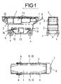
- FIG. 1 shows views in the form of diagrams in side top view, rear top view and in plan, of a mobile micro-ICU self-propelled stretcher assembly, constructed according to the present invention
- Figure 2 shows a perspective view of a dismemberment carried out across the stretcher and the mobile unit in Figure 1.
- the realization preferred object of the invention is shown under form of diagrams in the two Figures of the drawings, and according to several views.
- the element of stretcher 1 occupies the upper position and he has access from any of his four sides, in order to facilitate both the installation and transport / descent of a patient, at the same time as any attention and care operation that must be carried out during transport or while the patient is on this stretcher 1.
- the stretcher is supported by a upper support structure 2, the latter being supported in turn by a lower structure 3 belonging to the mobile unit.
- This mobile unit is provided with four wheels 4, of which at least two, by example the front wheels are mounted on supports 5 swiveling to allow convenient steering and easy of the whole while moving, while the other two, for example the rear wheels, are associated with motor elements 6, which consist of preferably geared motors driven by a direct current, and from which they receive the movement necessary to carry out the movement alleged.
- motor elements 6, consist of preferably geared motors driven by a direct current, and from which they receive the movement necessary to carry out the movement alleged.
- a tubular element 7 is raised at the rear part which folds to the top position to present part horizontal development, which can be used as handle by the user, and in which are mounted means 8 which deal with the connection / disconnection of the power supply to the motors 6, and which preferably consist of an element of the type "joystick".
- this switching device food was chosen because it has handling characteristics which may have access to any user, but this fact should not be understood as limiting or excluding, since it would be possible to pair any other device conventional allowing these operations to be carried out power connection / disconnection quickly and reliably.
- the whole was designed to allow the incorporation of any the equipment that we need to offer, in a way autonomous, complete and perfect attention to the patient.
- closing the sides of these upper and lower structures is made in using carcasses which consist, on the one hand, of generally planar elements (9, 10), the only one of which mission is to close in a way adequate space and that do not, in general, provide no other additional utility, while, on the side opposite, the respective upper carcasses (11, 12) and lower, have been shaped so that a molding or similar operation, they have been formed not only as closure panels, but also for the presentation of compartments 13, in the upper casing 11, for reception and accommodation equipment at a convenient height and easy access for the user, the formation of drawers 14 in the lower carcass 12 to be able to collect and keep, in a safe and well protected way, another set of instruments, and even the formation of a gate 15, also in the lower casing 12, to facilitate access to the interior space of structure 3 lower, where they will be housed, for example, the power supply batteries of the assembly and others devices that would be useful for operation correct of the whole.
- the 2 upper structure incorporates, on each side and near of their corners, elements 16 consisting of sleeves to perfectly grasp and manually transport the upper structure, including stretcher 1 properly said, these sleeves 16 being capable of being hidden, through an inward introduction, as long as they should not be used.
- the support structure upper to which the stretcher 1 is associated proper, consists of a tubular frame 2, which provides a completely horizontal top plane for a base 17 on the rest element, and in which is fixed stretcher 1 for the safety of its transport.
- the side carcasses 9, 11 also appear shown for illustrative purposes, and we can appreciate the formation of compartments 13 in the carcass 11, forming an integral part thereof, obtained from preferably during the shaping operation itself, likely to be accommodated in the interior space of the frame 2, as well as the relative position of the sleeves 16 on both sides.
- This interior space in frame 2 seems closed at the bottom with an element 18, designed so that it follows the very shapes of the frame, partially enveloping it, and further presenting lower formations 19 extended transversely, by means of which the structure is carried out lower.
- bar 7 which constitutes the handle element, it also appears represented separately from the other elements, so that we can assess the mode chosen for said bar, as well as its possibility of fixing using end caps lower or similar.
- supports 5 in the wheels front the position of each motor 6 with its group associated gearbox for actuating a wheel 4 respective, and also the use of an element 24 suitably shaped to close the frame 3 to its lower part, by partially enveloping it all as in the case of the upper structure.
Landscapes
- Health & Medical Sciences (AREA)
- Life Sciences & Earth Sciences (AREA)
- Animal Behavior & Ethology (AREA)
- General Health & Medical Sciences (AREA)
- Public Health (AREA)
- Veterinary Medicine (AREA)
- Nursing (AREA)
- Invalid Beds And Related Equipment (AREA)
- Handcart (AREA)
- Devices For Medical Bathing And Washing (AREA)
- Percussion Or Vibration Massage (AREA)
Abstract
Description
La Figure 1 montre des vues sous forme de schémas en vue de dessus de côté, vue de dessus arrière et en plan, d'un ensemble de brancard automoteur de micro-USI mobile, construit selon la présente invention, et
Claims (4)
- Brancard automoteur micro-USI mobile, destiné aux soins et à l'attention permanente d'un patient au cours de son transport en ambulance, brancard qui se caractérise par le fait qu'il ait été constitué à partir d'une structure supérieure associée au brancard (1) proprement dit, et une structure inférieure constituée en tant qu'unité mobile, dont ladite structure supérieure a été constituée à partir d'un cadre (2), conformé à partir d'éléments tubulaires capables de lui fournir la rigidité structurelle requise, dont la partie supérieure fournit un plan préparé pour recevoir un élément (17) de base sur lequel repose et auquel est fixé ledit élément (1) de brancard, cette structure étant fermée latéralement moyennant des carcasses (9, 11) dont une carcasse (9) est utilisée seulement comme moyen de fermeture, tandis que la carcasse (11) du côté opposé a été constituée à partir d'une pièce obtenue de préférence par moulage, configurée de sorte qu'elle ait plusieurs logements (13) avec différentes formes et dimensions, qui se projettent vers l'espace intérieur du cadre (2) même), et qui destinent à la réception, au logement et à la retenue de l'équipement nécessaire pour les soins permanents du patient, et la structure supérieure étant en outre fermée à sa partie inférieure à l'aide d'un élément (18), conformé avec une configuration complémentaire avec celle du cadre (2) afin de lui servir d'enveloppe partielle, et en ayant doté, en outre, ledit élément (18) de projections (19) transversales de fixation et de retenue, tandis que la structure inférieure ou l'unité mobile a été constituée également par des éléments tubulaires conformés d'une manière adéquate, dont le cadre (3) est préparé pour recevoir, à sa partie supérieure, un cadre (21), avec possibilité de rotation par rapport à sa partie centrale de préférence, sur lequel repose une base (22) pourvue de formations (23) transversales disposées dans des positions complémentaires avec les formations (23) de la structure supérieure, qu'elle reçoit et retient, de sorte que la rotation de ce cadre, entre des limites établies au préalable, permet le positionnement du brancard (1) avec la même inclinaison relative, et en ayant prévu aussi les carcasses latérales correspondantes (10, 12) qui sont utilisées, en correspondance avec celles (9, 10) de la structure supérieure, l'une d'elles (10) est utilisée seulement comme moyen de fermeture du côté correspondant, tandis que l'autre (12) du côté opposé à la formation de logements en guise de tiroirs, projetés vers l'espace intérieur de ce cadre (3) inférieur, ainsi que la disposition d'une porte (15) d'accès à cet espace intérieur, et en ayant fermé en outre cette structure inférieure, à sa partie inférieure, avec la collaboration d'un élément (24), également partiellement enveloppant, en disposant en outre cette structure inférieure mobile de quatre roues (4) dont deux d'entre elles sont montées sur des supports (5) rotatifs, et les deux autres sont associées à des moyens moteurs, qui consistent de préférence en des moteurs (6), avec des groupes réducteurs respectifs qui communiquent un mouvement aux roues associées pour le déplacement de l'ensemble à une vitesse comprise entre des limites prédéterminées.
- Brancard automoteur selon la lère revendication, qui se caractérise par le fait que ces moyens moteurs consistent en des moteurs (6) de courant continu, alimentés à partir de batteries comprises dans l'espace intérieur fourni par le cadre (3) inférieur.
- Brancard automoteur selon la lère ou la 2ème revendication, qui se caractérise par le fait que la structure inférieure dispose d'un élément tubulaire (7) associé qui a, en évoluant d'une manière ascendante, un tronçon supérieur horizontal susceptible d'être utilisé comme manche pour la manipulation correcte et le directionnement de l'ensemble, et le fait que soient montés des moyens (8) pour la connexion/déconnexion de l'alimentation aux moteurs (6) configurés de préférence en guise de dispositif de "joystick".
- Brancard automoteur selon l'une quelconque des revendications 1 à 3, qui se caractérise par le fait que l'on a prévu, en outre, des moyens (16) de manche de chaque côté, qui permettent de manipuler aisément et commodément et de transporter manuellement la structure inférieure, et qui sont en position de repos susceptibles de se cacher vers l'espace intérieur de cette structure.
Applications Claiming Priority (2)
| Application Number | Priority Date | Filing Date | Title |
|---|---|---|---|
| ES200000260A ES2164006B1 (es) | 2000-02-07 | 2000-02-07 | Camilla automotriz micro-uvi movil. |
| ES200000260 | 2000-02-07 |
Publications (3)
| Publication Number | Publication Date |
|---|---|
| EP1121919A2 true EP1121919A2 (fr) | 2001-08-08 |
| EP1121919A3 EP1121919A3 (fr) | 2003-03-12 |
| EP1121919B1 EP1121919B1 (fr) | 2005-06-01 |
Family
ID=8492190
Family Applications (1)
| Application Number | Title | Priority Date | Filing Date |
|---|---|---|---|
| EP00500194A Expired - Lifetime EP1121919B1 (fr) | 2000-02-07 | 2000-09-01 | Brancard automoteur avec unité de soins intensifs portable |
Country Status (4)
| Country | Link |
|---|---|
| EP (1) | EP1121919B1 (fr) |
| AT (1) | ATE296601T1 (fr) |
| DE (1) | DE60020513D1 (fr) |
| ES (2) | ES2164006B1 (fr) |
Cited By (2)
| Publication number | Priority date | Publication date | Assignee | Title |
|---|---|---|---|---|
| EP1693035A1 (fr) * | 2003-11-25 | 2006-08-23 | Medlog S.A. | Brancard automoteur utilise dans le domaine medical |
| CN101947165A (zh) * | 2010-10-13 | 2011-01-19 | 重庆理工大学 | 一种自平衡担架 |
Families Citing this family (1)
| Publication number | Priority date | Publication date | Assignee | Title |
|---|---|---|---|---|
| US12564527B2 (en) | 2022-03-07 | 2026-03-03 | Hill-Rom Services, Inc. | Patient support apparatus having motorized wheels |
Family Cites Families (9)
| Publication number | Priority date | Publication date | Assignee | Title |
|---|---|---|---|---|
| US3606302A (en) * | 1969-06-02 | 1971-09-20 | Charles D Allard | Life support cart |
| BE791665A (fr) * | 1971-12-01 | 1973-03-16 | Baxter Laboratories Inc | Brancard de secours |
| US3858570A (en) * | 1972-06-12 | 1975-01-07 | Puritan Bennett Corp | Comprehensive infant care system |
| US3838687A (en) * | 1973-06-08 | 1974-10-01 | W Mosher | Portable medical table including slidably mounted anesthesia apparatus |
| FR2285113A1 (fr) * | 1974-09-17 | 1976-04-16 | Assistance Tech Med | Chariot de reanimation |
| US4584989A (en) * | 1984-12-20 | 1986-04-29 | Rosemarie Stith | Life support stretcher bed |
| EP0630637B1 (fr) * | 1993-06-14 | 1998-12-09 | Helmut Schuster | Dispositif de transport pour patients ou personnes alitées |
| AUPM731694A0 (en) * | 1994-08-05 | 1994-09-01 | Buchanan Aircraft Corporation Limited | A stretcher style mobile intensive care unit |
| DE29806422U1 (de) * | 1998-04-08 | 1998-06-25 | Eppler, Susanne, 72770 Reutlingen | Krankentransportvorrichtung |
-
2000
- 2000-02-07 ES ES200000260A patent/ES2164006B1/es not_active Expired - Fee Related
- 2000-09-01 ES ES00500194T patent/ES2243224T3/es not_active Expired - Lifetime
- 2000-09-01 DE DE60020513T patent/DE60020513D1/de not_active Expired - Lifetime
- 2000-09-01 EP EP00500194A patent/EP1121919B1/fr not_active Expired - Lifetime
- 2000-09-01 AT AT00500194T patent/ATE296601T1/de not_active IP Right Cessation
Non-Patent Citations (1)
| Title |
|---|
| None |
Cited By (2)
| Publication number | Priority date | Publication date | Assignee | Title |
|---|---|---|---|---|
| EP1693035A1 (fr) * | 2003-11-25 | 2006-08-23 | Medlog S.A. | Brancard automoteur utilise dans le domaine medical |
| CN101947165A (zh) * | 2010-10-13 | 2011-01-19 | 重庆理工大学 | 一种自平衡担架 |
Also Published As
| Publication number | Publication date |
|---|---|
| ATE296601T1 (de) | 2005-06-15 |
| ES2164006A1 (es) | 2002-02-01 |
| DE60020513D1 (de) | 2005-07-07 |
| EP1121919A3 (fr) | 2003-03-12 |
| ES2164006B1 (es) | 2003-03-16 |
| EP1121919B1 (fr) | 2005-06-01 |
| ES2243224T3 (es) | 2005-12-01 |
Similar Documents
| Publication | Publication Date | Title |
|---|---|---|
| EP2004124B1 (fr) | Fauteuil multipositions pour handicape | |
| CA2788925C (fr) | Dispositif de franchissement d'obstacle pour fauteuil roulant electrique | |
| CA2936499A1 (fr) | Station de travail medicale extra-hospitaliere | |
| CA1250542A (fr) | Dispositif pour deplacer un malade a partir de son lit | |
| CA2821484A1 (fr) | Dispositif destine a rompre au moins un element de fermeture dispose a l'interieur d'un tube souple | |
| EP3429502A1 (fr) | Robot d'insertion d'instrument médical souple allonge et accessoires associes | |
| EP0007262A1 (fr) | Dispositif pour transborder un handicapé physique de son fauteuil roulant à un véhicule automobile et réciproquement | |
| FR2561099A1 (fr) | Lit d'hopitaux perfectionne | |
| EP2029081B1 (fr) | Dispositif de guidage pour table d'opération comprenant des bras de guidage aptes à être fixés de manière amovible sur ladite table, et table d'opération comportant de tels bras de guidage | |
| EP0343077A1 (fr) | Module autonome de soins intensifs et de réanimation | |
| EP0281559A1 (fr) | Seringue a double chambre | |
| EP1121919A2 (fr) | Brancard automoteur avec unité de soins intensifs portable | |
| FR3042405A3 (fr) | Lit de retournement pour personnes handicapees | |
| FR2909547A1 (fr) | Lit medicalise avec repose-jambes largable | |
| FR2856280A1 (fr) | Fauteuil verticalisateur a poignees reglables | |
| EP1245212A1 (fr) | Chariot-portoir pour brancard | |
| FR2559056A1 (fr) | Dispositif de transfert destine notamment au transfert de patients en milieu hospitalier et ensemble comportant un tel dispositif | |
| FR2666013A1 (fr) | Table d'operation chirurgicale a colonne decentree associee a l'element de siege. | |
| CA3018671A1 (fr) | Lit medicalise | |
| FR2843694A1 (fr) | Chariot de transport pour patient | |
| EP0754442A1 (fr) | Fauteuil particulièrement destiné aux malades à mobilité réduite | |
| EP1721550B1 (fr) | Lit de malade à barrière latérale complête | |
| EP0547195B1 (fr) | Dispositif d'assistance pour la manipulation de malades grabataires | |
| FR2621244A1 (fr) | Appareil elevateur pour personne handicapee | |
| EP2403463A1 (fr) | Chaise roulante à moteur avec roues anti-basculement |
Legal Events
| Date | Code | Title | Description |
|---|---|---|---|
| PUAI | Public reference made under article 153(3) epc to a published international application that has entered the european phase |
Free format text: ORIGINAL CODE: 0009012 |
|
| AK | Designated contracting states |
Kind code of ref document: A2 Designated state(s): AT BE CH CY DE DK ES FI FR GB GR IE IT LI LU MC NL PT SE |
|
| AX | Request for extension of the european patent |
Free format text: AL;LT;LV;MK;RO;SI |
|
| PUAL | Search report despatched |
Free format text: ORIGINAL CODE: 0009013 |
|
| AK | Designated contracting states |
Kind code of ref document: A3 Designated state(s): AT BE CH CY DE DK ES FI FR GB GR IE IT LI LU MC NL PT SE |
|
| AX | Request for extension of the european patent |
Extension state: AL LT LV MK RO SI |
|
| 17P | Request for examination filed |
Effective date: 20030703 |
|
| AKX | Designation fees paid |
Designated state(s): AT BE CH CY DE DK ES FI FR GB GR IE IT LI LU MC NL PT SE |
|
| 19U | Interruption of proceedings before grant |
Effective date: 20021107 |
|
| GRAP | Despatch of communication of intention to grant a patent |
Free format text: ORIGINAL CODE: EPIDOSNIGR1 |
|
| 19W | Proceedings resumed before grant after interruption of proceedings |
Effective date: 20041001 |
|
| RAP3 | Party data changed (applicant data changed or rights of an application transferred) |
Owner name: SERVICIOS DE ASISTENCIA MEDICA DE URGENCIA, S.A. Owner name: GRUPO TECNOLOGICA CARTERA DE INNOVACION, S.A. |
|
| GRAS | Grant fee paid |
Free format text: ORIGINAL CODE: EPIDOSNIGR3 |
|
| GRAA | (expected) grant |
Free format text: ORIGINAL CODE: 0009210 |
|
| AK | Designated contracting states |
Kind code of ref document: B1 Designated state(s): AT BE CH CY DE DK ES FI FR GB GR IE IT LI LU MC NL PT SE |
|
| PG25 | Lapsed in a contracting state [announced via postgrant information from national office to epo] |
Ref country code: IT Free format text: LAPSE BECAUSE OF FAILURE TO SUBMIT A TRANSLATION OF THE DESCRIPTION OR TO PAY THE FEE WITHIN THE PRE;WARNING: LAPSES OF ITALIAN PATENTS WITH EFFECTIVE DATE BEFORE 2007 MAY HAVE OCCURRED AT ANY TIME BEFORE 2007. THE CORRECT EFFECTIVE DATE MAY BE DIFFERENT FROM THE ONE RECORDED.SCRIBED TIME-LIMIT Effective date: 20050601 Ref country code: AT Free format text: LAPSE BECAUSE OF FAILURE TO SUBMIT A TRANSLATION OF THE DESCRIPTION OR TO PAY THE FEE WITHIN THE PRESCRIBED TIME-LIMIT Effective date: 20050601 Ref country code: NL Free format text: LAPSE BECAUSE OF FAILURE TO SUBMIT A TRANSLATION OF THE DESCRIPTION OR TO PAY THE FEE WITHIN THE PRESCRIBED TIME-LIMIT Effective date: 20050601 Ref country code: FI Free format text: LAPSE BECAUSE OF FAILURE TO SUBMIT A TRANSLATION OF THE DESCRIPTION OR TO PAY THE FEE WITHIN THE PRESCRIBED TIME-LIMIT Effective date: 20050601 Ref country code: IE Free format text: LAPSE BECAUSE OF FAILURE TO SUBMIT A TRANSLATION OF THE DESCRIPTION OR TO PAY THE FEE WITHIN THE PRESCRIBED TIME-LIMIT Effective date: 20050601 |
|
| REG | Reference to a national code |
Ref country code: GB Ref legal event code: FG4D Free format text: NOT ENGLISH |
|
| REG | Reference to a national code |
Ref country code: CH Ref legal event code: EP |
|
| REG | Reference to a national code |
Ref country code: IE Ref legal event code: FG4D Free format text: LANGUAGE OF EP DOCUMENT: FRENCH |
|
| REF | Corresponds to: |
Ref document number: 60020513 Country of ref document: DE Date of ref document: 20050707 Kind code of ref document: P |
|
| PG25 | Lapsed in a contracting state [announced via postgrant information from national office to epo] |
Ref country code: CY Free format text: LAPSE BECAUSE OF FAILURE TO SUBMIT A TRANSLATION OF THE DESCRIPTION OR TO PAY THE FEE WITHIN THE PRESCRIBED TIME-LIMIT Effective date: 20050901 Ref country code: GR Free format text: LAPSE BECAUSE OF FAILURE TO SUBMIT A TRANSLATION OF THE DESCRIPTION OR TO PAY THE FEE WITHIN THE PRESCRIBED TIME-LIMIT Effective date: 20050901 Ref country code: DK Free format text: LAPSE BECAUSE OF FAILURE TO SUBMIT A TRANSLATION OF THE DESCRIPTION OR TO PAY THE FEE WITHIN THE PRESCRIBED TIME-LIMIT Effective date: 20050901 Ref country code: SE Free format text: LAPSE BECAUSE OF FAILURE TO SUBMIT A TRANSLATION OF THE DESCRIPTION OR TO PAY THE FEE WITHIN THE PRESCRIBED TIME-LIMIT Effective date: 20050901 |
|
| PG25 | Lapsed in a contracting state [announced via postgrant information from national office to epo] |
Ref country code: DE Free format text: LAPSE BECAUSE OF FAILURE TO SUBMIT A TRANSLATION OF THE DESCRIPTION OR TO PAY THE FEE WITHIN THE PRESCRIBED TIME-LIMIT Effective date: 20050902 |
|
| PG25 | Lapsed in a contracting state [announced via postgrant information from national office to epo] |
Ref country code: LI Free format text: LAPSE BECAUSE OF NON-PAYMENT OF DUE FEES Effective date: 20050930 Ref country code: LU Free format text: LAPSE BECAUSE OF NON-PAYMENT OF DUE FEES Effective date: 20050930 Ref country code: MC Free format text: LAPSE BECAUSE OF NON-PAYMENT OF DUE FEES Effective date: 20050930 Ref country code: BE Free format text: LAPSE BECAUSE OF NON-PAYMENT OF DUE FEES Effective date: 20050930 Ref country code: CH Free format text: LAPSE BECAUSE OF NON-PAYMENT OF DUE FEES Effective date: 20050930 |
|
| GBT | Gb: translation of ep patent filed (gb section 77(6)(a)/1977) |
Effective date: 20050919 |
|
| PG25 | Lapsed in a contracting state [announced via postgrant information from national office to epo] |
Ref country code: PT Free format text: LAPSE BECAUSE OF FAILURE TO SUBMIT A TRANSLATION OF THE DESCRIPTION OR TO PAY THE FEE WITHIN THE PRESCRIBED TIME-LIMIT Effective date: 20051103 |
|
| NLV1 | Nl: lapsed or annulled due to failure to fulfill the requirements of art. 29p and 29m of the patents act | ||
| REG | Reference to a national code |
Ref country code: ES Ref legal event code: FG2A Ref document number: 2243224 Country of ref document: ES Kind code of ref document: T3 |
|
| REG | Reference to a national code |
Ref country code: IE Ref legal event code: FD4D |
|
| PLBE | No opposition filed within time limit |
Free format text: ORIGINAL CODE: 0009261 |
|
| STAA | Information on the status of an ep patent application or granted ep patent |
Free format text: STATUS: NO OPPOSITION FILED WITHIN TIME LIMIT |
|
| REG | Reference to a national code |
Ref country code: CH Ref legal event code: PL |
|
| 26N | No opposition filed |
Effective date: 20060302 |
|
| PG25 | Lapsed in a contracting state [announced via postgrant information from national office to epo] |
Ref country code: FR Free format text: LAPSE BECAUSE OF NON-PAYMENT OF DUE FEES Effective date: 20060531 |
|
| REG | Reference to a national code |
Ref country code: FR Ref legal event code: ST Effective date: 20060531 |
|
| BERE | Be: lapsed |
Owner name: SERVICIOS DE ASISTENCIA MEDICA DE URGENCIA, S.A. Effective date: 20050930 Owner name: GRUPO TECNOLOGICA CARTERA DE INNOVACION, S.A. Effective date: 20050930 |
|
| PGFP | Annual fee paid to national office [announced via postgrant information from national office to epo] |
Ref country code: ES Payment date: 20080922 Year of fee payment: 9 |
|
| PGFP | Annual fee paid to national office [announced via postgrant information from national office to epo] |
Ref country code: GB Payment date: 20080708 Year of fee payment: 9 |
|
| GBPC | Gb: european patent ceased through non-payment of renewal fee |
Effective date: 20090901 |
|
| PG25 | Lapsed in a contracting state [announced via postgrant information from national office to epo] |
Ref country code: GB Free format text: LAPSE BECAUSE OF NON-PAYMENT OF DUE FEES Effective date: 20090901 |
|
| REG | Reference to a national code |
Ref country code: ES Ref legal event code: FD2A Effective date: 20110714 |
|
| PG25 | Lapsed in a contracting state [announced via postgrant information from national office to epo] |
Ref country code: ES Free format text: LAPSE BECAUSE OF NON-PAYMENT OF DUE FEES Effective date: 20110704 |
|
| PG25 | Lapsed in a contracting state [announced via postgrant information from national office to epo] |
Ref country code: ES Free format text: LAPSE BECAUSE OF NON-PAYMENT OF DUE FEES Effective date: 20090902 |