EP1121850A1 - Rollballenpresse für landwirtschaftliche Halmgüter - Google Patents
Rollballenpresse für landwirtschaftliche Halmgüter Download PDFInfo
- Publication number
- EP1121850A1 EP1121850A1 EP01101883A EP01101883A EP1121850A1 EP 1121850 A1 EP1121850 A1 EP 1121850A1 EP 01101883 A EP01101883 A EP 01101883A EP 01101883 A EP01101883 A EP 01101883A EP 1121850 A1 EP1121850 A1 EP 1121850A1
- Authority
- EP
- European Patent Office
- Prior art keywords
- roll
- loading device
- material web
- station
- baler according
- Prior art date
- Legal status (The legal status is an assumption and is not a legal conclusion. Google has not performed a legal analysis and makes no representation as to the accuracy of the status listed.)
- Granted
Links
Images

Classifications
-
- A—HUMAN NECESSITIES
- A01—AGRICULTURE; FORESTRY; ANIMAL HUSBANDRY; HUNTING; TRAPPING; FISHING
- A01F—PROCESSING OF HARVESTED PRODUCE; HAY OR STRAW PRESSES; DEVICES FOR STORING AGRICULTURAL OR HORTICULTURAL PRODUCE
- A01F15/00—Baling presses for straw, hay or the like
- A01F15/07—Rotobalers, i.e. machines for forming cylindrical bales by winding and pressing
- A01F15/071—Wrapping devices
- A01F15/0715—Wrapping the bale in the press chamber before opening said chamber
Definitions
- the invention relates to a roller baler for agricultural stalks according to the preamble of Claim 1.
- DE 197 11 164 A1 discloses a roller baler with a loading device, which by a lockable rest position, in which it is parallel to a press side wall, about 90 ° a vertical axis is pivotable into a transfer position. In this transfer position or in in the raised position, the roll of material web is then manually moved from the loading device into the Unwind station pushed.
- the disadvantage here is that the approximately 40 kg heavy and about 130 cm long Roll of material web is still cumbersome to handle, because it is only relatively high Positioned in the loading device and pushed laterally from the loading device into the unwind station must become.
- this charging device has a relatively large amount of space under the Protective cover of the roller baler, so that it builds relatively wide.
- the invention has for its object to improve the known charging device.
- the loading device according to the invention now together with the roll of material web in the unwind or supply station can be pushed directly in front of the enveloping device, the transfer of the Material web roll guaranteed in the simplest way without great effort and without dislocations.
- the charging device does not require any space in the side area of the Roller baler.
- Press elements in the form of rollers 9 which delimit a pressing space 10 on the circumference can also be belts, bar conveyor chains or combinations thereof.
- the press room 10 be of a design with constant or variable baling chamber diameter.
- the drive of the pressing elements takes place through a drive shaft (not shown) coupled to a main transmission from the tractor out.
- a wrapping device 11 is provided above the press rolls 9, by means of which a jacket web through a gap 12 between two press rolls 9 can be fed to the press chamber 10 to finish one to wrap the pressed round bales in a shape-fixing manner.
- the jacket web e.g. B. mesh or film, is in one Unwinding station 13 is drawn off from a roll of material web 14, which in known unrolling stations in a box-shaped container 15 is mounted so that its axis of rotation 16 parallel to the cylinder axis 17 of the press room 10 runs.
- New is a charging device 18, which is parallel to the cylinder axis 17 of the pressing chamber 10 arranged guides 19 directly from the side of the roller baler in front of the wrapping device 11 is slidable.
- the charging device 18 and the guides 19 can also be the unchanged Place arranged container 15 immediately upstream as a storage station 13a for a supply roll 14a 2, or it can be used instead of a container 15 and one Charging device 18 also two charging devices can be arranged side by side or one above the other.
- the function of the loading device 18 is as follows: Is a material web roll 14 in the roll baler used up, the loading device 18 from the unwinding 13 or the storage station 13a pulled out, moved to the storage location of the material web rolls and there with a material web roll 14 loaded.
- the relatively heavy, bulky roll of material web 14 is easily attached by means of the loading device 18 one hand moved to the roller baler and there with its retaining edge 22 into the angle iron 21 mounted.
- the loading device 18 is moved to an approximately horizontal position on the handle 32 and pushed on the guides 19 into the unwind station 13 or storage station 13a.
- For lifting and / or Inserting the charging device 18 can also be used auxiliary drives, not shown.
- the only loading device 18 can thus be used and serves both as a rolling station 13 or as a storage station 13a at the same time as pushing the material web roll 14, 14a into the unwinding station 13 or storage station 13a and as a transport device from the storage location to the roller baler, thus reducing the operator's effort is minimized.
- the side protective cover 35 is relatively narrow because According to the invention, no space is required for the material web roll 14.
Landscapes
- Life Sciences & Earth Sciences (AREA)
- Environmental Sciences (AREA)
- Storage Of Harvested Produce (AREA)
- Organic Low-Molecular-Weight Compounds And Preparation Thereof (AREA)
- Harvesting Machines For Specific Crops (AREA)
Abstract
Description
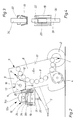
- Fig. 1
- eine Vorderansicht auf eine Rollballenpresse mit einer erfindungsgemäßen Ladeeinrichtung in in Strichlinie gezeichneter Position vor dem Einschieben in eine Abrollstation und in in Volllinie dargestellter Position in der Abrollstation,
- Fig. 2
- eine schematische Teilseitenansicht auf ein Vordergehäuse der Rollballenpresse mit einer Materialbahnrolle in der Abrollstation und mit einer Vorratsrolle auf der Ladeeinrichtung in eingeschobener Position in einer Vorratsstation der Rollballenpresse,
- Fig. 3
- eine Führungsschiene im Querschnitt mit aufgesetztem Laufrad der Ladeeinrichtung in der Abrollstation und
- Fig. 4
- eine Führungsschiene in Draufsicht mit einer Verriegelungsklinke zum Arretieren der Ladeeinrichtung in der Abroll- oder Vorratsstation.
Claims (11)
- Rollballenpresse für landwirtschaftliche Halmgüter mit einer außerhalb eines Pressraumes (10) an einem Pressraumgehäuse (5) parallel zu einer Umhüllvorrichtung (11) angeordneten Abrollstation (13) für eine Materialbahnrolle (14) und einer Ladeeinrichtung (18) für die Materialbahnrolle (14), dadurch gekennzeichnet, dass die Ladeeinrichtung (18) zusammen mit der Materialbahnrolle (14, 14a) in die Abrollstation (13) oder eine Vorratsstation (13a) bewegbar ist.
- Rollballenpresse nach Anspruch 1, dadurch gekennzeichnet, dass parallel zur Zylinderachse (17) des Pressraumes (10) angeordnete Führungen (19) vorgesehen sind, auf denen die Ladeeinrichtung (18) verschieb- oder verfahrbar ist.
- Rollballenpresse nach Anspruch 2, dadurch gekennzeichnet, dass die Führungen (19) im Bereich einer Seitenwand (8) der Rundballenpresse nach außen und unten abgewinkelt sind.
- Rollballenpresse nach einem der vorhergehenden Ansprüche, dadurch gekennzeichnet, dass Sicherungsmittel (22, 23) vorgesehen sind zum Arretieren der Ladeeinrichtung (18) in der Abroll-(13) oder Vorratsstation (13a).
- Rollballenpresse nach einem der vorhergehenden Ansprüche, dadurch gekennzeichnet, dass die Abrollstation (13) einen einfachen Behälter (15) zur Aufnahme einer Materialbahnrolle (14) aufweist und parallel dazu eine Vorratsstation (13a) angeordnet ist, in welche eine Vorratsrolle (14a) zusammen mit der Ladeeinrichtung (18) einschiebbar ist, wobei die Vorratsrolle (14a) leicht und einfach von der Vorratsstation (13a) in die Abrollstation (13) überführbar ist.
- Rollballenpresse nach einem der vorhergehenden Ansprüche, dadurch gekennzeichnet, dass die Ladeeinrichtung (18) um eine horizontale, rechtwinklig zur Zylinderachse (17) des Pressraumes (10) gelegene Achse verschwenkbar ist.
- Rollballenpresse nach einem der vorhergehenden Ansprüche, dadurch gekennzeichnet, dass die Ladeeinrichtung (18) als fahrbare Transporteinrichtung für die Materialbahnrolle (14, 14a) ausgestaltet ist.
- Rollballenpresse nach Anspruch 7, dadurch gekennzeichnet, dass die Ladeeinrichtung (18) leicht lös- und abnehmbar mit der Rollballenpresse verbunden ist, und dass im einschubseitigen Bereich der Seitenwand (8) der Rollballenpresse eine Halterung (21) vorgesehen ist, in welche die Ladeeinrichtung (18) gemeinsam mit einer Materialbahnrolle (14, 14a) leicht einhängbar ist.
- Rollballenpresse nach Anspruch 7 oder 8, dadurch gekennzeichnet, dass die Ladeeinrichtung (18) als Tragelement (24, 25, 28, 32) für die Materialbahnrolle (14, 14a) ausgebildet ist und Mittel (26, 27) vorgesehen sind, welche die Materialbahnrolle (14, 14a) wenigstens an den Stirnseiten gegen Wegrutschen in axialer Richtung halten.
- Rollballenpresse nach einem der Ansprüche 7 bis 9, dadurch gekennzeichnet, dass die Ladeeinrichtung (18) wenigstens einen Handgriff (29) zum Ziehen, einen Handgriff (32) zum Einschieben in die Abroll- (13) oder Vorratsstation (13a) und Laufräder (34) aufweist.
- Rollballenpresse nach einem oder mehreren der vorhergehenden Ansprüche, dadurch gekennzeichnet, dass hydraulische, mechanische, elektrische und/oder pneumatische Antriebe zum Überführen der Ladeeinrichtung (18) in die Abroll- (13) und/oder Vorratsstation (13a) vorgesehen sind.
Applications Claiming Priority (2)
| Application Number | Priority Date | Filing Date | Title |
|---|---|---|---|
| DE10004563A DE10004563A1 (de) | 2000-02-02 | 2000-02-02 | Rollballenpresse für landwirtschaftliche Halmgüter |
| DE10004563 | 2000-02-02 |
Publications (2)
| Publication Number | Publication Date |
|---|---|
| EP1121850A1 true EP1121850A1 (de) | 2001-08-08 |
| EP1121850B1 EP1121850B1 (de) | 2009-04-08 |
Family
ID=7629592
Family Applications (1)
| Application Number | Title | Priority Date | Filing Date |
|---|---|---|---|
| EP01101883A Expired - Lifetime EP1121850B1 (de) | 2000-02-02 | 2001-01-27 | Rollballenpresse für landwirtschaftliche Halmgüter |
Country Status (3)
| Country | Link |
|---|---|
| EP (1) | EP1121850B1 (de) |
| AT (1) | ATE427649T1 (de) |
| DE (2) | DE10004563A1 (de) |
Cited By (7)
| Publication number | Priority date | Publication date | Assignee | Title |
|---|---|---|---|---|
| EP1602270A1 (de) * | 2004-06-04 | 2005-12-07 | Welger Maschinenfabrik GmbH | Rundballenpresse für landwirtschaftliche Halmgüter |
| EP2407024A3 (de) * | 2010-07-16 | 2013-10-16 | Maschinenfabrik Bernard Krone GmbH | Ballenpresse |
| EP2932820A1 (de) * | 2014-04-18 | 2015-10-21 | CNH Industrial Belgium nv | Indizierendes wickelsystem und tragesysteme |
| DE102017122130A1 (de) | 2017-09-25 | 2019-03-28 | Usines Claas France S.A.S. | Landwirtschaftliche Rundballenpresse sowie Verfahren zur Ladung einer Zuführeinrichtung einer Rundballenpresse |
| EP3590327A1 (de) | 2018-07-05 | 2020-01-08 | CNH Industrial Belgium N.V. | Ballenpresse |
| EP3721699A1 (de) * | 2019-04-12 | 2020-10-14 | Deere & Company | Ballenwickelvorrichtung für eine ballenpresse, beladehilfe und ballenpresse |
| US12232453B2 (en) | 2022-05-18 | 2025-02-25 | Agco Corporation | Agricultural baler |
Families Citing this family (2)
| Publication number | Priority date | Publication date | Assignee | Title |
|---|---|---|---|---|
| DE102004027307A1 (de) * | 2004-06-04 | 2005-12-22 | Welger Maschinenfabrik Gmbh | Vorrichtung zum Umhüllen von Erntegutballen |
| NL2014872B1 (en) | 2015-05-28 | 2016-12-30 | Forage Innovations Bv | Wrapping device for wrapping a bale in a bale forming chamber. |
Citations (5)
| Publication number | Priority date | Publication date | Assignee | Title |
|---|---|---|---|---|
| US4569439A (en) * | 1982-07-21 | 1986-02-11 | Claas Ohg | Round bales of agricultural blade crops |
| US4956959A (en) * | 1989-06-23 | 1990-09-18 | Deere & Company | Housing for holding a supply roll of large round bale wrap material |
| DE9211541U1 (de) * | 1992-08-27 | 1992-11-05 | Maschinenfabriken Bernard Krone Gmbh, 4441 Spelle | Rundballenpresse für landwirtschaftliches Erntegut |
| US5181368A (en) * | 1991-12-17 | 1993-01-26 | Deere & Company | Housing for holding a supply roll of large round bale wrap material |
| DE19711164A1 (de) | 1997-03-18 | 1998-09-24 | Claas Ohg | Rollballenpresse für landwirtschaftliches Erntegut |
Family Cites Families (1)
| Publication number | Priority date | Publication date | Assignee | Title |
|---|---|---|---|---|
| US4691503A (en) * | 1986-07-08 | 1987-09-08 | Deere & Company | Housing for holding a supply roll of large round bale wrap material |
-
2000
- 2000-02-02 DE DE10004563A patent/DE10004563A1/de not_active Withdrawn
-
2001
- 2001-01-27 AT AT01101883T patent/ATE427649T1/de not_active IP Right Cessation
- 2001-01-27 EP EP01101883A patent/EP1121850B1/de not_active Expired - Lifetime
- 2001-01-27 DE DE50114810T patent/DE50114810D1/de not_active Expired - Lifetime
Patent Citations (5)
| Publication number | Priority date | Publication date | Assignee | Title |
|---|---|---|---|---|
| US4569439A (en) * | 1982-07-21 | 1986-02-11 | Claas Ohg | Round bales of agricultural blade crops |
| US4956959A (en) * | 1989-06-23 | 1990-09-18 | Deere & Company | Housing for holding a supply roll of large round bale wrap material |
| US5181368A (en) * | 1991-12-17 | 1993-01-26 | Deere & Company | Housing for holding a supply roll of large round bale wrap material |
| DE9211541U1 (de) * | 1992-08-27 | 1992-11-05 | Maschinenfabriken Bernard Krone Gmbh, 4441 Spelle | Rundballenpresse für landwirtschaftliches Erntegut |
| DE19711164A1 (de) | 1997-03-18 | 1998-09-24 | Claas Ohg | Rollballenpresse für landwirtschaftliches Erntegut |
Cited By (9)
| Publication number | Priority date | Publication date | Assignee | Title |
|---|---|---|---|---|
| EP1602270A1 (de) * | 2004-06-04 | 2005-12-07 | Welger Maschinenfabrik GmbH | Rundballenpresse für landwirtschaftliche Halmgüter |
| EP2407024A3 (de) * | 2010-07-16 | 2013-10-16 | Maschinenfabrik Bernard Krone GmbH | Ballenpresse |
| EP2932820A1 (de) * | 2014-04-18 | 2015-10-21 | CNH Industrial Belgium nv | Indizierendes wickelsystem und tragesysteme |
| DE102017122130A1 (de) | 2017-09-25 | 2019-03-28 | Usines Claas France S.A.S. | Landwirtschaftliche Rundballenpresse sowie Verfahren zur Ladung einer Zuführeinrichtung einer Rundballenpresse |
| EP3590327A1 (de) | 2018-07-05 | 2020-01-08 | CNH Industrial Belgium N.V. | Ballenpresse |
| BE1026444B1 (nl) * | 2018-07-05 | 2020-02-04 | Cnh Ind Belgium Nv | Balenpers |
| US11116141B2 (en) | 2018-07-05 | 2021-09-14 | Cnh Industrial America Llc | Baler |
| EP3721699A1 (de) * | 2019-04-12 | 2020-10-14 | Deere & Company | Ballenwickelvorrichtung für eine ballenpresse, beladehilfe und ballenpresse |
| US12232453B2 (en) | 2022-05-18 | 2025-02-25 | Agco Corporation | Agricultural baler |
Also Published As
| Publication number | Publication date |
|---|---|
| DE10004563A1 (de) | 2001-08-09 |
| DE50114810D1 (de) | 2009-05-20 |
| EP1121850B1 (de) | 2009-04-08 |
| ATE427649T1 (de) | 2009-04-15 |
Similar Documents
| Publication | Publication Date | Title |
|---|---|---|
| EP1099366B1 (de) | Hüllmittelzufuhrvorrichtung | |
| DE69707050T2 (de) | Ernteaufsammeleinrichtung | |
| DE19731520C2 (de) | Vorrichtung zum Pressen und Umwickeln von Rundballen | |
| DE19711164A1 (de) | Rollballenpresse für landwirtschaftliches Erntegut | |
| DE10006384A1 (de) | Rundballenpresse | |
| EP0092077A1 (de) | Antriebsvorrichtung für die Welle einer mobilen Einrichtung | |
| DE3424567C2 (de) | ||
| DE2851035A1 (de) | Maschine zum aufwickeln von faserigem erntegut zu grossen rundballen | |
| DE3443666A1 (de) | Ballenpresse | |
| EP0935915A1 (de) | Wickelvorrichtung einer Presse mit einer Materialrolle und einer Vorratsrolle | |
| EP3785521B1 (de) | Landwirtschaftliche ballenpresse mit einer bindung und verfahren zum warten der ballenpresse | |
| DE3501062C2 (de) | ||
| DE2530249A1 (de) | Wickelballenpresse | |
| DE102004027307A1 (de) | Vorrichtung zum Umhüllen von Erntegutballen | |
| DE19959574A1 (de) | Ballenpresse | |
| EP1186225B1 (de) | Kombination aus einer Presse, einem Wickelgerät und einem diese aufnehmenden Fahrgestell | |
| EP1121850B1 (de) | Rollballenpresse für landwirtschaftliche Halmgüter | |
| DE69901601T2 (de) | Ballensammler mit schwenkbare hintere rollenwand | |
| DE69521457T2 (de) | Ballen-Lade-Wagen um Ballen an eine Wickelvorrichtung abzugeben | |
| DE2947442C2 (de) | ||
| EP0350514A1 (de) | Landwirtschaftliche Aufsammelpresse | |
| EP1129611B1 (de) | Rollballenpresse für landwirtschaftliche Halmgüter | |
| EP1602270B1 (de) | Rundballenpresse für landwirtschaftliche Halmgüter | |
| DE69723099T2 (de) | Grossballenhandlungsgerät | |
| DE2530320A1 (de) | Bindevorrichtung fuer wickelballenpressen |
Legal Events
| Date | Code | Title | Description |
|---|---|---|---|
| PUAI | Public reference made under article 153(3) epc to a published international application that has entered the european phase |
Free format text: ORIGINAL CODE: 0009012 |
|
| AK | Designated contracting states |
Kind code of ref document: A1 Designated state(s): AT DE FR GB IT NL |
|
| AX | Request for extension of the european patent |
Free format text: AL;LT;LV;MK;RO;SI |
|
| RAP1 | Party data changed (applicant data changed or rights of an application transferred) |
Owner name: LELY MASCHINENFABRIK GMBH |
|
| 17P | Request for examination filed |
Effective date: 20020208 |
|
| AKX | Designation fees paid |
Free format text: AT DE FR GB IT NL |
|
| RAP1 | Party data changed (applicant data changed or rights of an application transferred) |
Owner name: WELGER MASCHINENFABRIK GMBH |
|
| 17Q | First examination report despatched |
Effective date: 20060712 |
|
| GRAP | Despatch of communication of intention to grant a patent |
Free format text: ORIGINAL CODE: EPIDOSNIGR1 |
|
| GRAP | Despatch of communication of intention to grant a patent |
Free format text: ORIGINAL CODE: EPIDOSNIGR1 |
|
| GRAS | Grant fee paid |
Free format text: ORIGINAL CODE: EPIDOSNIGR3 |
|
| GRAA | (expected) grant |
Free format text: ORIGINAL CODE: 0009210 |
|
| AK | Designated contracting states |
Kind code of ref document: B1 Designated state(s): AT DE FR GB IT NL |
|
| REG | Reference to a national code |
Ref country code: GB Ref legal event code: FG4D Free format text: NOT ENGLISH |
|
| REF | Corresponds to: |
Ref document number: 50114810 Country of ref document: DE Date of ref document: 20090520 Kind code of ref document: P |
|
| PLBE | No opposition filed within time limit |
Free format text: ORIGINAL CODE: 0009261 |
|
| STAA | Information on the status of an ep patent application or granted ep patent |
Free format text: STATUS: NO OPPOSITION FILED WITHIN TIME LIMIT |
|
| 26N | No opposition filed |
Effective date: 20100111 |
|
| PG25 | Lapsed in a contracting state [announced via postgrant information from national office to epo] |
Ref country code: IT Free format text: LAPSE BECAUSE OF FAILURE TO SUBMIT A TRANSLATION OF THE DESCRIPTION OR TO PAY THE FEE WITHIN THE PRESCRIBED TIME-LIMIT Effective date: 20090408 |
|
| PG25 | Lapsed in a contracting state [announced via postgrant information from national office to epo] |
Ref country code: AT Free format text: LAPSE BECAUSE OF NON-PAYMENT OF DUE FEES Effective date: 20100127 |
|
| REG | Reference to a national code |
Ref country code: NL Ref legal event code: TD Effective date: 20140418 |
|
| REG | Reference to a national code |
Ref country code: FR Ref legal event code: CD Owner name: LELY VERMEER MASCHINENFABRIK GMBH, DE Effective date: 20140507 |
|
| REG | Reference to a national code |
Ref country code: DE Ref legal event code: R081 Ref document number: 50114810 Country of ref document: DE Owner name: LELY VERMEER MASCHINENFABRIK GMBH, DE Free format text: FORMER OWNER: WELGER MASCHINENFABRIK GMBH, 38304 WOLFENBUETTEL, DE Effective date: 20140502 Ref country code: DE Ref legal event code: R081 Ref document number: 50114810 Country of ref document: DE Owner name: LELY MASCHINENFABRIK GMBH, DE Free format text: FORMER OWNER: WELGER MASCHINENFABRIK GMBH, 38304 WOLFENBUETTEL, DE Effective date: 20140502 Ref country code: DE Ref legal event code: R081 Ref document number: 50114810 Country of ref document: DE Owner name: FORAGE COMPANY B.V., NL Free format text: FORMER OWNER: WELGER MASCHINENFABRIK GMBH, 38304 WOLFENBUETTEL, DE Effective date: 20140502 |
|
| PGFP | Annual fee paid to national office [announced via postgrant information from national office to epo] |
Ref country code: NL Payment date: 20150126 Year of fee payment: 15 |
|
| PGFP | Annual fee paid to national office [announced via postgrant information from national office to epo] |
Ref country code: GB Payment date: 20150127 Year of fee payment: 15 |
|
| REG | Reference to a national code |
Ref country code: FR Ref legal event code: PLFP Year of fee payment: 16 |
|
| GBPC | Gb: european patent ceased through non-payment of renewal fee |
Effective date: 20160127 |
|
| REG | Reference to a national code |
Ref country code: NL Ref legal event code: MM Effective date: 20160201 |
|
| PG25 | Lapsed in a contracting state [announced via postgrant information from national office to epo] |
Ref country code: GB Free format text: LAPSE BECAUSE OF NON-PAYMENT OF DUE FEES Effective date: 20160127 |
|
| PG25 | Lapsed in a contracting state [announced via postgrant information from national office to epo] |
Ref country code: NL Free format text: LAPSE BECAUSE OF NON-PAYMENT OF DUE FEES Effective date: 20160201 |
|
| REG | Reference to a national code |
Ref country code: FR Ref legal event code: PLFP Year of fee payment: 17 |
|
| REG | Reference to a national code |
Ref country code: DE Ref legal event code: R081 Ref document number: 50114810 Country of ref document: DE Owner name: LELY MASCHINENFABRIK GMBH, DE Free format text: FORMER OWNER: LELY VERMEER MASCHINENFABRIK GMBH, 38304 WOLFENBUETTEL, DE Ref country code: DE Ref legal event code: R081 Ref document number: 50114810 Country of ref document: DE Owner name: FORAGE COMPANY B.V., NL Free format text: FORMER OWNER: LELY VERMEER MASCHINENFABRIK GMBH, 38304 WOLFENBUETTEL, DE |
|
| PGFP | Annual fee paid to national office [announced via postgrant information from national office to epo] |
Ref country code: DE Payment date: 20170125 Year of fee payment: 17 Ref country code: FR Payment date: 20170125 Year of fee payment: 17 |
|
| REG | Reference to a national code |
Ref country code: DE Ref legal event code: R081 Ref document number: 50114810 Country of ref document: DE Owner name: FORAGE COMPANY B.V., NL Free format text: FORMER OWNER: LELY MASCHINENFABRIK GMBH, 38304 WOLFENBUETTEL, DE |
|
| REG | Reference to a national code |
Ref country code: DE Ref legal event code: R119 Ref document number: 50114810 Country of ref document: DE |
|
| PG25 | Lapsed in a contracting state [announced via postgrant information from national office to epo] |
Ref country code: DE Free format text: LAPSE BECAUSE OF NON-PAYMENT OF DUE FEES Effective date: 20180801 Ref country code: FR Free format text: LAPSE BECAUSE OF NON-PAYMENT OF DUE FEES Effective date: 20180131 |
|
| REG | Reference to a national code |
Ref country code: FR Ref legal event code: ST Effective date: 20180928 |