EP1121194B1 - Device for mixing two pasty materials, especially for mixing a dental impression material with a catalyst material - Google Patents
Device for mixing two pasty materials, especially for mixing a dental impression material with a catalyst material Download PDFInfo
- Publication number
- EP1121194B1 EP1121194B1 EP99953812A EP99953812A EP1121194B1 EP 1121194 B1 EP1121194 B1 EP 1121194B1 EP 99953812 A EP99953812 A EP 99953812A EP 99953812 A EP99953812 A EP 99953812A EP 1121194 B1 EP1121194 B1 EP 1121194B1
- Authority
- EP
- European Patent Office
- Prior art keywords
- housing
- mixer
- mixing
- axis
- tubular portion
- Prior art date
- Legal status (The legal status is an assumption and is not a legal conclusion. Google has not performed a legal analysis and makes no representation as to the accuracy of the status listed.)
- Expired - Lifetime
Links
Images


Classifications
-
- B—PERFORMING OPERATIONS; TRANSPORTING
- B05—SPRAYING OR ATOMISING IN GENERAL; APPLYING FLUENT MATERIALS TO SURFACES, IN GENERAL
- B05C—APPARATUS FOR APPLYING FLUENT MATERIALS TO SURFACES, IN GENERAL
- B05C17/00—Hand tools or apparatus using hand held tools, for applying liquids or other fluent materials to, for spreading applied liquids or other fluent materials on, or for partially removing applied liquids or other fluent materials from, surfaces
- B05C17/005—Hand tools or apparatus using hand held tools, for applying liquids or other fluent materials to, for spreading applied liquids or other fluent materials on, or for partially removing applied liquids or other fluent materials from, surfaces for discharging material from a reservoir or container located in or on the hand tool through an outlet orifice by pressure without using surface contacting members like pads or brushes
- B05C17/00553—Hand tools or apparatus using hand held tools, for applying liquids or other fluent materials to, for spreading applied liquids or other fluent materials on, or for partially removing applied liquids or other fluent materials from, surfaces for discharging material from a reservoir or container located in or on the hand tool through an outlet orifice by pressure without using surface contacting members like pads or brushes with means allowing the stock of material to consist of at least two different components
-
- A—HUMAN NECESSITIES
- A61—MEDICAL OR VETERINARY SCIENCE; HYGIENE
- A61C—DENTISTRY; APPARATUS OR METHODS FOR ORAL OR DENTAL HYGIENE
- A61C5/00—Filling or capping teeth
- A61C5/60—Devices specially adapted for pressing or mixing capping or filling materials, e.g. amalgam presses
- A61C5/62—Applicators, e.g. syringes or guns
- A61C5/64—Applicators, e.g. syringes or guns for multi-component compositions
-
- A—HUMAN NECESSITIES
- A61—MEDICAL OR VETERINARY SCIENCE; HYGIENE
- A61C—DENTISTRY; APPARATUS OR METHODS FOR ORAL OR DENTAL HYGIENE
- A61C9/00—Impression cups, i.e. impression trays; Impression methods
- A61C9/0026—Syringes or guns for injecting impression material; Mixing impression material for immediate use
-
- B—PERFORMING OPERATIONS; TRANSPORTING
- B01—PHYSICAL OR CHEMICAL PROCESSES OR APPARATUS IN GENERAL
- B01F—MIXING, e.g. DISSOLVING, EMULSIFYING OR DISPERSING
- B01F27/00—Mixers with rotary stirring devices in fixed receptacles; Kneaders
- B01F27/05—Stirrers
-
- B—PERFORMING OPERATIONS; TRANSPORTING
- B01—PHYSICAL OR CHEMICAL PROCESSES OR APPARATUS IN GENERAL
- B01F—MIXING, e.g. DISSOLVING, EMULSIFYING OR DISPERSING
- B01F27/00—Mixers with rotary stirring devices in fixed receptacles; Kneaders
- B01F27/05—Stirrers
- B01F27/07—Stirrers characterised by their mounting on the shaft
- B01F27/072—Stirrers characterised by their mounting on the shaft characterised by the disposition of the stirrers with respect to the rotating axis
- B01F27/0724—Stirrers characterised by their mounting on the shaft characterised by the disposition of the stirrers with respect to the rotating axis directly mounted on the rotating axis
-
- B—PERFORMING OPERATIONS; TRANSPORTING
- B05—SPRAYING OR ATOMISING IN GENERAL; APPLYING FLUENT MATERIALS TO SURFACES, IN GENERAL
- B05C—APPARATUS FOR APPLYING FLUENT MATERIALS TO SURFACES, IN GENERAL
- B05C17/00—Hand tools or apparatus using hand held tools, for applying liquids or other fluent materials to, for spreading applied liquids or other fluent materials on, or for partially removing applied liquids or other fluent materials from, surfaces
- B05C17/005—Hand tools or apparatus using hand held tools, for applying liquids or other fluent materials to, for spreading applied liquids or other fluent materials on, or for partially removing applied liquids or other fluent materials from, surfaces for discharging material from a reservoir or container located in or on the hand tool through an outlet orifice by pressure without using surface contacting members like pads or brushes
- B05C17/00503—Details of the outlet element
- B05C17/00506—Means for connecting the outlet element to, or for disconnecting it from, the hand tool or its container
-
- B—PERFORMING OPERATIONS; TRANSPORTING
- B05—SPRAYING OR ATOMISING IN GENERAL; APPLYING FLUENT MATERIALS TO SURFACES, IN GENERAL
- B05C—APPARATUS FOR APPLYING FLUENT MATERIALS TO SURFACES, IN GENERAL
- B05C17/00—Hand tools or apparatus using hand held tools, for applying liquids or other fluent materials to, for spreading applied liquids or other fluent materials on, or for partially removing applied liquids or other fluent materials from, surfaces
- B05C17/005—Hand tools or apparatus using hand held tools, for applying liquids or other fluent materials to, for spreading applied liquids or other fluent materials on, or for partially removing applied liquids or other fluent materials from, surfaces for discharging material from a reservoir or container located in or on the hand tool through an outlet orifice by pressure without using surface contacting members like pads or brushes
- B05C17/00503—Details of the outlet element
- B05C17/00516—Shape or geometry of the outlet orifice or the outlet element
-
- B—PERFORMING OPERATIONS; TRANSPORTING
- B05—SPRAYING OR ATOMISING IN GENERAL; APPLYING FLUENT MATERIALS TO SURFACES, IN GENERAL
- B05C—APPARATUS FOR APPLYING FLUENT MATERIALS TO SURFACES, IN GENERAL
- B05C17/00—Hand tools or apparatus using hand held tools, for applying liquids or other fluent materials to, for spreading applied liquids or other fluent materials on, or for partially removing applied liquids or other fluent materials from, surfaces
- B05C17/005—Hand tools or apparatus using hand held tools, for applying liquids or other fluent materials to, for spreading applied liquids or other fluent materials on, or for partially removing applied liquids or other fluent materials from, surfaces for discharging material from a reservoir or container located in or on the hand tool through an outlet orifice by pressure without using surface contacting members like pads or brushes
- B05C17/00583—Hand tools or apparatus using hand held tools, for applying liquids or other fluent materials to, for spreading applied liquids or other fluent materials on, or for partially removing applied liquids or other fluent materials from, surfaces for discharging material from a reservoir or container located in or on the hand tool through an outlet orifice by pressure without using surface contacting members like pads or brushes the container for the material to be dispensed being deformable
-
- B—PERFORMING OPERATIONS; TRANSPORTING
- B05—SPRAYING OR ATOMISING IN GENERAL; APPLYING FLUENT MATERIALS TO SURFACES, IN GENERAL
- B05C—APPARATUS FOR APPLYING FLUENT MATERIALS TO SURFACES, IN GENERAL
- B05C17/00—Hand tools or apparatus using hand held tools, for applying liquids or other fluent materials to, for spreading applied liquids or other fluent materials on, or for partially removing applied liquids or other fluent materials from, surfaces
- B05C17/005—Hand tools or apparatus using hand held tools, for applying liquids or other fluent materials to, for spreading applied liquids or other fluent materials on, or for partially removing applied liquids or other fluent materials from, surfaces for discharging material from a reservoir or container located in or on the hand tool through an outlet orifice by pressure without using surface contacting members like pads or brushes
- B05C17/00586—Means, generally located near the nozzle, for piercing or perforating the front part of a cartridge
-
- B—PERFORMING OPERATIONS; TRANSPORTING
- B05—SPRAYING OR ATOMISING IN GENERAL; APPLYING FLUENT MATERIALS TO SURFACES, IN GENERAL
- B05C—APPARATUS FOR APPLYING FLUENT MATERIALS TO SURFACES, IN GENERAL
- B05C17/00—Hand tools or apparatus using hand held tools, for applying liquids or other fluent materials to, for spreading applied liquids or other fluent materials on, or for partially removing applied liquids or other fluent materials from, surfaces
- B05C17/005—Hand tools or apparatus using hand held tools, for applying liquids or other fluent materials to, for spreading applied liquids or other fluent materials on, or for partially removing applied liquids or other fluent materials from, surfaces for discharging material from a reservoir or container located in or on the hand tool through an outlet orifice by pressure without using surface contacting members like pads or brushes
- B05C17/00596—The liquid or other fluent material being supplied from a rigid removable cartridge having no active dispensing means, i.e. the cartridge requiring cooperation with means of the handtool to expel the material
-
- B—PERFORMING OPERATIONS; TRANSPORTING
- B01—PHYSICAL OR CHEMICAL PROCESSES OR APPARATUS IN GENERAL
- B01F—MIXING, e.g. DISSOLVING, EMULSIFYING OR DISPERSING
- B01F2101/00—Mixing characterised by the nature of the mixed materials or by the application field
- B01F2101/2305—Mixers of the two-component package type, i.e. where at least two components are separately stored, and are mixed in the moment of application
-
- B—PERFORMING OPERATIONS; TRANSPORTING
- B01—PHYSICAL OR CHEMICAL PROCESSES OR APPARATUS IN GENERAL
- B01F—MIXING, e.g. DISSOLVING, EMULSIFYING OR DISPERSING
- B01F33/00—Other mixers; Mixing plants; Combinations of mixers
- B01F33/50—Movable or transportable mixing devices or plants
- B01F33/501—Movable mixing devices, i.e. readily shifted or displaced from one place to another, e.g. portable during use
- B01F33/5011—Movable mixing devices, i.e. readily shifted or displaced from one place to another, e.g. portable during use portable during use, e.g. hand-held
Definitions
- the invention relates to a device for mixing two pasty Masses, which are in particular a dental impression material and a Catalyst mass to accelerate the polymerization of the dental impression material is.
- the device according to the invention is placed on the two outlet connections Discharge device attached, by means of which by applying pressure the pasty masses are introduced into the mixing device and after Mixing in the mixing device can be output as a mixture.
- a dynamic mixer is known from EP-A-0 492 412 known.
- This known device has an essentially tubular one Mixer housing with a mixer shaft rotatably arranged therein.
- the Mixer shaft has a plurality of radially projecting web-shaped Mixer elements which, when the mixer shaft is driven, for a deflection of the mass flows and thus the two pasty masses mixed together.
- the pasty masses pass through a radial Front wall at the rear end of the mixer housing into this.
- the end wall has two inlet connections which are connected to the Outlet nozzle of a device for dispensing the pasty masses be plugged on.
- the known mixer has a discharge device projecting from the mixer shaft Wiper elements on the inside of the rear end wall move long and pasty material arriving via the inlet connection Transport side. This via the one inlet connector into the interior of the housing pasty material introduced is at least partially in Transports circumferential direction and thus reaches the area of the other Inlet port where, when the dynamic mixer is not driven, back contamination up to the inlet nozzle and further into the this connected outlet port of the associated discharge device can come.
- the invention has for its object a device for mixing to create two pasty masses, in which the risk of Recontamination is reduced.
- the invention provides a device for Mixing two pasty masses according to claim 1 proposed.
- the paste to be mixed is fed radially into the substantially tubular section of the mixer housing into it.
- the tubular section of the housing is two in particular provided diametrically opposite radial inlet openings.
- the at least one Deflection element around a substantially sawtooth-shaped wedge that is bent runs around the axis of the mixer shaft.
- This deflecting element acts like a screw conveyor in a screw pump and ensures that pasty material directly in the axial direction from the inlet openings is discharged in the direction of the outlet opening. With that Back contamination reliably prevented, because that is always the least a deflection element for the axial transport through the inlet openings in the tubular section of the mixer housing passing pasty masses supported.
- the deflection element can have a wedge shape.
- the deflecting element can be used as one to form a helical web extending around the axis; in this exemplary embodiment, the deflecting element thus has the shape of a Thread on.
- Such rotating webs are from screw pumps and Screw conveyors are known.
- each deflecting element arranged on the axis, the are expediently arranged diametrically opposite one another.
- This Deflection elements or each deflection element preferably extends over an angular range of 180 ° to 90 °.
- the housing has on its rear end on an insert directed transversely to the axis, of which two Protrude inlet connection.
- the insert is in a conical expanded, adjoining the tubular section Housing section of the mixer and has two channels, which differ from the Extend inlet port from. These two channels are angled radially into a central cylindrical recess on the inside of the Insert part, of which the axis of the mixer shaft with the at least one Deflection element is added. So it forms the cylindrical one Receiving recess of the insert part of a portion of the tubular Housing section of the mixer.
- mixer elements are located within the tubular housing section between the radial inlet openings and the axial outlet opening several mixer elements, the kind of radial Webs protrude from the axis and close to the inner surface of the tubular Range section.
- These mixer elements are within several Radial planes projecting from the shaft and lead to a Deflection of the axially extending through the housing Mass flows. This leads to the desired mixing.
- the Mixing effect is enhanced when these mixer elements due to their radial orientation, the direct current between the Inlet openings and the outlet opening prevent it from going over a larger one Angle range, for example, extend 90 °. This can be realized be that adjacent mixer elements by a rotating Section are interconnected.
- the mixer shaft has additional flexibility Scraper elements, which due to their flexibility or at least their flexible free ends spaced from the axis Brush along the inside wall of the tubular housing.
- Fig. 1 is a discharge device 10 for two to be mixed together pasty components shown in side view.
- the device 10 comprises a pressing part 12 and a mixer part 14, the pressing part 12 two Pressure vessel 16, 18 for receiving two containing the pasty masses Tubular bag 20, 22 has.
- At the front ends 24.26 of the Pressure vessels 16, 18 have these outlet ports 28, 30, via which Applying pressure to the rear end of the tubular bag 20, 22 Content is deployed.
- the pressurization of the tubular bags 20, 22 takes place by means of pressure stamps 32, 34 which are motor-driven, which is here is not shown in detail.
- a dynamic mixer 36 is attached to the outlet port 28, 30 based on the figures 2 to 7 will be described in more detail below. All in general it can be said about this dynamic mixer 36 that its Mixer shaft 38 is motor-driven. For this purpose, the Mixer shaft 38 can be coupled to a drive rod 40, which is also by one Motor, not shown, is driven in rotation.
- the details of the dynamic mixer 36 are particularly based on Fig. 2 clearly.
- the mixer 36 has a housing 42 which is essentially one cylindrical or tubular section 44 with a flared End section 46 at the rear end facing the extrusion tool 12 48 and has a tapered front end 50.
- the tapered end 50 is as Exhaust port formed and defines the outlet opening 52 for the Mixture of materials, while at the rear end 48 of the housing 42 two Inlet ports 54,56 are arranged which on the outlet ports 28,30 of Squeezing tool 12 can be plugged.
- the drive rod 40 is also connected to this opening the mixer shaft 38 can be coupled.
- the inlet ports 54, 56 and the opening 58 are in an insert part 62 formed at the rear end 48 of the housing 42 in its conical Expansion section 46 is inserted. Starting from the inlet port 54,56 extend through the insert part 62 two channels 64,66, which under Deflection opens in radial openings 68.70. These inlet openings 68.70 are radial with respect to the cylindrical portion 44 of the mixer housing 42 arranged. The two pasty components are in via the channels 64,66 the dynamic mixer 36 transported into, where it is then in radial Impact direction on the mixer shaft 38.
- the insert part 62 has a central substantially cylindrical receiving recess 69 on the is arranged concentrically to the opening 58 and into which the mixer shaft 38 is inserted.
- the inlet openings 68, 70 are introduced in the cylindrical wall 71 of the receiving recess 69 .
- the channels 64,66 formed in this area. These channels 64, 66 are grooves open at the top or recesses formed together with the substantially conical flared housing section 46 form the channels closed on all sides.
- the mixer shaft 38 has a rotatably mounted axis 72, of which in a A large number of radial planes each have four web-shaped mixer elements 74 in protrude substantially radially.
- the exact arrangement of these mixer elements 74 results from the sectional view according to FIG. 4. It can be seen that the a circumferential boundary side edges of the Mixer elements 74 essentially tangential to the peripheral surface of axis 72 run.
- there are four per radial plane Mixer elements 74 are provided, which according to FIG. 2 are close to the inner surface 76 of the cylindrical housing portion 44 range.
- the mixer element 78 'according to 7 thus has a larger section in a central circumferential section to the inner surface 76 of the cylindrical housing section 44.
- the mixer shaft 38 has in the radial Inlet openings 68,70 two deflecting elements 80, which in the manner of a Screw conveyor are formed.
- the deflection elements 80 are as sawtooth-shaped wedges formed, which are about 90 ° about the axis 72 of the Extend mixer shaft 38 around.
- the deflection elements 80 have an in Circumferential direction increasing deflection surface 82, which in the direction of Outlet end 52 of dynamic mixer 36 faces and angled to a radial to the plane running axis 72.
- deflection elements 80 run So in sections helical and ensure an axial Movement component of the pasty mass flows. With this they support Deflection elements 80 the removal of pasty mass, which from the Inlet openings 68,70 penetrates into the cylindrical housing section 44. This supportive and thus reinforcing removal of the pasty masses in axial direction reduces the risk of contamination of the two pasty Masses, i.e. the unwanted mixing or recontamination of the two pasty masses via the inlet openings 68.70 into the channels 64.66 and if necessary continue to the outlet port 28,30. Because if it's in this Contamination and polymerisation, due to the blockage of the outlet port 28, 30, this can be done if necessary residual material still in the tubular bags 20, 22 no longer deliver.
- mixer elements 78 and 78 ' the two adjacent mixer elements 74 with each other connect and also offset in this case by 90 ° from the radial plane Radial plane are arranged.
- Mixer elements 84 and mixer elements 78 and 78 ' are thus along a helix around axis 72 evenly distributed. Both types of mixer elements are suitable excellent for a homogeneous mixing of the pasty masses in the also dynamic mixer 36 to be referred to as a continuous mixer.
Abstract
Description
Die Erfindung betrifft eine Vorrichtung zum Vermischen zweier pastöser Massen, bei denen es sich insbesondere um eine Dental-Abformmasse und eine Katalysatormasse zur Beschleunigung der Polymerisation der Dental-Abformmasse handelt.The invention relates to a device for mixing two pasty Masses, which are in particular a dental impression material and a Catalyst mass to accelerate the polymerization of the dental impression material is.
Die erfindungsgemäße Vorrichtung wird auf die beiden Auslassstutzen einer Austragvorrichtung aufgesteckt, mittels derer durch Aufbringen von Druck auf die pastösen Massen diese in die Mischvorrichtung eingebracht und nach dem Vermischen in der Mischvorrichtung aus dieser als Gemisch ausgegeben werden.The device according to the invention is placed on the two outlet connections Discharge device attached, by means of which by applying pressure the pasty masses are introduced into the mixing device and after Mixing in the mixing device can be output as a mixture.
In einer Vielzahl von technischen Anwendungsgebieten ist es erforderlich, zwei getrennt gelagerte pastöse Massen in vermischter Form zu applizieren. Hierbei bedient man sich entweder dynamischer oder statischer Durchlaufmischer, die während des Fließens der pastösen Massen durch ein Mischergehäuse die Massen untereinander vermischen. Ein dynamischer Mischer ist aus EP-A-0 492 412 bekannt. Diese bekannte Vorrichtung weist ein im wesentlichen rohrförmiges Mischergehäuse mit einer darin drehbar angeordneten Mischerwelle auf. Die Mischerwelle weist eine Vielzahl von radial abstehenden stegförmigen Mischerelementen auf, die dann, wenn die Mischerwelle angetrieben wird, für eine Umlenkung der Massenströme sorgt und damit die beiden pastösen Massen miteinander vermischt. Die pastösen Massen gelangen über eine radiale Stirnwand am hinteren Ende des Mischergehäuses in dieses hinein. Die Stirnwand weist zu diesem Zweck zwei Einlassstutzen auf, die auf die Auslassstutzen einer Vorrichtung zum Ausbringen der pastösen Massen aufgesteckt werden. In a variety of technical applications, two are required to apply separately stored pasty masses in mixed form. in this connection one uses either dynamic or static continuous mixers that the masses as the pasty masses flow through a mixer housing mix with each other. A dynamic mixer is known from EP-A-0 492 412 known. This known device has an essentially tubular one Mixer housing with a mixer shaft rotatably arranged therein. The Mixer shaft has a plurality of radially projecting web-shaped Mixer elements which, when the mixer shaft is driven, for a deflection of the mass flows and thus the two pasty masses mixed together. The pasty masses pass through a radial Front wall at the rear end of the mixer housing into this. The For this purpose, the end wall has two inlet connections which are connected to the Outlet nozzle of a device for dispensing the pasty masses be plugged on.
Zur Vermeidung von Rückkontaminationen in die Auslassstutzen der Austragvorrichtung weist der bekannte Mischer von der Mischerwelle abstehende Abstreiferelemente auf, die auf der Innenseite der rückwärtigen Stirnwand sich lang bewegen und über die Einlassstutzen ankommendes pastöses Material zur Seite transportieren. Das über den einen Einlassstutzen in das Gehäuseinnere eingebrachte pastöse Material wird durch diese Abstreifer zumindest teilweise in Umfangsrichtung transportiert und gelangt damit in den Bereich des anderen Einlassstutzens, wo es dann, wenn der dynamische Mischer nicht angetrieben ist, zu einer Rückkontamination bis in den Einlassstutzen und weiter in den mit diesem verbundenen Auslassstutzen der zugehörigen Austragvorrichtung kommen kann.To avoid back contamination in the outlet of the The known mixer has a discharge device projecting from the mixer shaft Wiper elements on the inside of the rear end wall move long and pasty material arriving via the inlet connection Transport side. This via the one inlet connector into the interior of the housing pasty material introduced is at least partially in Transports circumferential direction and thus reaches the area of the other Inlet port where, when the dynamic mixer is not driven, back contamination up to the inlet nozzle and further into the this connected outlet port of the associated discharge device can come.
Der Erfindung liegt die Aufgabe zugrunde, eine Vorrichtung zum Vermischen zweier pastöser Massen zu schaffen, bei der das Risiko von Rückkontaminationen reduziert ist.The invention has for its object a device for mixing to create two pasty masses, in which the risk of Recontamination is reduced.
Zur Lösung dieser Aufgabe wird mit der Erfindung eine Vorrichtung zum
Vermischen zweier pastöser Massen nach Anspruch 1 vorgeschlagen. To achieve this object, the invention provides a device for
Mixing two pasty masses according to
Bei der erfindungsgemäßen Mischervorrichtung (nachfolgend auch dynamischer Mischer genannt) erfolgt die Zufuhr der zu vermischenden pastösen Massen radial in den im wesentlichen rohrförmigen Abschnitt des Mischergehäuses hinein. Zu diesem Zweck ist der rohrförmige Abschnitt des Gehäuses mit zwei insbesondere diametral gegenüberliegenden radialen Einlassöffnungen versehen. Die pastösen Massenströme, die durch Aufbringen von Druck in den Mischer eingebracht werden, treffen innerhalb des rohrförmigen Abschnitts des Gehäuses auf mindestens ein Umlenkelement, das sich um die Achse der Mischerwelle herum erstreckt. Dieses Umlenkelement rotiert mit der sich drehenden Mischerwelle und weist eine schräg zu einer Radialebene der Achse verlaufende Umlenkfläche auf. Mit anderen Worten handelt es sich bei dem mindestens einen Umlenkelement um einen im wesentlichen sägezahnförmigen Keil, der gebogen um die Achse der Mischerwelle herum verläuft. Dieses Umlenkelement fungiert wie eine Förderschnecke bei einer Schneckenpumpe und sorgt dafür, dass das anstehende pastöse Material direkt in axialer Richtung von den Einlassöffnungen in Richtung der Auslassöffnung abgefördert wird. Damit werden Rückkontaminationen zuverlässig verhindert, da nämlich stets das mindestens eine Umlenkelement den axialen Transport der durch die Einlassöffnungen in den rohrförmigen Abschnitt des Mischergehäuses gelangenden pastösen Massen unterstützt. In the mixer device according to the invention (hereinafter also more dynamic Called mixer) the paste to be mixed is fed radially into the substantially tubular section of the mixer housing into it. For this purpose, the tubular section of the housing is two in particular provided diametrically opposite radial inlet openings. The pasty mass flows created by applying pressure to the mixer be introduced, meet within the tubular portion of the housing on at least one deflection element, which is about the axis of the mixer shaft extends around. This deflection element rotates with the rotating one Mixer shaft and has an oblique to a radial plane of the axis Deflection surface. In other words, the at least one Deflection element around a substantially sawtooth-shaped wedge that is bent runs around the axis of the mixer shaft. This deflecting element acts like a screw conveyor in a screw pump and ensures that pasty material directly in the axial direction from the inlet openings is discharged in the direction of the outlet opening. With that Back contamination reliably prevented, because that is always the least a deflection element for the axial transport through the inlet openings in the tubular section of the mixer housing passing pasty masses supported.
Wie bereits zuvor dargelegt, kann das Umlenkelement eine Keilform aufweisen. Alternativ zu dieser Keilform bietet es sich an, das Umlenkelement als einen schraubenlinienförmig sich um die Achse herum verlaufenden Steg auszubilden; in diesem Ausführungsbeispiel weist das Umlenkelement also die Form eines Gewindes auf. Derartige umlaufende Stege sind von Schneckenpumpen und Förderschnecken her bekannt.As already explained above, the deflection element can have a wedge shape. As an alternative to this wedge shape, the deflecting element can be used as one to form a helical web extending around the axis; in this exemplary embodiment, the deflecting element thus has the shape of a Thread on. Such rotating webs are from screw pumps and Screw conveyors are known.
Vorteilhafterweise sind in Höhe der radialen Einlassöffnungen des rohrförmigen Abschnitts des Gehäuses zwei Umlenkelemente auf der Achse angeordnet, die zweckmäßigerweise diametral einander gegenüberliegend angeordnet sind. Diese Umlenkelemente bzw. jedes Umlenkelement erstreckt sich dabei vorzugsweise über einen Winkelbereich von 180° bis 90°.Advantageously, at the level of the radial inlet openings of the tubular Section of the housing two deflecting elements arranged on the axis, the are expediently arranged diametrically opposite one another. This Deflection elements or each deflection element preferably extends over an angular range of 180 ° to 90 °.
Um den erfindungsgemäßen dynamischen Mischer auf die beiden Auslassstutzen einer Auspressvorrichtung aufstecken zu können, weist das Gehäuse an seinem hinteren Ende ein quer zur Achse gerichtetes Einsatzteil auf, von dem zwei Einlassstutzen abstehen. Das Einsatzteil befindet sich in einem konisch aufgeweiteten, sich an den rohrförmigen Abschnitt anschließenden Gehäuseabschnitt des Mischer und weist zwei Kanäle auf, die sich von den Einlassstutzen aus erstrecken. Diese beiden Kanäle verlaufen unter Abwinklung radial in eine mittige zylindrische Aufnahmevertiefung auf der Innenseite des Einsatzteils, von der die Achse der Mischerwelle mit dem mindestens einen Umlenkelement aufgenommen ist. Somit bildet also die zylindrische Aufnahmevertiefung des Einsatzteils einen Teilbereich des rohrförmigen Gehäuseabschnitts des Mischers.To the dynamic mixer according to the invention on the two outlet ports To be able to attach a squeezing device, the housing has on its rear end on an insert directed transversely to the axis, of which two Protrude inlet connection. The insert is in a conical expanded, adjoining the tubular section Housing section of the mixer and has two channels, which differ from the Extend inlet port from. These two channels are angled radially into a central cylindrical recess on the inside of the Insert part, of which the axis of the mixer shaft with the at least one Deflection element is added. So it forms the cylindrical one Receiving recess of the insert part of a portion of the tubular Housing section of the mixer.
In vorteilhafter Weiterbildung der Erfindung befinden sich innerhalb des rohrförmigen Gehäuseabschnitts zwischen den radialen Einlassöffnungen und der axialen Auslassöffnung mehrere Mischerelemente, die nach Art von radialen Stegen von der Achse abstehen und bis nahe der Innenfläche des rohrförmigen Gehäuseabschnitts reichen. Diese Mischerelemente sind innerhalb mehrerer Radialebenen von der Welle abstehend angeordnet und führen zu einer Umlenkung der sich axial durch das Gehäuse hindurch erstreckenden Massenströme. Hierdurch kommt es zur gewünschten Vermischung. Der Vermischungseffekt verstärkt sich noch, wenn diese Mischerelemente, die aufgrund ihrer radialen Ausrichtung den direkten Strom zwischen den Einlassöffhungen und der Auslassöffnung verhindern, sich über einen größeren Winkelbereich, beispielsweise 90° erstrecken. Dies kann dadurch realisiert werden, dass benachbarte Mischerelemente durch einen umlaufenden Teilabschnitt miteinander verbunden sind. Auf diese Weise entstehen also nach Art von Viertelkreisen ausgebildete Mischerelemente, wobei es günstig sein kann, wenn diese Viertelkreise in ihren in Umfangsrichtung betrachtet mittleren Abschnitten weiter von der Innenfläche des rohrformigen Abschnitts des Gehäuses abstehen als an ihren Enden. Zweckmäßig ist es, wenn von Radialebene zu Radialebene in Umfangsrichtung versetzt jeweils zwei benachbarte radial verlaufende Mischerelemente untereinander in der oben beschriebenen Weise verbunden sind.In an advantageous development of the invention are located within the tubular housing section between the radial inlet openings and the axial outlet opening several mixer elements, the kind of radial Webs protrude from the axis and close to the inner surface of the tubular Range section. These mixer elements are within several Radial planes projecting from the shaft and lead to a Deflection of the axially extending through the housing Mass flows. This leads to the desired mixing. The Mixing effect is enhanced when these mixer elements due to their radial orientation, the direct current between the Inlet openings and the outlet opening prevent it from going over a larger one Angle range, for example, extend 90 °. This can be realized be that adjacent mixer elements by a rotating Section are interconnected. So in this way arise after Kind of quarter circles trained mixer elements, it being cheap can if these quarter circles are considered in their circumferential middle Sections further from the inner surface of the tubular section of the Housing protrude as at their ends. It is useful if from Radial plane to radial plane in the circumferential direction offset two each Adjacent radially extending mixer elements with each other in the above described way are connected.
Zusätzlich zu den zuvor beschriebenen starren Mischerelementen ist es für den Durchmischungsvorgang von Vorteil, wenn die Mischerwelle zusätzliche flexible Abstreiferelemente aufweist, die aufgrund ihrer Flexibilität bzw. aufgrund zumindest ihrer flexibel ausgebildeten von der Achse beabstandeten freien Enden an der Innenwand des rohrformigen Gehäuses entlangstreichen.In addition to the rigid mixer elements described above, it is for the Mixing process is an advantage if the mixer shaft has additional flexibility Scraper elements, which due to their flexibility or at least their flexible free ends spaced from the axis Brush along the inside wall of the tubular housing.
Nachfolgend wird anhand der Figuren ein Ausführungsbeispiel der Erfindung näher erläutert. Im einzelnen zeigen:
- Fig. 1
- eine Gesamtseitenansicht einer Austragvorrichtung für vermischte pastöse Komponenten,
- Fig. 2
- einen Längsschnitt durch den dynamischen Mischer, wie er bei der Austragvorrichtung gemäß Fig. 1 eingesetzt wird,
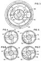
- Fign. 3 bis 6
- Querschnittsansichten durch den Mischer gemäß Fig. 2 entlang der dort angegebenen Linien III-III, IV-IV, V-V und VI-VI und
- Fig. 7
- eine Querschnittsansicht ähnlich der gemäß Fig. 6, jedoch bei einer alternativen Ausgestaltung der Mischerwelle.
- Fig. 1
- an overall side view of a discharge device for mixed pasty components,
- Fig. 2
- 2 shows a longitudinal section through the dynamic mixer as used in the discharge device according to FIG. 1,
- FIGS. 3 to 6
- Cross-sectional views through the mixer of FIG. 2 along lines III-III, IV-IV, VV and VI-VI and
- Fig. 7
- a cross-sectional view similar to that of FIG. 6, but with an alternative embodiment of the mixer shaft.
In Fig. 1 ist eine Austragvorrichtung 10 für zwei miteinander zu vermischende
pastöse Komponenten in Seitenansicht dargestellt. Die Vorrichtung 10 umfasst
einen Auspressteil 12 und einen Mischerteil 14, wobei der Auspressteil 12 zwei
Druckbehälter 16,18 zur Aufnahme zweier die pastösen Massen beinhaltenden
Schlauchbeutel 20,22 aufweist. An den vorderen stirnseitigen Enden 24,26 der
Druckbehälter 16,18 weisen diese Auslassstutzen 28,30 auf, über die bei
Ausübung eines Drucks auf das hintere Ende der Schlauchbeutel 20,22 deren
Inhalt ausgebracht wird. Die Druckbeaufschlagung der Schlauchbeutel 20,22
erfolgt mittels Druckstempeln 32,34, die motorisch angetrieben sind, was hier
nicht näher dargestellt ist.In Fig. 1 is a
Auf die Auslassstutzen 28,30 ist ein dynamischer Mischer 36 aufgesteckt, der
anhand der Fign. 2 bis 7 weiter unten genauer beschrieben werden wird. Ganz
allgemein lässt sich zu diesem dynamischen Mischer 36 sagen, dass seine
Mischerwelle 38 motorisch angetrieben ist. Zu diesem Zweck ist die
Mischerwelle 38 mit einer Antriebsstange 40 kuppelbar, die von einem ebenfalls
nicht dargestellten Motor drehend angetrieben wird.A
Die Einzelheiten des dynamischen Mischers 36 werden insbesondere anhand von
Fig. 2 deutlich. In dieser Figur ist ein Längsschnitt durch den Mischer 36
dargestellt. Der Mischer 36 weist ein Gehäuse 42 auf, das einen im wesentlichen
zylindrischen bzw. rohrförmigen Abschnitt 44 mit einem konisch aufgeweiteten
Endabschnitt 46 an dem dem Auspresswerkzeug 12 zugewandten hinteren Ende
48 und ein verjüngtes vorderes Ende 50 aufweist. Das verjüngte Ende 50 ist als
Auslassstutzen ausgebildet und definiert die Auslassöffnung 52 für das
Materialgemisch, während am hinteren Ende 48 des Gehäuses 42 zwei
Einlassstutzen 54,56 angeordnet sind, die auf die Auslassstutzen 28,30 des
Auspresswerkzeugs 12 aufsteckbar sind. Zwischen den beiden Einlassstutzen 54
befindet sich eine Durchbrechung 58, in der das eine Ende 60 der Mischerwelle
38 drehbar gelagert ist. Über diese Durchbrechung ist die Antriebsstange 40 mit
der Mischerwelle 38 kuppelbar.The details of the
Die Einlassstutzen 54,56 und die Durchbrechung 58 sind in einem Einsatzteil 62
ausgebildet, das am hinteren Ende 48 des Gehäuses 42 in dessen konischen
Aufweitungsabschnitt 46 eingesteckt ist. Ausgehend von den Einlassstutzen
54,56 erstrecken sich durch das Einsatzteil 62 zwei Kanäle 64,66, die unter
Umlenkung in radialen Öffnungen 68,70 münden. Diese Einlassöffnungen 68,70
sind bezogen auf den zylindrischen Abschnitt 44 des Mischergehäuses 42 radial
angeordnet. Über die Kanäle 64,66 werden die beiden pastösen Komponenten in
den dynamischen Mischer 36 hinein transportiert, wo sie dann in radialer
Richtung auf die Mischerwelle 38 auftreffen.The
Wie anhand von Fign. 2 und 3 zu erkennen ist, weist das Einsatzteil 62 eine
zentrale im wesentlichen zylindrische Aufnahmevertiefung 69 auf, die
konzentrisch zur Durchbrechung 58 angeordnet ist und in die die Mischerwelle
38 eingesetzt ist. In der zylindrischen Wandung 71 der Aufnahmevertiefung 69
sind die Einlassöffnungen 68,70 eingebracht. Ferner sind in diesem Bereich auch
die Kanäle 64,66 ausgebildet. Diese Kanäle 64,66 sind als oben offene Nuten
oder Aussparungen ausgebildet, die zusammen mit dem im wesentlichen konisch
aufgeweiteten Gehäuseabschnitt 46 die allseits geschlossenen Kanäle bilden.As shown in FIGS. 2 and 3 can be seen, the
Die Mischerwelle 38 weist eine drehbar gelagerte Achse 72 auf, von der in einer
Vielzahl von Radialebenen jeweils vier stegförmige Mischerelemente 74 im
wesentlichen radial abstehen. Die genaue Anordnung dieser Mischerelemente 74
ergibt sich aus der Schnittdarstellung gemäß Fig. 4. Zu erkennen ist, dass die
einen in Umfangsrichtung liegenden Begrenzungsseitenkanten der
Mischerelemente 74 im wesentlichen tangential zur Umfangsfläche der Achse 72
verlaufen. Wie sich aus Fig. 4 ergibt, sind also pro Radialebene vier
Mischerelemente 74 vorgesehen, die gemäß Fig. 2 bis nahe an die Innenfläche 76
des zylindrischen Gehäuseabschnitts 44 reichen. Der gesamte Bereich zwischen
den Einlassöffnungen 68,70 und dem Ende der Mischerwelle 38, die sich bis zum
sich verjüngenden Ende 50 des Mischergehäuses 42 erstreckt, ist mit diesen
Mischerelemente 74 versehen. Zusätzlich weist die Mischerwelle 38 nach Art
von Viertelkreisflächen ausgebildete Mischerelemente 78 auf, die durch
Verbinden jeweils zweier benachbarter Mischerelemente 74 eine Radialebene
gebildet sind (siehe beispielsweise die Schnittdarstellung gemäß Fig. 5). In dieser
Ausgestaltung ist die radial außenliegende Begrenzungskante des
Mischerelemente 78 kreisbogenförmig ausgebildet, während sie bei der
Alternativen gemäß Fig. 7 sekantiell verläuft. Das Mischerelement 78' gemäß
Fig. 7 weist also in einem mittleren Umfangsabschnitt einen größeren Abschnitt
zur Innenfläche 76 des zylindrischen Gehäuseabschnitts 44 auf. The
Während die Mischerelemente 74,78,78' aufgrund ihrer radialen Erstreckung bis
nahe an den zylindrischen Gehäuseabschnitt 44 bei Rotation der Mischerwelle 38
für eine Umlenkung und damit Verwirbelung der an sich axial strömenden
pastösen Massen sorgen, weist die Mischerwelle 38 im Bereich der radialen
Einlassöffnungen 68,70 zwei Umlenkelemente 80 auf, die nach Art einer
Förderschnecke ausgebildet sind. Die Umlenkelemente 80 sind als
sägezahnförmige Keile ausgebildet, die sich über etwa 90° um die Achse 72 der
Mischerwelle 38 herum erstrecken. Die Umlenkelemente 80 weisen eine in
Umfangsrichtung ansteigende Umlenkfläche 82 auf, die in Richtung zum
Auslassende 52 des dynamischen Mischers 36 weist und winklig zu einer radial
zur Achse 72 verlaufenden Ebene verlaufen. Diese Umlenkelemente 80 verlaufen
also abschnittsweise schraubenlinienförmig und sorgen für eine axiale
Bewegungskomponente der pastösen Massenströme. Damit unterstützen die
Umlenkelemente 80 den Abtransport von pastöser Masse, die aus den
Einlassöffnungen 68,70 in den zylindrischen Gehäuseabschnitt 44 eindringt.
Dieses unterstützende und damit verstärkende Abführen der pastösen Massen in
axialer Richtung verringert die Gefahr der Kontamination der beiden pastösen
Massen, d.h. die ungewollte Vermischung bzw. Rückkontamination der beiden
pastösen Massen über die Einlassöffnungen 68,70 in die Kanäle 64,66 hinein und
gegebenenfalls weiter bis in die Auslassstutzen 28,30. Denn wenn es in diesen
Bereichen zu einer Kontamination und damit zu einer Polymerisation kommt,
lässt sich aufgrund der Verstopfung der Auslassstutzen 28,30 das gegebenenfalls
noch in den Schlauchbeuteln 20,22 befindliche Restmaterial nicht mehr
austragen.While the
Anhand von Fig. 6 soll noch auf ein weiteres Merkmal des dynamischen
Mischers 36 eingegangen werden. Bei den zuvor erwähnten Mischerelementen
74 handelt es sich um starre im wesentlichen radial abstehende Stege, die
aufgrund der Rotation der Achse 72 zu einer Verwirbelung der Massenströme
führen. Zusätzlich zu den starren Mischerelementen 74 weist der dynamische
Mischer 36 nach Art von dünnen flexiblen Stegen ausgebildete weitere
Mischerelemente 84 auf, die von innen an der Innenseite 76 des zylindrischen
Gehäuseabschnitts 44 entlangstreichen. Auch diese zusätzlichen flexiblen
Mischerelemente 84 sorgen für eine Verwirbelung der Massenströme. Von den
flexiblen Mischerelementen 84 existieren in mehreren aufeinanderfolgenden
Radialebenen der Mischerwelle 38 jeweils eines pro Ebene, wobei diese
Mischerelemente 84 um einen konstanten Winkelbereich von Radialebene zu
Radialebene versetzt angeordnet sind. Selbiges gilt für die Mischerelemente 78
bzw. 78', die jeweils zwei benachbarte Mischerelemente 74 miteinander
verbinden und ebenfalls um in diesem Fall 90° versetzt von Radialebene zu
Radialebene angeordnet sind. Die Mischerelemente 84 und die Mischerelemente
78 bzw. 78' sind also längs einer Schraubenlinie um die Achse 72 herum
gleichmäßig verteilt angeordnet. Beide Mischerelementtypen eigenen sich
vorzüglich für eine homogene Durchmischung der pastösen Massen in dem auch
als Durchlaufmischer zu bezeichnenden dynamischen Mischer 36.With reference to FIG. 6, yet another characteristic of the
Claims (8)
- A device for mixing two pasty substances, particularly for mixing a dental impression substance with a catalyst substance, comprisingcharacterized ina housing (42) comprising a substantially tubular portion (44) with two inlet openings (68,70) for the two pasty substances at the rear end of the housing (42), and with an outlet opening (52) for the mixed pasty substances at the front end of the tubular portion (44),a drivable mixer shaft (38) extending through the tubular portion (44) and supported for rotation in the housing (42),the mixer shaft (38) comprising a plurality of rigid mixing elements (74) projecting from an axis (72), for mixing the two pasty substances when these pass through the tubular portion (44) of the housing (42), andan insert member (62) arranged on the rear end (48) of the housing (42) and extending transverse to the axis (72), the insert member (62) comprising an inner side facing towards the tubular portion (44) of the housing (42), and an outer side forming the rear end (48) of the housing (42) and provided with two inlet connectors,that the inlet connectors (54,56) on the outer side of the insert member (62) have two channels (64,66) extending therefrom which are arranged to enter into radial openings, forming the inlet openings (68,70), of the cylindrical receiving recess (69) on the inner side of the insert members (62).that the inlet openings (68,70) are arranged to enter radially into the substantially tubular portion (44) of the housing (42),that the mixer shaft (38) at the level of the radial inlet openings (68,70) comprises at least one deflection element (80) for deflecting into the axial direction the pasty substances radially entering the tubular portion (44) of the housing (42) through the inlet openings (68,70), wherein the at least one deflection element (80) comprises a deflection face (82) extending around the axis (72) and oriented obliquely relative to a radial plane of the axis (72),that the insert member (62) has its inner side formed with a cylindrical receiving recess (69) for the portion of the mixer shaft (38) carrying the at least one deflection element (80), and
- The device according to claim 1, characterized in that the at least one deflection element (80) is wedge-shaped.
- The device according to claim 1 or 2, characterized in that two deflection elements (80) are provided which are arranged diametrically opposite each other around the axis (72).
- The device according to any one of claims 1 to 3, characterized in that the two deflection elements (80) extend respectively around an angular region of 90° to 180°.
- The device according to any one of claims 1 to 4, characterized in that the at least one deflection element (80) comprises a deflection face (82) extending helically around the axis (72).
- The device according to any one of claims 1 to 5, characterized in that, within a plurality of radial planes, respectively identical numbers of mixing elements (74) extend from the axis (72) up to the close vicinity of the inner face (76) of the tubular portion (44) of the housing (42).
- The device according to claim 6, characterized in that, within a plurality of radial planes being equal in number to the mixing elements (74) per radial plane, respectively two circumferentially adjacent mixing elements (74) are connected to each other by a partial portion (78,78') extending in the circumferential direction, and that these pairs of mutually connected mixing elements (74) are displaced in the circumferential direction from each radial plane to the next radial plane.
- The device according to any one of claims 1 to 7, characterized in that the mixer shaft (38) comprises a plurality of radially projecting stripper elements (84) which are flexible and have free ends arranged to sweep along the inner side (76) of the tubular portion (44) of the housing (42) and facing away from the axis (72).
Applications Claiming Priority (3)
| Application Number | Priority Date | Filing Date | Title |
|---|---|---|---|
| DE29818280 | 1998-10-14 | ||
| DE29818280U | 1998-10-14 | ||
| PCT/EP1999/007703 WO2000021652A1 (en) | 1998-10-14 | 1999-10-14 | Device for mixing two pasty materials, especially for mixing a dental impression material with a catalyst material |
Publications (2)
| Publication Number | Publication Date |
|---|---|
| EP1121194A1 EP1121194A1 (en) | 2001-08-08 |
| EP1121194B1 true EP1121194B1 (en) | 2003-01-02 |
Family
ID=8063860
Family Applications (5)
| Application Number | Title | Priority Date | Filing Date |
|---|---|---|---|
| EP99953812A Expired - Lifetime EP1121194B1 (en) | 1998-10-14 | 1999-10-14 | Device for mixing two pasty materials, especially for mixing a dental impression material with a catalyst material |
| EP01108465A Expired - Lifetime EP1112779B1 (en) | 1998-10-14 | 1999-10-14 | Opener for opening two tubular bags each comprising a paste |
| EP01108464A Expired - Lifetime EP1138397B1 (en) | 1998-10-14 | 1999-10-14 | Opener for opening a tubular bag comprising a pasty material |
| EP01108463A Expired - Lifetime EP1138396B1 (en) | 1998-10-14 | 1999-10-14 | Opener for opening a tubular bag comprising a pasty material |
| EP99953813A Revoked EP1121195B1 (en) | 1998-10-14 | 1999-10-14 | Device for applying a pasty two-component mixture |
Family Applications After (4)
| Application Number | Title | Priority Date | Filing Date |
|---|---|---|---|
| EP01108465A Expired - Lifetime EP1112779B1 (en) | 1998-10-14 | 1999-10-14 | Opener for opening two tubular bags each comprising a paste |
| EP01108464A Expired - Lifetime EP1138397B1 (en) | 1998-10-14 | 1999-10-14 | Opener for opening a tubular bag comprising a pasty material |
| EP01108463A Expired - Lifetime EP1138396B1 (en) | 1998-10-14 | 1999-10-14 | Opener for opening a tubular bag comprising a pasty material |
| EP99953813A Revoked EP1121195B1 (en) | 1998-10-14 | 1999-10-14 | Device for applying a pasty two-component mixture |
Country Status (6)
| Country | Link |
|---|---|
| US (2) | US6394643B1 (en) |
| EP (5) | EP1121194B1 (en) |
| AT (5) | ATE236716T1 (en) |
| DE (6) | DE59904990D1 (en) |
| ES (4) | ES2190263T3 (en) |
| WO (2) | WO2000021652A1 (en) |
Families Citing this family (91)
| Publication number | Priority date | Publication date | Assignee | Title |
|---|---|---|---|---|
| EP1072323B1 (en) | 1999-07-29 | 2003-09-10 | Wilhelm A. Keller | Cartridge discharge device with actuator for dynamic mixers |
| DE19947331C2 (en) * | 1999-10-01 | 2002-02-28 | 3M Espe Ag | Dynamic mixer |
| WO2001032242A1 (en) * | 1999-11-03 | 2001-05-10 | Dentaco Dentalindustrie Und -Marketing Gmbh | Multi-chambered ampoule for dispensing a mixture comprising several substances |
| ATE273065T1 (en) * | 1999-11-12 | 2004-08-15 | Kettenbach Gmbh & Co Kg | DEVICE FOR MIXING TWO PASTY MASSES, IN PARTICULAR FOR MIXING A DENTAL IMPRESSION MATERIAL WITH A CATALYST MATERIAL |
| US6443612B1 (en) * | 1999-12-02 | 2002-09-03 | Wilhelm A. Keller | Dynamic mixer |
| EP1110599B1 (en) * | 1999-12-23 | 2003-04-09 | Ernst Mühlbauer GmbH & Co.KG | Dynamic mixer for dental impression pastes |
| US8093823B1 (en) | 2000-02-11 | 2012-01-10 | Altair Engineering, Inc. | Light sources incorporating light emitting diodes |
| DE10019893C2 (en) * | 2000-04-20 | 2003-05-28 | 3M Espe Ag | Device in the form of a dynamic mixer or a cartridge front and their use |
| US6609612B2 (en) * | 2000-11-01 | 2003-08-26 | James A. Vlodek | Closure with selectively operable dispense feature |
| US6959841B2 (en) * | 2000-11-01 | 2005-11-01 | Vlodek James A | Closure with selectively operable dispense feature |
| DE10112904C5 (en) | 2001-03-15 | 2010-04-22 | 3M Espe Ag | Dynamic mixer and method for mixing at least two paste components |
| DE10164385C1 (en) * | 2001-12-28 | 2003-03-06 | Kettenbach Gmbh & Co Kg | Device for mixing two paste-like substances for dental work includes first channel extending through coupling section and having first and second parts with adjoining deflection section inbetween to ensure constant mixing ratio at outlet |
| GB0206343D0 (en) * | 2002-03-18 | 2002-05-01 | Cussons Int Ltd | Fluid dispenser |
| US20040033466A1 (en) * | 2002-08-15 | 2004-02-19 | Kerr Corporation | Single dose dental restorative material delivery system and method |
| DE10254409A1 (en) * | 2002-11-21 | 2004-06-03 | Ernst Mühlbauer Gmbh & Co. Kg | Device for mixing and dispensing multicomponent masses |
| US6843652B2 (en) * | 2002-12-06 | 2005-01-18 | Kerr Corporation | Single dose dental impression material delivery system and method |
| DE10258953A1 (en) * | 2002-12-16 | 2004-07-22 | S&C Polymer Silicon- und Composite-Spezialitäten GmbH | Dispenser for fluid substances |
| CA2517014C (en) * | 2003-03-06 | 2012-07-17 | Dentsply International Inc. | Dispensing and mixing tip |
| CA2535630C (en) * | 2003-08-14 | 2012-04-10 | 3M Innovative Properties Company | Capsule for two-component materials |
| DE60300822T2 (en) | 2003-08-14 | 2006-04-13 | 3M Espe Ag | Mixing element for a multi-component paste mixer, and mixer with this mixing element |
| JP4413561B2 (en) * | 2003-09-01 | 2010-02-10 | 株式会社ジーシー | Dental impression mixing mixer |
| DE10360366A1 (en) * | 2003-12-22 | 2005-07-21 | Agfaphoto Gmbh | Containers for photographic processing chemicals |
| DE102004002654A1 (en) * | 2004-01-16 | 2005-08-18 | Heraeus Kulzer Gmbh | Device for level control of multi-component materials |
| DE102004003774A1 (en) * | 2004-01-23 | 2005-08-25 | Heraeus Kulzer Gmbh | Device for opening a tubular bag and its use |
| JP4485227B2 (en) * | 2004-03-12 | 2010-06-16 | 株式会社ジーシー | Dental impression material kneading device |
| EP1588779A1 (en) * | 2004-04-19 | 2005-10-26 | 3M Espe AG | Dynamic mixer |
| DE102004030407A1 (en) * | 2004-06-23 | 2006-01-19 | Heraeus Kulzer Gmbh | Cartridge for pasty materials |
| WO2006005213A1 (en) * | 2004-07-08 | 2006-01-19 | Mixpac Systems Ag | Disposable discharge device |
| ATE462459T1 (en) * | 2004-07-16 | 2010-04-15 | Dentaco Gmbh | MULTI-CHAMBER AMPOULE FOR DISPENSING A MIXTURE CONSISTING OF SEVERAL SUBSTANCES |
| US8322909B2 (en) * | 2004-09-22 | 2012-12-04 | 3M Deutschland Gmbh | Mixer for multi-component pastes, kit, and method of mixing paste components |
| EP1640060A1 (en) | 2004-09-22 | 2006-03-29 | 3M Espe Ag | Mixer for multi-component pastes, kit, and method of mixing paste components |
| US20120017412A1 (en) * | 2004-12-03 | 2012-01-26 | Paul Richard Pierson | Package and dispensing system |
| DE102005061921B4 (en) * | 2005-01-20 | 2010-04-08 | Kettenbach Gmbh & Co. Kg | Device for storing and discharging fluid substances |
| DE202005000929U1 (en) * | 2005-01-20 | 2005-03-31 | Kettenbach Gmbh & Co Kg | Device for storing and discharging fluid substances |
| DE202005005833U1 (en) * | 2005-02-25 | 2005-06-23 | Vosschemie Gmbh | Dispenser and mixer for two component reactive resin-fillers e.g. for repair of automobile bodywork |
| EP1724208B1 (en) * | 2005-05-18 | 2010-03-31 | Dentaco Dentalindustrie- und Marketing GmbH | Multi-chamber dispenser |
| WO2007041878A1 (en) * | 2005-10-07 | 2007-04-19 | Sulzer Mixpac Ag | Dynamic mixer |
| US8197545B2 (en) * | 2005-10-27 | 2012-06-12 | Depuy Spine, Inc. | Nucleus augmentation delivery device and technique |
| US7918336B2 (en) * | 2005-11-02 | 2011-04-05 | Tastein Technology As | Closure device with corrugated ring plunger part |
| JP2009527420A (en) | 2006-02-21 | 2009-07-30 | メッドミックス システムズ アーゲー | Apparatus for punching film bags |
| WO2007098624A1 (en) * | 2006-03-01 | 2007-09-07 | Medmix Systems Ag | Two-part double syringe |
| CN101400315B (en) * | 2006-03-09 | 2013-03-27 | 3M创新有限公司 | Device for dispensing material |
| WO2008063222A2 (en) * | 2006-05-11 | 2008-05-29 | Dentsply International Inc. | Aerosol delivery system for dispensing dental compositions |
| DE102006022880B4 (en) | 2006-05-15 | 2010-09-30 | Kettenbach Gmbh & Co. Kg | Multi-stage process for the sterilization of hardenable, medical multi-component impression materials |
| DE102006038897B4 (en) * | 2006-08-18 | 2014-10-16 | Mühlbauer Technology Gmbh | Apparatus for generating a multicomponent mass |
| EP2486910A3 (en) * | 2006-10-27 | 2012-08-22 | The Curators Of The University Of Missouri | Multi-chambered apparatus comprising a dispenser head |
| AU2007333884B2 (en) | 2006-12-15 | 2012-02-16 | 3M Innovative Properties Company | Mixing and dispensing curable multi-component materials |
| DE102007000066A1 (en) * | 2007-02-01 | 2008-09-18 | Hilti Aktiengesellschaft | Container with a bag pack and a headboard |
| DE102007015842A1 (en) | 2007-03-30 | 2008-10-02 | Heraeus Kulzer Gmbh | Machinable A-Silicon Putty and its use |
| DE102007018143B3 (en) * | 2007-04-16 | 2008-06-05 | Kettenbach Gmbh & Co. Kg | Container e.g. tubular bag, for receiving e.g. liquid substance, has nozzle and sleeve with lengths adjusted such that sleeve is movable from storage position, in which sleeve does not project, into activation position, by inserting pieces |
| DE102008005743A1 (en) | 2008-01-23 | 2009-08-06 | Heraeus Kulzer Gmbh | Device for storing fluid components for the dental sector |
| CH699115A1 (en) * | 2008-07-14 | 2010-01-15 | Medmix Systems Ag | A dispensing assembly with a cartridge bag. |
| DE102008040738A1 (en) * | 2008-07-25 | 2010-01-28 | Hilti Aktiengesellschaft | foilpack |
| CH699391A1 (en) | 2008-08-19 | 2010-02-26 | Medmix Systems Ag | A dispensing assembly with a cartridge bag. |
| DE202008012785U1 (en) | 2008-09-25 | 2008-12-11 | Heraeus Kulzer Gmbh | Machinable A-Silicon Putty and its use |
| CA2740768C (en) * | 2008-10-17 | 2016-04-05 | Olympus Medical Systems Corp. | Fluid container unit and method for injecting different kinds of fluids into fluid usage equipment |
| JP2010264994A (en) * | 2009-05-13 | 2010-11-25 | Asahi Kasei Chemicals Corp | Cartridge system for pouring material |
| US8424713B2 (en) * | 2009-12-17 | 2013-04-23 | Michael J. Bolland | Multiple container retaining device and method for using same |
| USD657876S1 (en) | 2010-02-02 | 2012-04-17 | 3M Innovative Properties Company | Dental capsule |
| TWI468194B (en) * | 2010-03-22 | 2015-01-11 | Phillip Phung-I Ho | A variety of material mixing devices |
| AT509898B1 (en) * | 2010-05-27 | 2012-09-15 | Rainer Weber | MULTI-CHAMBER CONTAINERS WITH AT LEAST TWO CONTAINERS FILLED WITH Pourable Content |
| EP2399666B1 (en) * | 2010-06-22 | 2013-02-20 | 3M Innovative Properties Company | Mixer for preparing a dental material, and system comprising the same |
| DE102010046056B3 (en) | 2010-09-22 | 2012-03-15 | Heraeus Medical Gmbh | Cartridge system with device for synchronizing two fluid streams |
| EP2468415A1 (en) * | 2010-12-24 | 2012-06-27 | Sika Technology AG | Dosing and mixing apparatus for multi-pack products |
| EP2468416A1 (en) | 2010-12-24 | 2012-06-27 | Sika Technology AG | Application device for multi-pack products, cartridge set and packaging unit |
| KR101913678B1 (en) * | 2011-02-28 | 2018-10-31 | 술저 믹스팩 아게 | Dynamic mixer and use thereof |
| DK2520360T3 (en) * | 2011-05-02 | 2014-09-01 | Sulzer Mixpac Ag | MIXING MACHINE FOR MIXING AT LEAST TWO VOLUMEABLE COMPONENTS AND DRAWING DEVICE |
| KR101477332B1 (en) * | 2011-08-10 | 2014-12-29 | 필립 풍-아이 호 | Device for mixing and discharging plural materials |
| US20130277391A1 (en) * | 2011-09-27 | 2013-10-24 | Adco Products, Inc. | Adhesive package |
| CN103998149B (en) * | 2011-10-17 | 2017-03-29 | 苏舍米克斯帕克有限公司 | Cylinder and multicomponent cartridge |
| USD716143S1 (en) | 2011-11-22 | 2014-10-28 | 3M Innovative Properties Company | End cap for a container |
| EP2606987A1 (en) * | 2011-12-21 | 2013-06-26 | Sika Technology AG | Application system, battery powered application device and process for bonding |
| DE102012218551B3 (en) * | 2012-10-11 | 2014-02-13 | Hilti Aktiengesellschaft | Method for producing a film package for a dispensing device with prefilled head part |
| US9579686B2 (en) * | 2012-10-29 | 2017-02-28 | Nordson Corporation | Fluid dispensing assemblies and methods of dispensing fluids from containers |
| KR102023143B1 (en) * | 2012-11-08 | 2019-09-19 | 술저 믹스팩 아게 | Cartridge for at least two flowable components |
| KR101406068B1 (en) * | 2013-09-05 | 2014-06-11 | (주)디엑스엠 | Impression mixing tip |
| DE202013009790U1 (en) * | 2013-12-04 | 2015-03-05 | Mühlbauer Technology Gmbh | Dynamic mixer |
| CN103708125A (en) * | 2013-12-05 | 2014-04-09 | 张家港市龙冠特种装饰材料厂 | Storage container for dual-component glue |
| EP2959861A1 (en) * | 2014-06-23 | 2015-12-30 | Sulzer Mixpac AG | Syringe for multi-component materials |
| EP2965825A1 (en) * | 2014-07-09 | 2016-01-13 | Sulzer Mixpac AG | Dispensing apparatus, dispensing system and method of dispensing |
| CN107920882B (en) * | 2015-08-19 | 2020-12-08 | 高露洁-棕榄公司 | Multi-chemical dispenser |
| EP3195941A1 (en) * | 2016-01-20 | 2017-07-26 | HILTI Aktiengesellschaft | Press-out device for a film package, film package and assembly comprising a press- out device and a film package |
| CN107335590B (en) * | 2017-02-03 | 2023-12-15 | 固安县朝阳生物科技有限公司 | Porcelain tooth hides look coating unit |
| DE102018119838A1 (en) * | 2018-08-15 | 2020-02-20 | Atlas Copco Ias Gmbh | Device for applying an at least two-component viscous material to workpieces |
| EP3632575A1 (en) * | 2018-10-02 | 2020-04-08 | Sulzer Mixpac AG | Reusable cartridge piston |
| EP3834951A1 (en) * | 2019-12-13 | 2021-06-16 | Hilti Aktiengesellschaft | Cartridge for a pressing device |
| WO2021165785A1 (en) * | 2020-02-19 | 2021-08-26 | 3M Innovative Properties Company | Dispensing device for a dental substance |
| DE102020134316A1 (en) * | 2020-12-18 | 2022-06-23 | Kulzer Gmbh | Rotor shaft with worm thread for a dynamic mixer for mixing low to high viscosity components |
| GB2608361A (en) * | 2021-06-23 | 2023-01-04 | Tristel Plc | Method and apparatus for preparing a liquid preparation |
| DE102022210641A1 (en) | 2022-10-07 | 2024-04-18 | GalvoSurge Dental AG | Application nozzle for applying a dental active substance in the oral cavity of a patient and active substance applicator with such an application nozzle |
| DE102022119523A1 (en) | 2022-08-03 | 2024-02-08 | GalvoSurge Dental AG | Application nozzle for applying a dental active ingredient in the oral cavity of a patient and active ingredient applicator with such an application nozzle |
Family Cites Families (42)
| Publication number | Priority date | Publication date | Assignee | Title |
|---|---|---|---|---|
| US3051455A (en) * | 1960-07-25 | 1962-08-28 | Gen Electric | Mixing nozzle |
| BE625883A (en) * | 1961-12-08 | |||
| DE1486405A1 (en) * | 1965-04-15 | 1969-06-04 | H V Hardman Company Inc | Device for mixing and dispensing materials |
| US3390814A (en) * | 1965-09-24 | 1968-07-02 | Chem Dev Corp | Mixing device |
| US3570719A (en) * | 1968-07-02 | 1971-03-16 | Louis Schiff | Reagent mixing and dispensing apparatus |
| US3587982A (en) * | 1969-01-15 | 1971-06-28 | Ncr Co | Adhesive and sealant dispenser with grinding means |
| US3711067A (en) * | 1971-01-08 | 1973-01-16 | Midland Ross Corp | Extruding and mixing equipment |
| US3767085A (en) * | 1971-08-02 | 1973-10-23 | J Cannon | Mixing syringe |
| US4107793A (en) * | 1977-05-26 | 1978-08-15 | Monsanto Company | Mixer apparatus for continuously coagulating an aqueous latex and consolidating as a paste coagulum |
| DE2949369A1 (en) * | 1979-12-07 | 1981-06-11 | Hilti AG, 9494 Schaan | DEVICE FOR DELIVERING MULTI-COMPONENT DIMENSIONS |
| EP0039245A1 (en) * | 1980-04-30 | 1981-11-04 | Black & Decker | Cartridge assembly |
| DE3128611C2 (en) * | 1981-07-20 | 1994-07-14 | Hilti Ag | Dosing device for multi-component masses |
| JPS59500122A (en) * | 1982-02-05 | 1984-01-26 | シユナイダ−,ハンス クラウス | Equipment for mixing dental materials |
| CH669575A5 (en) * | 1985-08-20 | 1989-03-31 | Alfatechnic Ag | |
| DE3542522C2 (en) * | 1985-12-02 | 1993-10-28 | Hilti Ag | Handheld device for mixing and dispensing two-component masses |
| FR2622546B2 (en) * | 1987-05-25 | 1990-03-16 | Emballages Conseils Etudes | CLOSING DEVICE FOR CONTAINERS |
| DE3723517A1 (en) * | 1987-07-16 | 1989-01-26 | Licentia Gmbh | HAND-DRIVEN, MOTOR-DRIVEN ELECTRIC TOOL |
| BE1000760A6 (en) * | 1987-07-27 | 1989-03-28 | Lynes Holding Sa | POURING CAP DEVICE. |
| DE3823708C2 (en) * | 1988-07-13 | 1994-04-14 | Atlas Copco Elektrowerkzeuge | Motor-driven device for dosing and mixing at least two substances |
| CH674717A5 (en) * | 1987-11-10 | 1990-07-13 | Profil Ag | Mixing device for at least two cartridges - has mixing head, semi-outer welded shells, supplies, strips or screw conveyor |
| EP0319639A1 (en) * | 1987-12-07 | 1989-06-14 | Lawrence Dr. Colin | Dispensing mixer for the storage and mixing of separate materials |
| US4951843A (en) * | 1989-08-16 | 1990-08-28 | Sealant Equipment & Engineering, Inc. | Disposable mixing chamber liner and paddle for a dynamic mixing and dispensing gun |
| DE9017323U1 (en) * | 1990-12-21 | 1992-04-16 | Thera Patent Gmbh & Co Kg Gesellschaft Fuer Industrielle Schutzrechte, 8031 Seefeld, De | |
| US5161715A (en) * | 1991-03-25 | 1992-11-10 | Giannuzzi Anthony C | Double-barreled epoxy injection gun |
| DE4235736C1 (en) * | 1992-10-23 | 1994-03-24 | Bergmann Franz Josef | Device for mixing and distributing paste pulp - comprises combination of static mixer with channels for the breakdown and pre-distribution of the pulp into a number of thin strands |
| JPH06226178A (en) * | 1993-04-06 | 1994-08-16 | Kenwood Corp | Bonding agent dispenser |
| GB9403362D0 (en) * | 1994-02-22 | 1994-04-13 | Summit Medical Ltd | Bone cement mixing apparatus |
| JPH08187727A (en) * | 1995-01-11 | 1996-07-23 | Teijin Ltd | Thermosetting resin mixer |
| DE19500782A1 (en) * | 1995-01-13 | 1996-07-18 | Bayer Ag | Device for mixing and applying a molding compound |
| US5609271A (en) * | 1995-01-25 | 1997-03-11 | Wilhelm A. Keller | Mixer and multiple component dispensing device assembly and method for the aligned connection of the mixer to the multiple component dispensing device |
| ES2164750T3 (en) | 1995-03-07 | 2002-03-01 | Wilhelm A Keller | BAYONETA FIXING DEVICE FOR HOLDING AN ACCESSORY TO A CARTRIDGE OF MULTIPLE COMPONENTS OR DISTRIBUTING DEVICE. |
| DE59710147D1 (en) | 1996-02-05 | 2003-07-03 | 3M Espe Ag | Device for emptying a tubular bag |
| DE19710878C1 (en) * | 1997-03-15 | 1998-07-02 | Henkel Kgaa | Cartridge system with applicator gun |
| DE29705741U1 (en) * | 1997-04-01 | 1998-08-06 | Muehlbauer Ernst Kg | Dynamic mixer for dental impression materials |
| DE29818499U1 (en) * | 1998-10-16 | 2000-03-02 | Espe Dental Ag | Mixer for multi-component pastes |
| DE29819661U1 (en) * | 1998-11-04 | 1999-02-25 | Kress Elektrik Gmbh & Co | Device for squeezing and dispensing flowable multi-components |
| EP1072323B1 (en) * | 1999-07-29 | 2003-09-10 | Wilhelm A. Keller | Cartridge discharge device with actuator for dynamic mixers |
| DE19947331C2 (en) * | 1999-10-01 | 2002-02-28 | 3M Espe Ag | Dynamic mixer |
| US6443612B1 (en) * | 1999-12-02 | 2002-09-03 | Wilhelm A. Keller | Dynamic mixer |
| EP1110599B1 (en) * | 1999-12-23 | 2003-04-09 | Ernst Mühlbauer GmbH & Co.KG | Dynamic mixer for dental impression pastes |
| DE10015133C1 (en) * | 2000-03-29 | 2001-09-27 | Heraeus Kulzer Gmbh & Co Kg | Dynamic mixer for dental materials has at least two paddles in succession at the mixer on the side towards the chamber closure which do not strip the chamber walls |
| DE50103064D1 (en) * | 2000-03-29 | 2004-09-09 | Heraeus Kulzer Gmbh & Co Kg | Dynamic mixer |
-
1999
- 1999-10-14 EP EP99953812A patent/EP1121194B1/en not_active Expired - Lifetime
- 1999-10-14 ES ES99953812T patent/ES2190263T3/en not_active Expired - Lifetime
- 1999-10-14 DE DE59904990T patent/DE59904990D1/en not_active Revoked
- 1999-10-14 ES ES01108463T patent/ES2254279T3/en not_active Expired - Lifetime
- 1999-10-14 US US09/807,503 patent/US6394643B1/en not_active Expired - Lifetime
- 1999-10-14 DE DE59903929T patent/DE59903929D1/en not_active Expired - Lifetime
- 1999-10-14 EP EP01108465A patent/EP1112779B1/en not_active Expired - Lifetime
- 1999-10-14 AT AT99953813T patent/ATE236716T1/en not_active IP Right Cessation
- 1999-10-14 AT AT01108463T patent/ATE314155T1/en not_active IP Right Cessation
- 1999-10-14 AT AT01108464T patent/ATE285850T1/en not_active IP Right Cessation
- 1999-10-14 DE DE59908763T patent/DE59908763D1/en not_active Expired - Lifetime
- 1999-10-14 DE DE29923938U patent/DE29923938U1/en not_active Expired - Lifetime
- 1999-10-14 ES ES99953813T patent/ES2194521T3/en not_active Expired - Lifetime
- 1999-10-14 EP EP01108464A patent/EP1138397B1/en not_active Expired - Lifetime
- 1999-10-14 AT AT01108465T patent/ATE260713T1/en not_active IP Right Cessation
- 1999-10-14 DE DE59912995T patent/DE59912995D1/en not_active Expired - Lifetime
- 1999-10-14 AT AT99953812T patent/ATE230299T1/en not_active IP Right Cessation
- 1999-10-14 WO PCT/EP1999/007703 patent/WO2000021652A1/en active IP Right Grant
- 1999-10-14 ES ES01108465T patent/ES2217049T3/en not_active Expired - Lifetime
- 1999-10-14 DE DE59911383T patent/DE59911383D1/en not_active Expired - Lifetime
- 1999-10-14 US US09/807,516 patent/US6352177B1/en not_active Expired - Fee Related
- 1999-10-14 EP EP01108463A patent/EP1138396B1/en not_active Expired - Lifetime
- 1999-10-14 WO PCT/EP1999/007704 patent/WO2000021653A1/en not_active Application Discontinuation
- 1999-10-14 EP EP99953813A patent/EP1121195B1/en not_active Revoked
Also Published As
| Publication number | Publication date |
|---|---|
| EP1112779A2 (en) | 2001-07-04 |
| EP1112779B1 (en) | 2004-03-03 |
| EP1138397A3 (en) | 2001-11-28 |
| EP1138396A3 (en) | 2001-11-28 |
| EP1138396B1 (en) | 2005-12-28 |
| EP1112779A3 (en) | 2001-07-11 |
| EP1138397B1 (en) | 2004-12-29 |
| ES2254279T3 (en) | 2006-06-16 |
| EP1121195B1 (en) | 2003-04-09 |
| WO2000021653A1 (en) | 2000-04-20 |
| US6394643B1 (en) | 2002-05-28 |
| ATE260713T1 (en) | 2004-03-15 |
| EP1138397A2 (en) | 2001-10-04 |
| ATE230299T1 (en) | 2003-01-15 |
| DE59903929D1 (en) | 2003-02-06 |
| US6352177B1 (en) | 2002-03-05 |
| DE29923938U1 (en) | 2001-07-19 |
| EP1121195A1 (en) | 2001-08-08 |
| ES2190263T3 (en) | 2003-07-16 |
| DE59911383D1 (en) | 2005-02-03 |
| DE59912995D1 (en) | 2006-02-02 |
| ES2217049T3 (en) | 2004-11-01 |
| EP1138396A2 (en) | 2001-10-04 |
| ES2194521T3 (en) | 2003-11-16 |
| ATE285850T1 (en) | 2005-01-15 |
| WO2000021652A1 (en) | 2000-04-20 |
| ATE236716T1 (en) | 2003-04-15 |
| DE59908763D1 (en) | 2004-04-08 |
| ATE314155T1 (en) | 2006-01-15 |
| DE59904990D1 (en) | 2003-05-15 |
| EP1121194A1 (en) | 2001-08-08 |
Similar Documents
| Publication | Publication Date | Title |
|---|---|---|
| EP1121194B1 (en) | Device for mixing two pasty materials, especially for mixing a dental impression material with a catalyst material | |
| EP1099470B1 (en) | Device for mixing two pasty materials, especially for mixing a dental impression material with a catalyst material | |
| EP1458467B1 (en) | Device for mixing two pasty materials, in particular for mixing a dental impression material with a catalyst material | |
| EP0971787B1 (en) | Dynamic mixer for dental impression pastes | |
| DE102006049171B4 (en) | Device for continuous and intensive mixing of dry mortar | |
| DE10112904C5 (en) | Dynamic mixer and method for mixing at least two paste components | |
| EP1110599B1 (en) | Dynamic mixer for dental impression pastes | |
| EP2520360B1 (en) | Mixer for mixing at least two flowable components, and application device | |
| EP2384822B1 (en) | Cartridge lock and cartridge with such a lock | |
| EP1218094B1 (en) | Dynamic mixer | |
| EP1149627B1 (en) | Dynamic mixer | |
| EP1637282A1 (en) | Dry ice blasting device | |
| DE3809661A1 (en) | Apparatus for continuously mixing a building material | |
| DE2105020A1 (en) | Mixing device | |
| EP1688176B1 (en) | Pumping and mixing apparatus for powder and liquid materials and sytem for producing viscous materials for building purposes | |
| DE60002980T2 (en) | MULTI-WAVE SCREW EXTRUDER SOCKET AND EXTRUDER | |
| EP1900443B1 (en) | Device for mixing a binder and a hardener component for producing a ready-to-use body filler | |
| DE10043489A1 (en) | Dynamic mixer used for mixing viscous multiple component materials, especially dental material has a mixing element with mixing wings arranged on the side facing the closing part | |
| EP1595594A1 (en) | Dynamic mixer | |
| DE2219352A1 (en) | Continuous horizontal fixed drum mixer - for chips, fibres or powder, with liq | |
| DE19514384C2 (en) | Mixing or dispersing device with a guide housing | |
| EP1825924A1 (en) | Apparatus and method for mixing a binder and a curing agent to produce a ready for use filler mass. | |
| EP0620039A1 (en) | Homogenising device or similar | |
| WO1994005412A1 (en) | Device for mixing substances | |
| DE2742018A1 (en) | Two component plastics foam mixing head - has conical insert in chamber with component mixing cylinder in injection nozzle of spray gun |
Legal Events
| Date | Code | Title | Description |
|---|---|---|---|
| PUAI | Public reference made under article 153(3) epc to a published international application that has entered the european phase |
Free format text: ORIGINAL CODE: 0009012 |
|
| 17P | Request for examination filed |
Effective date: 20010331 |
|
| AK | Designated contracting states |
Kind code of ref document: A1 Designated state(s): AT BE CH CY DE DK ES FI FR GB GR IE IT LI LU MC NL PT SE |
|
| GRAG | Despatch of communication of intention to grant |
Free format text: ORIGINAL CODE: EPIDOS AGRA |
|
| 17Q | First examination report despatched |
Effective date: 20020306 |
|
| GRAG | Despatch of communication of intention to grant |
Free format text: ORIGINAL CODE: EPIDOS AGRA |
|
| GRAG | Despatch of communication of intention to grant |
Free format text: ORIGINAL CODE: EPIDOS AGRA |
|
| GRAH | Despatch of communication of intention to grant a patent |
Free format text: ORIGINAL CODE: EPIDOS IGRA |
|
| GRAH | Despatch of communication of intention to grant a patent |
Free format text: ORIGINAL CODE: EPIDOS IGRA |
|
| GRAA | (expected) grant |
Free format text: ORIGINAL CODE: 0009210 |
|
| AK | Designated contracting states |
Kind code of ref document: B1 Designated state(s): AT BE CH CY DE DK ES FI FR GB GR IE IT LI LU MC NL PT SE |
|
| PG25 | Lapsed in a contracting state [announced via postgrant information from national office to epo] |
Ref country code: NL Free format text: LAPSE BECAUSE OF FAILURE TO SUBMIT A TRANSLATION OF THE DESCRIPTION OR TO PAY THE FEE WITHIN THE PRESCRIBED TIME-LIMIT Effective date: 20030102 Ref country code: IE Free format text: LAPSE BECAUSE OF FAILURE TO SUBMIT A TRANSLATION OF THE DESCRIPTION OR TO PAY THE FEE WITHIN THE PRESCRIBED TIME-LIMIT Effective date: 20030102 Ref country code: GR Free format text: LAPSE BECAUSE OF FAILURE TO SUBMIT A TRANSLATION OF THE DESCRIPTION OR TO PAY THE FEE WITHIN THE PRESCRIBED TIME-LIMIT Effective date: 20030102 Ref country code: FI Free format text: LAPSE BECAUSE OF FAILURE TO SUBMIT A TRANSLATION OF THE DESCRIPTION OR TO PAY THE FEE WITHIN THE PRESCRIBED TIME-LIMIT Effective date: 20030102 |
|
| REF | Corresponds to: |
Ref document number: 230299 Country of ref document: AT Date of ref document: 20030115 Kind code of ref document: T |
|
| REG | Reference to a national code |
Ref country code: GB Ref legal event code: FG4D Free format text: 20030102:NOT ENGLISH |
|
| REG | Reference to a national code |
Ref country code: CH Ref legal event code: EP |
|
| REG | Reference to a national code |
Ref country code: IE Ref legal event code: FG4D Free format text: GERMAN |
|
| REF | Corresponds to: |
Ref document number: 59903929 Country of ref document: DE Date of ref document: 20030206 Kind code of ref document: P |
|
| REG | Reference to a national code |
Ref country code: CH Ref legal event code: NV Representative=s name: TROESCH SCHEIDEGGER WERNER AG |
|
| PG25 | Lapsed in a contracting state [announced via postgrant information from national office to epo] |
Ref country code: SE Free format text: LAPSE BECAUSE OF FAILURE TO SUBMIT A TRANSLATION OF THE DESCRIPTION OR TO PAY THE FEE WITHIN THE PRESCRIBED TIME-LIMIT Effective date: 20030402 Ref country code: PT Free format text: LAPSE BECAUSE OF FAILURE TO SUBMIT A TRANSLATION OF THE DESCRIPTION OR TO PAY THE FEE WITHIN THE PRESCRIBED TIME-LIMIT Effective date: 20030402 Ref country code: DK Free format text: LAPSE BECAUSE OF FAILURE TO SUBMIT A TRANSLATION OF THE DESCRIPTION OR TO PAY THE FEE WITHIN THE PRESCRIBED TIME-LIMIT Effective date: 20030402 |
|
| GBT | Gb: translation of ep patent filed (gb section 77(6)(a)/1977) |
Effective date: 20030408 |
|
| REG | Reference to a national code |
Ref country code: ES Ref legal event code: FG2A Ref document number: 2190263 Country of ref document: ES Kind code of ref document: T3 |
|
| REG | Reference to a national code |
Ref country code: IE Ref legal event code: FD4D Ref document number: 1121194E Country of ref document: IE |
|
| ET | Fr: translation filed | ||
| PG25 | Lapsed in a contracting state [announced via postgrant information from national office to epo] |
Ref country code: LU Free format text: LAPSE BECAUSE OF NON-PAYMENT OF DUE FEES Effective date: 20031014 Ref country code: CY Free format text: LAPSE BECAUSE OF FAILURE TO SUBMIT A TRANSLATION OF THE DESCRIPTION OR TO PAY THE FEE WITHIN THE PRESCRIBED TIME-LIMIT Effective date: 20031014 Ref country code: AT Free format text: LAPSE BECAUSE OF NON-PAYMENT OF DUE FEES Effective date: 20031014 |
|
| PG25 | Lapsed in a contracting state [announced via postgrant information from national office to epo] |
Ref country code: MC Free format text: LAPSE BECAUSE OF NON-PAYMENT OF DUE FEES Effective date: 20031031 Ref country code: BE Free format text: LAPSE BECAUSE OF NON-PAYMENT OF DUE FEES Effective date: 20031031 |
|
| PLBE | No opposition filed within time limit |
Free format text: ORIGINAL CODE: 0009261 |
|
| STAA | Information on the status of an ep patent application or granted ep patent |
Free format text: STATUS: NO OPPOSITION FILED WITHIN TIME LIMIT |
|
| 26N | No opposition filed |
Effective date: 20031003 |
|
| BERE | Be: lapsed |
Owner name: *KETTENBACH G.M.B.H. & CO. K.G. Effective date: 20031031 |
|
| PGFP | Annual fee paid to national office [announced via postgrant information from national office to epo] |
Ref country code: CH Payment date: 20121024 Year of fee payment: 14 |
|
| PGFP | Annual fee paid to national office [announced via postgrant information from national office to epo] |
Ref country code: ES Payment date: 20121023 Year of fee payment: 14 Ref country code: GB Payment date: 20121023 Year of fee payment: 14 |
|
| PGFP | Annual fee paid to national office [announced via postgrant information from national office to epo] |
Ref country code: FR Payment date: 20131018 Year of fee payment: 15 |
|
| PGFP | Annual fee paid to national office [announced via postgrant information from national office to epo] |
Ref country code: IT Payment date: 20131029 Year of fee payment: 15 |
|
| REG | Reference to a national code |
Ref country code: CH Ref legal event code: PL |
|
| GBPC | Gb: european patent ceased through non-payment of renewal fee |
Effective date: 20131014 |
|
| PG25 | Lapsed in a contracting state [announced via postgrant information from national office to epo] |
Ref country code: CH Free format text: LAPSE BECAUSE OF NON-PAYMENT OF DUE FEES Effective date: 20131031 Ref country code: GB Free format text: LAPSE BECAUSE OF NON-PAYMENT OF DUE FEES Effective date: 20131014 Ref country code: LI Free format text: LAPSE BECAUSE OF NON-PAYMENT OF DUE FEES Effective date: 20131031 |
|
| REG | Reference to a national code |
Ref country code: ES Ref legal event code: FD2A Effective date: 20150406 |
|
| PG25 | Lapsed in a contracting state [announced via postgrant information from national office to epo] |
Ref country code: ES Free format text: LAPSE BECAUSE OF NON-PAYMENT OF DUE FEES Effective date: 20131015 |
|
| REG | Reference to a national code |
Ref country code: FR Ref legal event code: ST Effective date: 20150630 |
|
| PG25 | Lapsed in a contracting state [announced via postgrant information from national office to epo] |
Ref country code: FR Free format text: LAPSE BECAUSE OF NON-PAYMENT OF DUE FEES Effective date: 20141031 Ref country code: IT Free format text: LAPSE BECAUSE OF NON-PAYMENT OF DUE FEES Effective date: 20141014 |
|
| PGFP | Annual fee paid to national office [announced via postgrant information from national office to epo] |
Ref country code: DE Payment date: 20171221 Year of fee payment: 19 |
|
| REG | Reference to a national code |
Ref country code: DE Ref legal event code: R119 Ref document number: 59903929 Country of ref document: DE |
|
| PG25 | Lapsed in a contracting state [announced via postgrant information from national office to epo] |
Ref country code: DE Free format text: LAPSE BECAUSE OF NON-PAYMENT OF DUE FEES Effective date: 20190501 |