EP1121013B1 - Vorrichtung zur wachstumsförderung von saat bis zu pflanze - Google Patents
Vorrichtung zur wachstumsförderung von saat bis zu pflanze Download PDFInfo
- Publication number
- EP1121013B1 EP1121013B1 EP98949266A EP98949266A EP1121013B1 EP 1121013 B1 EP1121013 B1 EP 1121013B1 EP 98949266 A EP98949266 A EP 98949266A EP 98949266 A EP98949266 A EP 98949266A EP 1121013 B1 EP1121013 B1 EP 1121013B1
- Authority
- EP
- European Patent Office
- Prior art keywords
- depression
- receptacle
- plant
- hood
- depression part
- Prior art date
- Legal status (The legal status is an assumption and is not a legal conclusion. Google has not performed a legal analysis and makes no representation as to the accuracy of the status listed.)
- Expired - Lifetime
Links
Images


Classifications
-
- A—HUMAN NECESSITIES
- A01—AGRICULTURE; FORESTRY; ANIMAL HUSBANDRY; HUNTING; TRAPPING; FISHING
- A01G—HORTICULTURE; CULTIVATION OF VEGETABLES, FLOWERS, RICE, FRUIT, VINES, HOPS OR SEAWEED; FORESTRY; WATERING
- A01G9/00—Cultivation in receptacles, forcing-frames or greenhouses; Edging for beds, lawn or the like
- A01G9/14—Greenhouses
- A01G9/16—Dismountable or portable greenhouses ; Greenhouses with sliding roofs
-
- A—HUMAN NECESSITIES
- A01—AGRICULTURE; FORESTRY; ANIMAL HUSBANDRY; HUNTING; TRAPPING; FISHING
- A01G—HORTICULTURE; CULTIVATION OF VEGETABLES, FLOWERS, RICE, FRUIT, VINES, HOPS OR SEAWEED; FORESTRY; WATERING
- A01G9/00—Cultivation in receptacles, forcing-frames or greenhouses; Edging for beds, lawn or the like
- A01G9/02—Receptacles, e.g. flower-pots or boxes; Glasses for cultivating flowers
- A01G9/029—Receptacles for seedlings
- A01G9/0295—Units comprising two or more connected receptacles
-
- Y—GENERAL TAGGING OF NEW TECHNOLOGICAL DEVELOPMENTS; GENERAL TAGGING OF CROSS-SECTIONAL TECHNOLOGIES SPANNING OVER SEVERAL SECTIONS OF THE IPC; TECHNICAL SUBJECTS COVERED BY FORMER USPC CROSS-REFERENCE ART COLLECTIONS [XRACs] AND DIGESTS
- Y02—TECHNOLOGIES OR APPLICATIONS FOR MITIGATION OR ADAPTATION AGAINST CLIMATE CHANGE
- Y02A—TECHNOLOGIES FOR ADAPTATION TO CLIMATE CHANGE
- Y02A40/00—Adaptation technologies in agriculture, forestry, livestock or agroalimentary production
- Y02A40/10—Adaptation technologies in agriculture, forestry, livestock or agroalimentary production in agriculture
- Y02A40/25—Greenhouse technology, e.g. cooling systems therefor
Definitions
- the present invention relates to a device for promoting growth from a seed to a plant intended for transplanting corresponding to the preamble of claim 1 as disclosed in WO-A-9 621 346.
- the object of the present invention is to create a device where a seed is placed in a soil receptacle and then allowed to grow into a plant.
- the procedure is to employ a cavity with any desired cross section that diminishes in size from top to bottom, which cavity is provided with a movable bottom.
- This cavity is filled with soil and, thereafter, a seed is added to the soil and, when the seed has rooted itself sufficiently and a sufficiently large plant has been obtained, the bottom is displaced upwards in the conical cavity. This results in a plant with a conical lump of soil that is firm being obtained, which can easily be gripped with one hand and relocated to the place where it is to be transplanted.
- a hood can be placed above a cavity with plant to ensure sufficient humidity for the plant and, furthermore, the unit containing the cavity can be placed in a receptacle to which water is supplied. Moist soil is thus obtained and, further, a greenhouse effect is obtained by means of the hood. The hood can then be turned and re-lifted, thereby providing aeration.
- the present invention consists of three parts, including a part termed a depression part, which comprises a number of through-running holes. This depression part co-operates with a bottom part, into which the depression part can be lowered, the bottom part having units that can form bottoms in the through-running holes.
- the bottom part which is in the form of a receptacle, and the depression part are movable relative to each other. This means that, in a first position, the unit of the bottom part forms the bottom of a depression and, in another position, the unit is inserted inside a depression displacing the unit formed in the depression.
- the relative mobility between the depression part and the bottom part is achieved by stop means that are constructed in such a way that the two parts can assume two different positions in relation to each other. In the one instance, the unit forms the bottom and, in the other instance, the unit is inserted inside a depression.
- liquid can be supplied to the bottom part so that substantial auto-irrigation is achieved.
- a hood can be placed on top of the depression part. With the aid of the hood, a greenhouse effect is achieved above the depression part.
- the bottom part, as well as the depression part is parallelepipedic.
- the hood can be provided with penetration members on its topside, which penetration members are equal in number to the depressions in the depression part. When the depressions are filled with soil or another suitable substance, the hood can be turned over and the penetration members can thus create penetrations in the soil to facilitate the addition of seeds to the soil.
- the penetration members additionally co-operate with cavities on the underside of the base of the bottom part, so that the unit consisting of bottom part, depression part and hood can be stacked above another unit, thus facilitating the cultivation of plants when only a small space is available.
- the depression part it is suitable for it to consist of a solid body provided with holes.
- the three parts that form part of a device for cultivating plants can have any suitable shape whatsoever.
- the parts can be cylindrical, have an elliptical cross section or have a triangular cross section.
- the device in accordance with the present invention consists of three parts, namely a depression part 1, a bottom part 3 and a hood 11, as clearly shown in Figures 1-7.
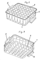
- Figures 2 and 3 show a depression part, consisting of a solid unit made of plastic, for instance, provided with a number of conical holes 2, each with an opening at the top and an opening at the bottom.
- the unit 1 is on two opposite sides provided with elastic stop members 5 and 6, each of which has a horizontal part attached to the depression part 1 and a vertical part with a contact part at its base and another part that constitutes a gripping part.
- the depression part 1 is intended to be placed in a bottom part 3, which is in the shape of a receptacle.
- the receptacle 3 is provided with a surrounding frame 7 intended to contact the inwardly-facing contact surfaces of the stop means 5 and 6.
- the receptacle is provided with openings 17 communication with the interior of the receptacle so that water can be supplied to the receptacle.
- the receptacle has a number of rod-shaped parts 8, the top end 4 of each being intended to form the bottom of a depression 2.
- the contact surfaces of the vertical part of the stop means will abut the surrounding frame 7 so that the top ends 4 of the pillar-shaped parts 8 will form the bottoms of each of the depressions 2 in the depression part 1.
- Cavities 10 are made beneath each pillar in the external bottom of the receptacle 3.
- a hood 11 is placed above the depression part 1.
- the hood is parallelepipedic and has a topside 12 provided with penetration members 13.
- the penetration members 13 are equal in number to the depressions 2 in the depression part 1. This means that the hood 11 can be turned upside down. Penetrations can be made in the depressions 2 and, when this has been done, the hood 11 is placed above the depression part 1. A greenhouse effect is obtained within the hood and the hood can be turned or removed for a short period to provide ventilation.
- the stop means 5 and 6 are made of elastic material and, if the vertical parts of the stop means 5 and 6 are moved outwardly, the depression part will descend, which results in the rod-shaped parts 8 being inserted inside the actual depressions 2.
- FIG. 8-12 it will be evident from Figure 8 that the depression part 1 has been filled with soil 18 and that the hood 11 has been turned upside down so that its penetration members 13 bore into the soil and achieve penetrations 19. Seeds 14 are then added to said penetrations. When this has been done, the hood 11 is turned over and, thanks to the hood, a certain greenhouse effect is then achieved above the soil surfaces in the depressions 2. Water can be supplied to the receptacle 3, as shown in Figure 13, by way of a hose 20 through the hole 17, which means that substantial auto-irrigation is achieved.
- Figure 11 shows how units in accordance with Figure 10 can be stacked one on top of another, the penetration members 13 being inserted into the cavities 10 in the bottom of the lower part 3.
- the vertical parts of the stop means 5 and 6 are influenced as shown in Figure 12, whereupon the depression part descends and the rods 8 are inserted into the through-running holes 2, upwardly displacing a conical lump of soil 16 with a plant 15 that is easy to grip and transplant, the conical lump of soil being firmly coherent.
- the present invention provides a very simple device for cultivating plants for transplanting in that each plant is grown in a conical hole with a bottom that is subsequently used to displace the conical lump of soil with the plant upwards.
- the cultivation and transplanting of plants cannot be effected in a simpler way.
- Figure 14 shows two units in accordance with the present invention stacked one on top of the other, illustrating that a relatively large number of units can be stacked in a small space and, furthermore, that water can be supplied to these units in a simple way so substantial auto-irrigation is achieved.
- the depression part as well as the bottom part and the hood, can be made of various materials and in various designs. This means, i.a., that the depression part need not even be solid.
Claims (9)
- Vorrichtung zur Wachstumsförderung von Saat bis zu einer Pflanze, die zur Umpflanzung vorgesehen ist, wobei die Vorrichtung einen Vertiefungsteil (1) mit einigen Vertiefungen (2) umfasst, von denen jede einen Querschnitt aufweist, dessen Größe von der Öffnung bis zum unteren Ende abnimmt, und die Durchflusslöcher bilden, einen Bodenteil (3), der mit dem Vertiefungsteil zusammenwirkt, und einige Einheiten (4), wobei jede Einheit den Boden einer Vertiefung (2) bildet und am Bodenteil (3) angeordnet ist, der in Bezug auf den Vertiefungsteil (1) in einer Weise beweglich ist, dass in einer Stellung die Einheiten (4) die Böden der Vertiefungen (2) bilden und in einer anderen Stellung in die Vertiefung eingeschoben sind, dadurch gekennzeichnet, dass der Bodenteil (3) die Form eines Behälters hat, der Vertiefungsteil (1) mit Hilfe der Anschlagelemente (5 bis 7) am oberen Rand des Behälters (3) aufliegen kann, so dass jede Einheit (4) den Boden einer Vertiefung (2) bilden kann, und der Vertiefungsteil (1) in den Behälter (3) abgesenkt werden kann, wenn die Anschlagelemente gelöst sind, so dass jede Einheit (4) eine Position im Inneren einer Vertiefung (2) einnimmt.
- Vorrichtung nach Anspruch 1, dadurch gekennzeichnet, dass jede Einheit (4) das freie Ende eines stabförmigen Teils (8) umfasst, der vom Boden des Behälters (3) aufragt.
- Vorrichtung nach Anspruch 2, dadurch gekennzeichnet, dass der Boden (9) des Behälters (3) an seiner Außenseite mit einer Vertiefung (10) unter jedem stabförmigen Teil (8) versehen ist.
- Vorrichtung nach Anspruch 1, dadurch gekennzeichnet, dass der obere Rand des Behälters (3) so beschaffen ist, dass Flüssigkeit in den Behälter (3) eingefüllt werden kann, wenn sich der Vertiefungsteil (1) und der Behälter (3) in der zusammengesetzten Stellung befinden.
- Vorrichtung nach irgendeinem der vorhergehenden Ansprüche, dadurch gekennzeichnet, dass eine Abdeckung (11) abnehmbar auf dem Vertiefungsteil (1) angeordnet werden kann, vorzugsweise so, dass alle Vertiefungsöffnungen abgedeckt sind.
- Vorrichtung nach Anspruch 5, dadurch gekennzeichnet, dass die Oberseite (12) der Abdeckung (11) eben und mit einer Anzahl von Eindruckelementen (13) versehen ist, die der Anzahl der Vertiefungen (2) entspricht.
- Vorrichtung nach Anspruch 6, dadurch gekennzeichnet, dass die Eindruckelemente (13) dafür vorgesehen sind, einen Eindruck in jeder gefüllten Vertiefung (2) zu schaffen, wobei dieser Eindruck für eine Saat vorgesehen ist.
- Vorrichtung nach Anspruch 3 und Anspruch 6, dadurch gekennzeichnet, dass die Eindruckelemente (13) dafür vorgesehen sind, mit Vertiefungen (10) an der Außenseite des Bodens (9) des Behälters (3) zusammenzuwirken, um ein festes Stapeln eines Behälters (3) auf einer Abdeckung (11) zu ermöglichen.
- Vorrichtung nach irgendeinem der vorhergehenden Ansprüche, dadurch gekennzeichnet, dass die Anschlagelemente (5 bis 7) einen Rahmen (7) umfassen, der am oberen Rand des Behälters (3) angebracht ist und mit nachfedernden Elementen (5, 6) zusammenwirkt, die am Vertiefungsteil (1) angebracht und dafür vorgesehen sind, den Rahmen (7) lösbar einrasten zu lassen.
Applications Claiming Priority (1)
| Application Number | Priority Date | Filing Date | Title |
|---|---|---|---|
| PCT/SE1998/001652 WO2000018215A1 (en) | 1998-09-16 | 1998-09-16 | Device for promoting growth from seed to plant |
Publications (2)
| Publication Number | Publication Date |
|---|---|
| EP1121013A1 EP1121013A1 (de) | 2001-08-08 |
| EP1121013B1 true EP1121013B1 (de) | 2003-02-26 |
Family
ID=20411273
Family Applications (1)
| Application Number | Title | Priority Date | Filing Date |
|---|---|---|---|
| EP98949266A Expired - Lifetime EP1121013B1 (de) | 1998-09-16 | 1998-09-16 | Vorrichtung zur wachstumsförderung von saat bis zu pflanze |
Country Status (6)
| Country | Link |
|---|---|
| US (1) | US6581329B1 (de) |
| EP (1) | EP1121013B1 (de) |
| AT (1) | ATE233043T1 (de) |
| AU (1) | AU9562298A (de) |
| DE (1) | DE69811747T2 (de) |
| WO (1) | WO2000018215A1 (de) |
Families Citing this family (9)
| Publication number | Priority date | Publication date | Assignee | Title |
|---|---|---|---|---|
| US8707618B2 (en) | 2007-01-15 | 2014-04-29 | Hortech, Inc. | Modular planting system for roof applications |
| US20080168710A1 (en) * | 2007-01-15 | 2008-07-17 | Mackenzie David S | Modular Planting System For Roof Applications |
| US20120137580A1 (en) * | 2009-07-09 | 2012-06-07 | Dekker Chrysanten B.V. | System, watering device and method for developing roots on plant cuttings |
| WO2011014933A1 (en) * | 2009-08-07 | 2011-02-10 | Nuplant Pty Ltd | Plantlet handling system |
| EP2575426B1 (de) * | 2010-06-07 | 2015-09-09 | Australian Growing Solutions Pty Ltd | Stapelbare container und entsprechendes verfahren für den transport von pflanzen |
| CN110476730B (zh) * | 2012-02-17 | 2022-07-12 | Oms投资公司 | 植物生长系统以及采用所述系统的方法 |
| US9265200B2 (en) | 2012-06-13 | 2016-02-23 | Bioroof Systems Inc. | Modular vegetated roof system |
| CN103814767A (zh) * | 2014-02-07 | 2014-05-28 | 兰州大学 | 苔藓植物实验材料快速培养装置 |
| DE102022106017A1 (de) | 2022-03-15 | 2023-09-21 | Pöppelmann Holding GmbH & Co. KG | Behälter und Verfahren zur In-Vitro-Pflanzenkultivierung |
Family Cites Families (7)
| Publication number | Priority date | Publication date | Assignee | Title |
|---|---|---|---|---|
| GB1229337A (de) * | 1969-04-10 | 1971-04-21 | ||
| US3606697A (en) * | 1969-08-22 | 1971-09-21 | Leopold Co Inc F B | Tray for seed germination and the like |
| US5419080A (en) * | 1991-02-01 | 1995-05-30 | Gardener's Supply | Multi-celled tray for growing plants |
| USD356524S (en) * | 1991-12-18 | 1995-03-21 | Drader Manufacturing Industries Ltd. | Seedling container |
| WO1996021346A1 (en) * | 1995-01-10 | 1996-07-18 | Synbra B.V. | Method, device and set of several hollow bodies for extracting a plug out of a hollow body |
| USD409947S (en) * | 1998-05-13 | 1999-05-18 | Emplast, Inc. | Seed germination tray and cover |
| USD419483S (en) * | 1998-10-30 | 2000-01-25 | Lee Valley Tools Ltd. | Seed starter unit |
-
1998
- 1998-09-16 DE DE69811747T patent/DE69811747T2/de not_active Expired - Lifetime
- 1998-09-16 US US09/763,327 patent/US6581329B1/en not_active Expired - Fee Related
- 1998-09-16 AU AU95622/98A patent/AU9562298A/en not_active Abandoned
- 1998-09-16 EP EP98949266A patent/EP1121013B1/de not_active Expired - Lifetime
- 1998-09-16 WO PCT/SE1998/001652 patent/WO2000018215A1/en active IP Right Grant
- 1998-09-16 AT AT98949266T patent/ATE233043T1/de not_active IP Right Cessation
Also Published As
| Publication number | Publication date |
|---|---|
| EP1121013A1 (de) | 2001-08-08 |
| DE69811747D1 (de) | 2003-04-03 |
| WO2000018215A1 (en) | 2000-04-06 |
| DE69811747T2 (de) | 2004-03-18 |
| US6581329B1 (en) | 2003-06-24 |
| ATE233043T1 (de) | 2003-03-15 |
| AU9562298A (en) | 2000-04-17 |
Similar Documents
| Publication | Publication Date | Title |
|---|---|---|
| US5419080A (en) | Multi-celled tray for growing plants | |
| KR102080750B1 (ko) | 인삼재배용 수경재배 화분 | |
| EP1121013B1 (de) | Vorrichtung zur wachstumsförderung von saat bis zu pflanze | |
| CA2017945C (en) | Seedling container | |
| CN205357347U (zh) | 植物栽培装置 | |
| JPH01231826A (ja) | 水耕栽培方法及び装置 | |
| KR101698112B1 (ko) | 격자형 셀이 형성된 육묘 상자 및 블록매트형 상토를 포함하는 육묘 장치 | |
| CN209994957U (zh) | 育苗容器以及育苗装置 | |
| CN211607553U (zh) | 育苗钵营养土限位装置 | |
| KR101911203B1 (ko) | 식물 재배관리기 | |
| WO2020098781A1 (zh) | 育苗容器、育苗装置及育苗方法 | |
| JPH1189688A (ja) | 植木鉢積み重ね用ポールと植木鉢およびそれに用いられる給水用器具 | |
| KR102045705B1 (ko) | 생육활성화가 가능한 이식용 식물재배관리기 | |
| KR200493718Y1 (ko) | 식물 재배용 파이프형 화분 | |
| JPH0427312Y2 (de) | ||
| JP2000262151A (ja) | 植木鉢・プランター | |
| KR200199950Y1 (ko) | 육묘용 포트 | |
| JPH10113073A (ja) | 育苗方法 | |
| KR20230016115A (ko) | 지피포트를 이용한 저면관수식 육묘방법 및 저면관수장치 | |
| JP2796792B2 (ja) | ヤマノイモの栽培器具およびその栽培方法 | |
| KR200329591Y1 (ko) | 육묘용 포트 받침 | |
| JPH0444059Y2 (de) | ||
| JPH0365Y2 (de) | ||
| JPH0123254Y2 (de) | ||
| KR970002364Y1 (ko) | 채소육묘자동탈피포트(pot) |
Legal Events
| Date | Code | Title | Description |
|---|---|---|---|
| PUAI | Public reference made under article 153(3) epc to a published international application that has entered the european phase |
Free format text: ORIGINAL CODE: 0009012 |
|
| 17P | Request for examination filed |
Effective date: 20010215 |
|
| AK | Designated contracting states |
Kind code of ref document: A1 Designated state(s): AT BE CH CY DE DK ES FI FR GB GR IE IT LI LU MC NL PT SE |
|
| GRAG | Despatch of communication of intention to grant |
Free format text: ORIGINAL CODE: EPIDOS AGRA |
|
| 17Q | First examination report despatched |
Effective date: 20020528 |
|
| GRAG | Despatch of communication of intention to grant |
Free format text: ORIGINAL CODE: EPIDOS AGRA |
|
| GRAH | Despatch of communication of intention to grant a patent |
Free format text: ORIGINAL CODE: EPIDOS IGRA |
|
| GRAH | Despatch of communication of intention to grant a patent |
Free format text: ORIGINAL CODE: EPIDOS IGRA |
|
| GRAA | (expected) grant |
Free format text: ORIGINAL CODE: 0009210 |
|
| RIN1 | Information on inventor provided before grant (corrected) |
Inventor name: ERIKSSON, ALBERT |
|
| AK | Designated contracting states |
Designated state(s): AT BE CH CY DE DK ES FI FR GB GR IE IT LI LU MC NL PT SE |
|
| PG25 | Lapsed in a contracting state [announced via postgrant information from national office to epo] |
Ref country code: NL Free format text: LAPSE BECAUSE OF FAILURE TO SUBMIT A TRANSLATION OF THE DESCRIPTION OR TO PAY THE FEE WITHIN THE PRESCRIBED TIME-LIMIT Effective date: 20030226 Ref country code: LI Free format text: LAPSE BECAUSE OF FAILURE TO SUBMIT A TRANSLATION OF THE DESCRIPTION OR TO PAY THE FEE WITHIN THE PRESCRIBED TIME-LIMIT Effective date: 20030226 Ref country code: IT Free format text: LAPSE BECAUSE OF FAILURE TO SUBMIT A TRANSLATION OF THE DESCRIPTION OR TO PAY THE FEE WITHIN THE PRESCRIBED TIME-LIMIT;WARNING: LAPSES OF ITALIAN PATENTS WITH EFFECTIVE DATE BEFORE 2007 MAY HAVE OCCURRED AT ANY TIME BEFORE 2007. THE CORRECT EFFECTIVE DATE MAY BE DIFFERENT FROM THE ONE RECORDED. Effective date: 20030226 Ref country code: GR Free format text: LAPSE BECAUSE OF FAILURE TO SUBMIT A TRANSLATION OF THE DESCRIPTION OR TO PAY THE FEE WITHIN THE PRESCRIBED TIME-LIMIT Effective date: 20030226 Ref country code: FI Free format text: LAPSE BECAUSE OF FAILURE TO SUBMIT A TRANSLATION OF THE DESCRIPTION OR TO PAY THE FEE WITHIN THE PRESCRIBED TIME-LIMIT Effective date: 20030226 Ref country code: CH Free format text: LAPSE BECAUSE OF FAILURE TO SUBMIT A TRANSLATION OF THE DESCRIPTION OR TO PAY THE FEE WITHIN THE PRESCRIBED TIME-LIMIT Effective date: 20030226 Ref country code: BE Free format text: LAPSE BECAUSE OF FAILURE TO SUBMIT A TRANSLATION OF THE DESCRIPTION OR TO PAY THE FEE WITHIN THE PRESCRIBED TIME-LIMIT Effective date: 20030226 Ref country code: AT Free format text: LAPSE BECAUSE OF FAILURE TO SUBMIT A TRANSLATION OF THE DESCRIPTION OR TO PAY THE FEE WITHIN THE PRESCRIBED TIME-LIMIT Effective date: 20030226 |
|
| REG | Reference to a national code |
Ref country code: GB Ref legal event code: FG4D |
|
| REG | Reference to a national code |
Ref country code: CH Ref legal event code: EP |
|
| REG | Reference to a national code |
Ref country code: IE Ref legal event code: FG4D |
|
| REF | Corresponds to: |
Ref document number: 69811747 Country of ref document: DE Date of ref document: 20030403 Kind code of ref document: P |
|
| PG25 | Lapsed in a contracting state [announced via postgrant information from national office to epo] |
Ref country code: SE Free format text: LAPSE BECAUSE OF FAILURE TO SUBMIT A TRANSLATION OF THE DESCRIPTION OR TO PAY THE FEE WITHIN THE PRESCRIBED TIME-LIMIT Effective date: 20030526 Ref country code: PT Free format text: LAPSE BECAUSE OF FAILURE TO SUBMIT A TRANSLATION OF THE DESCRIPTION OR TO PAY THE FEE WITHIN THE PRESCRIBED TIME-LIMIT Effective date: 20030526 Ref country code: DK Free format text: LAPSE BECAUSE OF FAILURE TO SUBMIT A TRANSLATION OF THE DESCRIPTION OR TO PAY THE FEE WITHIN THE PRESCRIBED TIME-LIMIT Effective date: 20030526 |
|
| NLV1 | Nl: lapsed or annulled due to failure to fulfill the requirements of art. 29p and 29m of the patents act | ||
| PG25 | Lapsed in a contracting state [announced via postgrant information from national office to epo] |
Ref country code: ES Free format text: LAPSE BECAUSE OF FAILURE TO SUBMIT A TRANSLATION OF THE DESCRIPTION OR TO PAY THE FEE WITHIN THE PRESCRIBED TIME-LIMIT Effective date: 20030828 |
|
| PG25 | Lapsed in a contracting state [announced via postgrant information from national office to epo] |
Ref country code: LU Free format text: LAPSE BECAUSE OF NON-PAYMENT OF DUE FEES Effective date: 20030916 Ref country code: IE Free format text: LAPSE BECAUSE OF NON-PAYMENT OF DUE FEES Effective date: 20030916 Ref country code: CY Free format text: LAPSE BECAUSE OF FAILURE TO SUBMIT A TRANSLATION OF THE DESCRIPTION OR TO PAY THE FEE WITHIN THE PRESCRIBED TIME-LIMIT Effective date: 20030916 |
|
| PG25 | Lapsed in a contracting state [announced via postgrant information from national office to epo] |
Ref country code: MC Free format text: LAPSE BECAUSE OF NON-PAYMENT OF DUE FEES Effective date: 20030930 |
|
| ET | Fr: translation filed | ||
| PLBE | No opposition filed within time limit |
Free format text: ORIGINAL CODE: 0009261 |
|
| STAA | Information on the status of an ep patent application or granted ep patent |
Free format text: STATUS: NO OPPOSITION FILED WITHIN TIME LIMIT |
|
| 26N | No opposition filed |
Effective date: 20031127 |
|
| REG | Reference to a national code |
Ref country code: IE Ref legal event code: MM4A |
|
| PGFP | Annual fee paid to national office [announced via postgrant information from national office to epo] |
Ref country code: DE Payment date: 20130904 Year of fee payment: 16 |
|
| PGFP | Annual fee paid to national office [announced via postgrant information from national office to epo] |
Ref country code: FR Payment date: 20130919 Year of fee payment: 16 Ref country code: GB Payment date: 20130909 Year of fee payment: 16 |
|
| REG | Reference to a national code |
Ref country code: DE Ref legal event code: R119 Ref document number: 69811747 Country of ref document: DE |
|
| GBPC | Gb: european patent ceased through non-payment of renewal fee |
Effective date: 20140916 |
|
| REG | Reference to a national code |
Ref country code: FR Ref legal event code: ST Effective date: 20150529 |
|
| PG25 | Lapsed in a contracting state [announced via postgrant information from national office to epo] |
Ref country code: GB Free format text: LAPSE BECAUSE OF NON-PAYMENT OF DUE FEES Effective date: 20140916 Ref country code: DE Free format text: LAPSE BECAUSE OF NON-PAYMENT OF DUE FEES Effective date: 20150401 |
|
| PG25 | Lapsed in a contracting state [announced via postgrant information from national office to epo] |
Ref country code: FR Free format text: LAPSE BECAUSE OF NON-PAYMENT OF DUE FEES Effective date: 20140930 |