EP1120628A1 - Gekühlte Messbalken an Walzen eines Walzgerüsts beim Walzvorgang - Google Patents
Gekühlte Messbalken an Walzen eines Walzgerüsts beim Walzvorgang Download PDFInfo
- Publication number
- EP1120628A1 EP1120628A1 EP01100829A EP01100829A EP1120628A1 EP 1120628 A1 EP1120628 A1 EP 1120628A1 EP 01100829 A EP01100829 A EP 01100829A EP 01100829 A EP01100829 A EP 01100829A EP 1120628 A1 EP1120628 A1 EP 1120628A1
- Authority
- EP
- European Patent Office
- Prior art keywords
- measuring bar
- measuring
- temperature
- distance
- temperature shield
- Prior art date
- Legal status (The legal status is an assumption and is not a legal conclusion. Google has not performed a legal analysis and makes no representation as to the accuracy of the status listed.)
- Granted
Links
- 238000005096 rolling process Methods 0.000 title claims description 17
- 238000011156 evaluation Methods 0.000 claims abstract description 4
- 239000002826 coolant Substances 0.000 claims description 36
- 238000007789 sealing Methods 0.000 claims description 25
- 239000000463 material Substances 0.000 claims description 12
- 238000005452 bending Methods 0.000 claims description 8
- 239000012528 membrane Substances 0.000 claims description 7
- 239000011810 insulating material Substances 0.000 claims description 6
- 239000002184 metal Substances 0.000 claims description 4
- 239000007769 metal material Substances 0.000 claims description 4
- 230000003287 optical effect Effects 0.000 claims description 3
- 238000012856 packing Methods 0.000 claims description 3
- 238000003860 storage Methods 0.000 claims description 3
- 238000011144 upstream manufacturing Methods 0.000 claims description 3
- 239000004035 construction material Substances 0.000 claims description 2
- 239000000112 cooling gas Substances 0.000 claims description 2
- 238000001914 filtration Methods 0.000 abstract 1
- 230000010358 mechanical oscillation Effects 0.000 abstract 1
- 238000005259 measurement Methods 0.000 description 13
- 230000000694 effects Effects 0.000 description 5
- 239000007788 liquid Substances 0.000 description 5
- 238000009826 distribution Methods 0.000 description 4
- 230000008859 change Effects 0.000 description 3
- 238000001816 cooling Methods 0.000 description 3
- 238000010438 heat treatment Methods 0.000 description 3
- 238000000034 method Methods 0.000 description 3
- 230000005855 radiation Effects 0.000 description 3
- 238000013461 design Methods 0.000 description 2
- 238000010586 diagram Methods 0.000 description 2
- 210000004907 gland Anatomy 0.000 description 2
- 238000009434 installation Methods 0.000 description 2
- 230000008569 process Effects 0.000 description 2
- 230000002123 temporal effect Effects 0.000 description 2
- 238000012546 transfer Methods 0.000 description 2
- 238000005352 clarification Methods 0.000 description 1
- 238000012790 confirmation Methods 0.000 description 1
- 230000001276 controlling effect Effects 0.000 description 1
- 239000000110 cooling liquid Substances 0.000 description 1
- 230000003467 diminishing effect Effects 0.000 description 1
- 230000005672 electromagnetic field Effects 0.000 description 1
- 230000007613 environmental effect Effects 0.000 description 1
- 230000002349 favourable effect Effects 0.000 description 1
- 239000007789 gas Substances 0.000 description 1
- 230000006872 improvement Effects 0.000 description 1
- 238000009413 insulation Methods 0.000 description 1
- 238000004519 manufacturing process Methods 0.000 description 1
- 238000012986 modification Methods 0.000 description 1
- 230000004048 modification Effects 0.000 description 1
- 210000000056 organ Anatomy 0.000 description 1
- 230000035699 permeability Effects 0.000 description 1
- 230000001105 regulatory effect Effects 0.000 description 1
- 239000005871 repellent Substances 0.000 description 1
- 239000007921 spray Substances 0.000 description 1
- 230000006641 stabilisation Effects 0.000 description 1
- 238000011105 stabilization Methods 0.000 description 1
- 230000001629 suppression Effects 0.000 description 1
- 238000012549 training Methods 0.000 description 1
- 238000010792 warming Methods 0.000 description 1
- 238000009736 wetting Methods 0.000 description 1
Images

Classifications
-
- B—PERFORMING OPERATIONS; TRANSPORTING
- B21—MECHANICAL METAL-WORKING WITHOUT ESSENTIALLY REMOVING MATERIAL; PUNCHING METAL
- B21B—ROLLING OF METAL
- B21B38/00—Methods or devices for measuring, detecting or monitoring specially adapted for metal-rolling mills, e.g. position detection, inspection of the product
- B21B38/12—Methods or devices for measuring, detecting or monitoring specially adapted for metal-rolling mills, e.g. position detection, inspection of the product for measuring roll camber
-
- G—PHYSICS
- G01—MEASURING; TESTING
- G01B—MEASURING LENGTH, THICKNESS OR SIMILAR LINEAR DIMENSIONS; MEASURING ANGLES; MEASURING AREAS; MEASURING IRREGULARITIES OF SURFACES OR CONTOURS
- G01B21/00—Measuring arrangements or details thereof, where the measuring technique is not covered by the other groups of this subclass, unspecified or not relevant
- G01B21/20—Measuring arrangements or details thereof, where the measuring technique is not covered by the other groups of this subclass, unspecified or not relevant for measuring contours or curvatures, e.g. determining profile
Definitions
- the invention relates to a device for measurement the contour, the horizontal curvature and / or the horizontal Position of a roll of a roll stand, with contactless working distance sensors, by means of which a distance to the outer surface of the roller can be measured without contact.
- the invention has for its object the above Device for measuring the contour, the horizontal Curvature and / or the horizontal position of a roller of a rolling stand in such a way that it can be Arranged near the work rolls of a roll stand can be that they are from a fixed measuring base Distance to the roller surface can measure and so, largely unaffected by coolant and temperature influences, a position, deformation and wear measurement the work rolls allowed.
- the Device for measuring the contour, the horizontal curvature and / or the horizontal position of the work roll at least has a measuring bar that is parallel to the roller in one fixed distance from this is arranged and at which several Non-contact distance sensors in the axial direction of the measuring bar are arranged at a distance from one another.
- the non-contact distance measurement between the work roll and the non-contact person working in the room Distance sensors are more meaningful for the creation Measured values are particularly suitable, especially under certain conditions Temperature and distance influences in the measurement signal can be separated.
- the arrangement of the contactless working distance sensors takes place in the immediate vicinity the roller to be examined.
- the temperature sensor for recording temperatures on the measuring bar and has evaluation electronics by means of the one based on that of the temperature sensors detected thermal values determined thermal bending of the Measuring bar can be compensated, may also result from it resulting falsifications of a measurement signal from the distance sensors be compensated.
- Vibrations of the measuring bar can be eliminated be a filter device by the measuring bar is assigned by means of the mechanical vibrations of the Measuring bar can be suppressed in a measurement signal. According to the invention it is thus excluded that the distance sensors any measuring signals originating from the measuring bar Disorders subject to deformation due to geometrical uneven and time-varying heating of the measuring bar go back. Furthermore, it is according to the invention possible to calculate any movements of the rollers eliminate.
- Each measuring bar of the device according to the invention can at least three, e.g. five, distance sensors.
- the distance between the measuring bar and the roller surface of several distance sensors across the roll width non-contact during and outside the rolling process be measured.
- the thermal Change in diameter, the curvature of the roller axis and / or the position of the roller can be determined.
- the device according to the invention expediently has two or three measuring bars that are offset from one another on the circumference the roller are arranged. With three measuring bars next to the Roll contour the exact position of the roll and the spatial Curvature of the roller axis can be determined in space, whereas in contrast, with two or one measuring bar only limited Statements are possible.
- the measuring bar can be moved in the direction of the Rolled material strip arranged upstream and downstream of the work roll his.
- the device according to the invention can the upper work roll a roll stand or the lower work roll of a roll stand be assigned. Of course it is possible, both for the upper work roll and for the lower work roll of a roll stand each one according to the invention To provide device.
- each measuring bar and the are expedient Axes of the distance sensors of the respective measuring bar in arranged on a plane, wherein the advantageous active end faces of the distance sensors the same Should be at a distance from the axis of the measuring bar.
- the measuring bars of the device according to the invention are parallel to the roller axis in free space above or below the rolling stock level in front of and behind the work roll.
- the respective device swivels or moves the area of the chock contour and depending on the size of the delivery and the current one
- the distance sensors always have the same diameter Clearance on the roller surface.
- each measuring bar equipped with several distance sensors to be provided with a distortion stabilization, by means of which can be guaranteed that thermal effects will not lead to a change in the position of the sensor line in the room, it is useful if each measuring bar has a surrounding one Temperature shield is provided. This can each measuring beam carrying several distance sensors in front of direct thermal deformation due to one-sided and temporal variable heating and cooling by one this temperature shield formed the heat transfer obstructing umbrella.
- the measuring bar and / or the temperature shield advantageously point Pipe cross-section.
- the temperature shield on the outer surface of the measuring bar sits and as an insulating layer of an elastic or easily deformable and heat-insulating material is, on the one hand, a temperature protection of the actual Measuring bar can be realized, whereby also on the Insulating layer occurring on their temperature load diminishing dimensional changes do not affect the actual Measuring bars are transmitted.
- this can have a cavity inside have through which a cooling medium can be passed.
- the temperature shield surrounds the measuring bar with training of a gap with a gap.
- the measuring bar is designed as a thin-walled tube, on a bearing journal is attached to each of its two ends by means of which the measuring bar can be stored or held, there is a profile for the actual measuring bar high bending stiffness and low weight. The deformations of the measuring beam as a result of the load caused by its Dead weight is thus minimized.
- the distance between the outer surface is expedient of the tube of the measuring bar and the inner surface of the temperature shield forming outer tube constant.
- the holder of the temperature shield on the measuring bar can also realized using metallic support and sealing membranes become.
- the temperature shielding can also be preferably carried out non-metallic gland packing on the measuring bar be supported.
- Temperature shielding is also advantageous the bearing device holding the measuring bar by a elastic sealing device connected to the gap space between the inner surface of the temperature shield and the Seals the outer surface of the measuring beam to the outside.
- the elastic sealing device can advantageously be made of sealing sleeves be trained with on one side the temperature shield and on its other side with the the measuring device supporting bearing device are connected.
- the elastic sealing device made of sealing rings be formed, the inner circumference of which with the measuring bar holding bearing device and its outer circumference the temperature shield is in place.
- the sealing rings can advantageously be used as O-rings or shaft sealing rings be trained.
- They can be made of an elastic metallic material or made of an elastic non-metallic material his.
- the gap between the outer surface of the measuring bar and the inner surface of the temperature shield can be advantageous flows through a gaseous or liquid cooling medium be, whereby a uniform temperature distribution in the or on the measuring bar and the cause of thermal justified curvature of the measuring bar due to one-sided Warming can be omitted.
- each measuring bar advantageously has one window for each distance sensor of the relevant measuring bar on, which preferably by means of a cover from a electrically non-conductive or translucent material is closed in a fluid-tight manner.
- the covers of the windows can expediently be designed as membranes. This ensures a local permeability of the temperature shield forming tube for an electromagnetic Field or created for light, what as eddy current sensors or designed as optical sensors without contact working distance sensors is essential.
- the coolant can Uniformization and keeping the temperature of the Measuring bar to be flowed past this planned.
- the guide not with both the measuring bar and the Temperature shield is connected.
- the Guide attached to the measuring beam and in relation to the Temperature shielding be designed without contact or but attached to the temperature shield and in relation to the measuring bar should be designed without contact.
- the measuring bar can be made of a common construction material or from a material with an extremely low coefficient of thermal expansion be trained.
- the temperature shield can be single-walled a homogeneous material or multi-walled from a combination of materials, e.g. made of a metal and a heat-insulating Material.
- Connection cables for the distance sensors can be connected axially or guided radially in the measuring beam opening become.
- Measuring method serves a distance measurement between the Roller surface and each carrying several distance sensors Measuring bar and the suppression of measurement errors thermal deformation of the measuring beam as actual Sensor support organs due to unilateral and temporally variable Heating and cooling by means of a heat-repellent or heat-insulating outer temperature shield and a device for cooling and guarantee more extensive Temperature stability of the measuring bars.
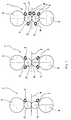
- FIG. 1 In each of the three basic representations of FIG. 1 there is one Roll stand 1 shown, which is part of a in other rolling mill not shown in the FIGURES or Rolling mill forms.
- the roll stand 1 has an upper work roll 2 by a upper backup roll 3 is supported, and a lower work roll 4, which is supported by a lower backup roller 5.
- the upper work roll 2 and the lower work roll 4 each with one Device according to the invention for measuring the contour of the horizontal curvature and / or the horizontal position of the respective work roll 2 or 4 equipped. Since the two devices according to the invention with regard to their Arrangement, function and effect correspond to the following only that according to the invention assigned to the upper work roll 2 Device described.
- the device includes a measuring bar 7 Longitudinal axis parallel to the longitudinal axis of the upper work roll 2 is arranged. Between the outer surface of the measuring bar 7 and the outer shell of the upper work roll 2 is always on Distance provided so that by means of the measuring bar 7 in the Axially spaced apart, in FIG. 1 Distance sensors (not shown) that work without contact the distance to the outer surface of the work roll 2 in Operation of the roll stand 1 is continuously detectable.
- the one used in the middle roll stand 1 in FIG. 1 differs from the above described device in that two measuring bars 7 are provided, of which one in the direction of the Rolled material strip 6 upstream of the upper work roll 2 and the others in the running direction of the rolled strip 6 downstream of the upper one Work roll 2 is arranged.
- two measuring bars 7 are provided, of which one in the direction of the Rolled material strip 6 upstream of the upper work roll 2 and the others in the running direction of the rolled strip 6 downstream of the upper one Work roll 2 is arranged.
- the lower support roller 5 of the middle roll stand in FIG. 1 1 associated device designed.
- measuring bars 7 each according to the invention
- the device is in principle arbitrary, but is used in In individual cases through the requirements for the desired statements certainly.
- a measurement by three measuring bars 7 ensures an optimal determination of the contour, the horizontal Position and the horizontal curvature of the roll axis of the upper work roll 2 or lower work roll 4.
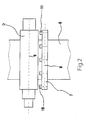
- Non-contact distance sensors 10 On the outer surface of the measuring bar 7 in FIG illustrated embodiment five non-contact working Distance sensors 10 arranged in the operation of the roll stand 1 the distance between their radiation surfaces and the these opposite sections of the outer surface the upper work roll 2 can continuously capture.
- the Non-contact distance sensors 10 can e.g. as Eddy current sensors or designed as optical sensors his.
- the Distance sensors 10 provided on the measuring bar 7 with one another are equally spaced. Furthermore, they are on the measuring bar 7 arranged distance sensors 10 transversely to the direction of travel of the rolled strip 6 symmetrical to the rolled strip center and arranged to the middle of the upper work roll 2.
- the two on Measuring bars 7 are located outside distance sensors 10 out of the track of the rolled strip 6. On the base of those formed by these two outer distance sensors 10 Measuring points can thus be a relative measurement of the between them area of the outer lateral surface located at both measuring points the upper work roll 2 are made.
- the measuring bar 7 can have a compensation device or be assigned to a compensation device, the temperature sensors to record the temperature on the measuring bar 7 and has evaluation electronics, by means of which one based on the temperature values recorded by the temperature sensors determined thermal bending of the measuring beam 7 is compensable. Furthermore, the measuring bar 7 can have a Filter device can be assigned by means of the mechanical Vibrations of the measuring bar 7 in the measuring signal of the distance sensors 10 can be suppressed.
- the longitudinal axis 8 of the measuring bar 7 and the axes 11 of the Distance sensors 10 of the measuring bar 7 are in one plane arranged.
- the active end faces or radiation surfaces of the Distance sensors 10 have the same distance from the longitudinal axis 8 of the measuring bar 7.
- the measuring bar 7 is in relation to the work roll 2, 3 pivotally or movably supported, by means of its two lateral support points and holding devices by means of which it pivots or movable and always in compliance with a predetermined Distance between its distance sensors 10 and Roll surface of the work roll 2, 3 depending on the infeed and the current diameter of the work roll 2, 3 can be aligned.
- the measuring bar 7 can, as shown in FIG Embodiment emerges with a temperature shield 12 be provided.
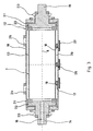
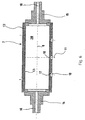
- the measuring bar 7 consists of the one in FIG. 3 illustrated embodiment from a thin-walled tube 13, provided at both ends with trunnions 14, 15 is.
- bearing pin 14 is separably connected to the thin-walled tube 13.
- This journal 14 has an axial bore 16, which coaxially to the longitudinal axis 8 of the measuring beam 7 and the thin-walled tube 13 extends.
- This axial bore 16 serves as a cable entry for the wiring of the distance sensors 10 serving line branches, not shown in FIG. 3.
- the thin-walled tube 13 is on its outer surface Eyes 17 provided on which the distance sensors 10 of the Measuring bar 7 are attached.
- the wiring of the distance sensors 10 takes place by in the radial direction of the measuring bar 7 or the thin-walled tube 13 and the eyes extending Recesses 18.
- the outer thin-walled tube 19 has at both ends each have an end section 21 with a thicker cross section on the inner surface of which a narrow support or Bearing collar 22 is formed on the corresponding Bearing pins 14 and 15, respectively, of the two bearing pins 14, 15 formed storage device of the measuring beam 7 or the thin-walled Tube 13 rests.
- the narrowness of the support or Bearing bundles 22 and the loose bearing of these bearing bundles 22 ensures a sliding and a bending moment-free connection between the outer thin-walled tube 18 and the inner thin-walled tube 13.
- an elastic sealing sleeve 23 provided by means of which the annular gap space 20 between the outer thin-walled tube 19 and the inner thin-walled tube 13 is sealed from the environment.
- the outer thin wall forming the temperature shield 12 Tube 19 has a cooling medium inlet designed as an inlet connection 24 in the area of one end and one as Return pipe 25 trained coolant drain in the area the other end.
- a suitable coolant in the gap 20 between the two pipes 13, 19 arranged coaxially to one another are introduced, which has an even temperature distribution on the inside Ensure thin-walled tube 13 of the measuring beam 7 should. This coolant is through the return 25 from the Gap space 20 removed.
- distance sensors 10 In the area of on the outer surface of the thin-walled Pipe 13 of the measuring bar 7 arranged distance sensors 10 is the outer thin-walled tube 19 of the temperature shield 12 provided with windows 26. Through the window 26 can Distance sensors 10 of the measuring bar 7 the distance to the lateral surface the work roll 2 or 3.
- the windows 26 are in the embodiment shown in FIG Membranes 27 closed, depending on the design of the distance sensors 10 from an electrically non-conductive or translucent material are formed.
- the Membranes 27 are the windows 26 in the outer thin-walled tube 19 of the temperature shield 12 liquid and gas tight locked.
- Embodiments of the measuring bar 7 supporting and sealing Metal membranes or e.g. non-metallic packing glands be provided by means of which a movable and Bending moment free connection between the measuring beam 7 and the Temperature shield 12 or the inner thin-walled tube 13 of the measuring beam 7 and the outer thin-walled tube 19 of the Temperature shield 12 can be realized.
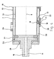
- the measuring bar shown in FIG. 4 with its left half 7 basically has the same structure as that above Hand of FIG 3 measuring beam 7.
- the sealing of the Gap 20 between the inner thin-walled tube 13 of the Measuring bar 7 and the outer thin-walled tube 19 of the temperature shield 12 takes place in that shown in FIG Embodiment by an elastic sealing ring 28, the can be designed as an O-ring or shaft seal.
- On the corresponding elastic sealing ring 28 is also shown in FIG. 4 Right end of the measuring beam 7, not shown, is provided.
- Through the elastic sealing rings 28 can The embodiment of the measuring bar 7 shown in FIG. 4 the elastic sealing sleeves 23 of the one shown in FIG Measuring bar 7 to be replaced.
- This guide device 29 is in the gap 20 between the outer thin-walled, not shown in FIG 5 Tube 19 of the temperature shield 12 and that in FIG. 5 inner thin-walled tube 13 of the measuring bar 7 shown arranged.
- This guide device 29 one should be as possible uniform temperature distribution inside thin-walled Tube 13 of the measuring beam 7 can be guaranteed.
- the embodiment of the guide device 29 shown in FIG. 5 is helical and on the outer surface of the inner thin-walled tube 13 of the measuring beam 7 attached.
- Coolant which is designed as a cooling liquid or as a cooling gas can be evenly along the outer surface of the inner thin-walled tube 13 out before it the gap space 20 leaves through the return pipe 25 again.
- the temperature shield 12 is an insulating layer made of a heat-insulating Material formed, this heat insulating material is elastic or easily deformable.
- Pipe profiles can also be designed in a different way, whereby the concrete design of the tube profiles from the concrete Result in installation position of the measuring beam 7; for example such profiles more favorable deformation properties as a result own their own mass.
Landscapes
- Engineering & Computer Science (AREA)
- Mechanical Engineering (AREA)
- Physics & Mathematics (AREA)
- General Physics & Mathematics (AREA)
- Length Measuring Devices With Unspecified Measuring Means (AREA)
- Coating Apparatus (AREA)
- Coating With Molten Metal (AREA)
Abstract
Description
- FIG 1
- Prinzipdarstellungen für drei unterschiedliche Ausführungsformen der erfindungsgemäßen Vorrichtung an einem Walzgerüst;
- FIG 2
- eine Prinzipdarstellung der Anordnung berührungslos arbeitener Abstandssensoren an einem Messbalken der erfindungsgemäßen Vorrichtung;
- FIG 3
- eine erste Ausführungsform eines mit einer Wärmeabschirmung versehenen Messbalkens einer erfindungsgemäßen Vorrichtung;
- FIG 4
- eine weitere Ausführungsform eines mit einer Wärmeabschirmung versehenen Messbalkens einer erfindungsgemäßen Vorrichtung;
- FIG 5
- eine Prinzipdarstellung einer Leiteinrichtung für ein Kühlmedium an einem Messbalken einer erfindungsgemäßen Vorrichtung; und
- FIG 6
- eine weitere Ausführungsform eines Messbalkens einer erfindungsgemäßen Vorrichtung.
Claims (57)
- Vorrichtung zur Messung der Kontur, der horizontalen Krümmung und/oder der horizontalen Position einer Walze (2, 3) eines Walzgerüsts (1), mit berührungslos arbeitenden Abstandssensoren (10, mittels denen ein Abstand zur Mantelfläche der Walze (2, 3) berührungsfrei messbar ist, gekennzeichnet durch zumindest einen Messbalken (7), der parallel zur Walze (2, 3) in einem festen Abstand zu dieser angeordnet ist und an dem mehrere Abstandssensoren (10) in seiner Axialrichtung zueinander beabstandet angeordnet sind.
- Vorrichtung nach Anspruch 1, bei der dem Messbalken (7) eine Kompensationseinrichtung zugeordnet ist, die Temperaturfühler zur Erfassung von Temperaturen am Messbalken (7) und eine Auswerteelektronik aufweist, mittels der eine auf der Grundlage der von den Temperaturfühlern erfassten Temperaturwerten ermittelte thermische Biegung des Messbalkens (7) kompensierbar ist.
- Vorrichtung nach Anspruch 1 oder 2, bei der dem Messbalken (7) eine Filtereinrichtung zugeordnet ist, mittels der mechanische Schwingungen des Messbalkens (7) in einem Messsignal unterdrückbar sind.
- Vorrichtung nach einem der Ansprüche 1 bis 3, bei der jeder Messbalken (7) zumindest drei Abstandssensoren (10) aufweist.
- Vorrichtung nach einem der Ansprüche 1 bis 4, die zwei oder drei Messbalken (7) aufweist, die zueinander versetzt am Umfang der Walze (2, 3) angeordnet sind.
- Vorrichtung nach einem der Ansprüche 1 bis 5, bei der die Messbalken (7) in Laufrichtung des Walzgutbandes (6) stromauf und stromab der Arbeitswalze (2, 3) angeordnet sind.
- Vorrichtung nach einem der Ansprüche 1 bis 6, bei der die Messbalken (7) unter unterschiedlichen Winkeln zur Walzgutebene (6) angeordnet sind.
- Vorrichtung nach einem der Ansprüche 1 bis 7, die einer oberen Arbeitswalze (2) eines Walzgerüsts (1) zugeordnet ist.
- Vorrichtung nach einem der Ansprüche 1 bis 7, die einer unteren Arbeitswalze (4) eines Walzgerüsts (1) zugeordnet ist.
- Vorrichtung nach einem der Ansprüche 1 bis 9, von der eine der oberen (2) und eine zweite der unteren Arbeitswalze (4) eines Walzgerüsts (1) zugeordnet sind.
- Vorrichtung nach einem der Ansprüche 1 bis 10, die jeweils an Arbeitswalzen (2, 3), z.B. an allen oberen und/ oder allen unteren Arbeitswalzen (2, 3) unterschiedlicher Walzgerüste (1) einer Walzstraße vorgesehen ist.
- Vorrichtung nach einem der Ansprüche 1 bis 11, bei der die an einem Messbalken (7) angeordneten Abstandssensoren (10) untereinander gleichbeabstandet sind.
- Vorrichtung nach einem der Ansprüche 1 bis 12, bei der die an einem Messbalken (7) angeordneten Abstandssensoren (10) quer zur Laufrichtung des Walzgutbandes (6) symmetrisch zur Walzgutband- und zur Walzenmitte angeordnet sind.
- Vorrichtung nach einem der Ansprüche 1 bis 13, bei der zumindest die beiden äußeren Abstandssensoren (10) außerhalb der Walzgutbandspur angeordnet sind.
- Vorrichtung nach einem der Ansprüche 1 bis 14, bei der die Achse (8) jedes Messbalkens (7) und die Achsen der Abstandssensoren (10) des jeweiligen Messbalkens (7) in einer Ebene angeordnet sind.
- Vorrichtung nach einem der Ansprüche 1 bis 15, bei der die aktiven Stirnflächen der Abstandssensoren (10) den gleichen Abstand zur Achse (8) des Messbalkens (7) aufweisen.
- Vorrichtung nach einem der Ansprüche 1 bis 16, bei der jeder Messbalken (7) in Bezug auf die Arbeitswalze (2, 3) verschwenk- oder verfahrbar ist.
- Vorrichtung nach einem der Ansprüche 1 bis 17, bei der jeder Messbalken (7) an seinen beiden seitlichen Stützstellen mit Positionier- und Haltevorrichtungen verbunden ist, mittels denen er verschwenk- oder verfahrbar und jeweils unter Einhaltung eines vorgegebenen Abstands zwischen seinen Abstandssensoren (10) und der Walzenoberfläche in Abhängigkeit von der Zustellung und dem aktuellen Durchmesser der Arbeitswalze (2, 3) ausrichtbar ist.
- Vorrichtung nach einem der Ansprüche 1 bis 18, bei der jeder Messbalken (7) mit einer ihn umgebenden Temperaturabschirmung (12) versehen ist.
- Vorrichtung nach einem der Ansprüche 1 bis 19, bei der der Messbalken (7) einen Rohrquerschnitt aufweist.
- Vorrichtung nach Anspruch 19 oder 20, bei der die Temperaturabschirmung (12) einen Rohrquerschnitt aufweist.
- Vorrichtung nach einem der Ansprüche 19 bis 21, bei der die Temperaturabschirmung (12) auf der Außenfläche des Messbalkens (7) sitzt und als Isolierschicht aus einem elastischen oder leicht verformbaren und wärmedämmendem Werkstoff ausgebildet ist.
- Vorrichtung nach einem der Ansprüche 1 bis 22, bei der im Inneren des Messbalkens (7) ein Hohlraum (30) ausgebildet ist, durch den ein Kühlmedium leitbar ist.
- Vorrichtung nach einem der Ansprüche 19 bis 21 oder 23, bei der die Temperaturabschirmung (12) den Messbalken (7) unter Ausbildung eines Spaltraums (20) mit einem Abstand umgibt.
- Vorrichtung nach einem der Ansprüche 1 bis 24, bei der der Messbalken (7) als dünnwandiges Rohr (13) ausgebildet ist, an dessen beiden Stirnenden jeweils ein Lagerzapfen (14, 15) angebracht ist.
- Vorrichtung nach Anspruch 25, bei der zumindest ein Lagerzapfen (14) des Messbalkens (7) lösbar mit dem dünnwandigen Rohr (13) verbunden ist und eine durchgehende Axialbohrung (16) aufweist.
- Vorrichtung nach einem der Ansprüche 1 bis 26, bei der auf der Außenfläche des Messbalkens (7) Augen (17) ausgebildet sind, an denen die Abstandssensoren (10) anbringbar sind.
- Vorrichtung nach einem der Ansprüche 24 bis 27, bei der der Abstand zwischen der Außenfläche des Rohrs (13) des Messbalkens (7) und der Innenfläche eines die Temperaturabschirmung (12) bildenden äußeren Rohrs (19) konstant ist.
- Vorrichtung nach einem der Ansprüche 19 bis 21 und 23 bis 28, bei der die Temperaturabschirmung (12) in Bezug auf den Messbalken (7) biege- und dehnkraftübertragungsfrei gelagert ist.
- Vorrichtung nach Anspruch 29, bei er die Temperaturabschirmung (12) mittels zweier nahe ihren Stirnflächen angeordneter, radial einwärts vorstehender schmaler Lagerbunde (22) gelenkig und axialverschieblich an einer Lagervorrichtung (14, 15) des Messbalkens (7) gehaltert ist.
- Vorrichtung nach Anspruch 29, bei der die Temperaturabschirmung (12) mittels metallischer Stütz- und Dichtmembranen am Messbalken (7) gehaltert ist.
- Vorrichtung nach Anspruch 29, bei der die Temperaturabschirmung (12) mittels vorzugsweise nichtmetallischer Stopfbuchspackungen am Messbalken (7) gehaltert ist.
- Vorrichtung nach einem der Ansprüche 19 bis 21 und 23 bis 32, bei der die Temperaturabschirmung (12) und die den Messbalken (7) halternde Lagervorrichtung (14, 15) mittels einer elastischen Dichteinrichtung (23; 28) verbunden sind, die den Spaltraum (20) zwischen der Innenfläche der Temperaturabschirmung (12) und der Außenfläche des Messbalkens (7) nach außen abdichtet.
- Vorrichtung nach Anspruch 33, bei der die elastische Dichteinrichtung aus Dichtmanschetten (23) ausgebildet ist, die an ihrer einen Seite mit der Temperaturabschirmung (12) und an ihrer anderen Seite mit der den Messbalken (7) halternden Lagervorrichtung (14, 15) verbunden sind.
- Vorrichtung nach Anspruch 33, bei der die elastische Dichteinrichtung aus Dichtringen (28) ausgebildet ist, deren Innenumfang mit der den Messbalken (7) halternden Lagervorrichtung (14, 15) und deren Außenumfang mit der Temperaturabschirmung (12) in Anlage ist.
- Vorrichtung nach Anspruch 35, bei der die Dichtringe (28) als O-Ringe ausgebildet sind.
- Vorrichtung nach Anspruch 35, bei der die Dichtringe (28) als Wellendichtringe ausgebildet sind.
- Vorrichtung nach einem der Ansprüche 35 bis 37, bei der die Dichtringe (28) aus einem elastischen metallischen Werkstoff ausgebildet sind.
- Vorrichtung nach einem der Ansprüche 35 bis 37, bei der die Dichtringe (28) aus einem elastischen nichtmetallischen Werkstoff ausgebildet sind.
- Vorrichtung nach einem der Ansprüche 19 bis 21 und 23 bis 39, bei der zwischen der Außenfläche des Messbalkens (7) und der Innenfläche der Temperaturabschirmung (12) ein Kühlmedium angeordnet ist.
- Vorrichtung nach Anspruch 40, bei der das Kühlmedium als Kühlgas ausgebildet ist.
- Vorrichtung nach Anspruch 40, bei der das Kühlmedium als Kühlflüssigkeit ausgebildet ist.
- Vorrichtung nach einem der Ansprüche 19 bis 42, bei der in der Temperaturabschirmung (12) jedes Messbalkens (7) je Abstandssensor (10) des betreffenden Messbalkens (7) ein Fenster (26) ausgebildet ist.
- Vorrichtung nach Anspruch 43, bei der die Fenster (26) jeder Temperaturabschirmung (12) mittels einer Abdeckung (27) aus einem elektrisch nicht leitenden bzw. lichtdurchlässigen Werkstoff fluiddicht geschlossen sind.
- Vorrichtung nach Anspruch 44, bei der die Abdeckungen der Fenster (26) als Membranen (27) ausgebildet sind.
- Vorrichtung nach einem der Ansprüche 40 bis 45, bei der jede Temperaturabschirmung (12) nahe ihrer einen Stirnseite einen Kühlmediumzulauf (24) und nahe ihrer anderen Stirnseite einen Kühlmediumablauf (25) aufweist.
- Vorrichtung nach Anspruch 46, bei der zwischen dem Kühlmediumzulauf (24) und dem Kühlmediumablauf im Spaltraum (20) zwischen der Innenfläche der Temperaturabschirmung (12) und der Außenfläche des Messbalkens (7) eine Leiteinrichtung (29) zur Führung des Kühlmediums vom Kühlmediumzulauf (24) zum Kühlmediumablauf angeordnet ist.
- Vorrichtung nach Anspruch 47, bei der die Leiteinrichtung (29) wendelförmig um den Messbalken (7) ausgebildet ist.
- Vorrichtung nach Anspruch 47 oder 48, bei der die Leiteinrichtung (29) am Messbalken (7) befestigt und in Bezug auf die Temperaturabschirmung (12) berührungsfrei ausgebildet ist.
- Vorrichtung nach Anspruch 47 oder 48, bei der die Leiteinrichtung an der Temperaturabschirmung befestigt und in Bezug auf den Messbalken (7) berührungsfrei ausgebildet ist.
- Vorrichtung nach einem der Ansprüche 1 bis 50, deren Messbalken (7) aus einem üblichen Konstruktionswerkstoff ausgebildet ist bzw. sind.
- Vorrichtung nach einem der Ansprüche 1 bis 50, deren Messbalken aus einem Werkstoff mit einem extrem niedrigen Wärmeausdehnungskoeffizienten ausgebildet ist bzw. sind.
- Vorrichtung nach einem der Ansprüche 19 bis 52, deren Temperaturabschirmung (12) bzw. Temperaturabschirmungen (12) einwandig aus einem homogenen Werkstoff ausgebildet ist bzw. sind.
- Vorrichtung nach einem der Ansprüche 19 bis 52, deren Temperaturabschirmung (12) bzw. Temperaturabschirmungen (12) mehrwandig aus einer Kombination von Werkstoffen, z.B. aus einem Metall und einem wärmedämmenden Material, ausgebildet ist bzw. sind.
- Vorrichtung nach einem der Ansprüche 1 bis 54, bei der die berührungslos arbeitenden Abstandssensoren (10) als Wirbelstromsensoren ausgebildet sind.
- Vorrichtung nach einem der Ansprüche 1 bis 54, bei der die berührungslos arbeitenden Abstandssensoren (10) als optische Sensoren ausgebildet sind.
- Vorrichtung nach einem der Ansprüche 1 bis 56, bei der Verbindungskabel der Abstandssensoren (10) durch eine axial oder radial im Messbalken (7) ausgebildete Öffnung geführt sind.
Applications Claiming Priority (2)
| Application Number | Priority Date | Filing Date | Title |
|---|---|---|---|
| DE10003496A DE10003496A1 (de) | 2000-01-27 | 2000-01-27 | Vorrichtung zur Messung der Kontur, der horizontalen Krümmung und/oder der horizontalen Position einer Walze eines Walzgerüsts |
| DE10003496 | 2000-01-27 |
Publications (2)
| Publication Number | Publication Date |
|---|---|
| EP1120628A1 true EP1120628A1 (de) | 2001-08-01 |
| EP1120628B1 EP1120628B1 (de) | 2005-08-17 |
Family
ID=7628886
Family Applications (1)
| Application Number | Title | Priority Date | Filing Date |
|---|---|---|---|
| EP01100829A Expired - Lifetime EP1120628B1 (de) | 2000-01-27 | 2001-01-15 | Messbalken an Walze eines Walzgerüsts mit Kompensationseinrichtung |
Country Status (4)
| Country | Link |
|---|---|
| EP (1) | EP1120628B1 (de) |
| AT (1) | ATE302402T1 (de) |
| DE (2) | DE10003496A1 (de) |
| ES (1) | ES2248173T3 (de) |
Cited By (4)
| Publication number | Priority date | Publication date | Assignee | Title |
|---|---|---|---|---|
| CN106944485A (zh) * | 2017-03-16 | 2017-07-14 | 燕山大学 | 一种用于测量电磁调控轧辊辊型曲线的装置及方法 |
| CN112140555A (zh) * | 2019-06-26 | 2020-12-29 | 宝天高科(广东)有限公司 | 一种pvc发泡板在线覆膜装置 |
| CN119223226A (zh) * | 2024-12-02 | 2024-12-31 | 山东亿华天产业发展集团有限公司 | 一种用于土地管理用的土地测量装置 |
| EP4575387A1 (de) | 2023-12-22 | 2025-06-25 | Primetals Technologies Austria GmbH | Erfassen einer oberflächenstruktur eines messobjekts und treiber für ein walzwerk |
Families Citing this family (1)
| Publication number | Priority date | Publication date | Assignee | Title |
|---|---|---|---|---|
| NO2755812T3 (de) | 2013-03-12 | 2018-06-30 |
Citations (1)
| Publication number | Priority date | Publication date | Assignee | Title |
|---|---|---|---|---|
| EP0779112A1 (de) * | 1995-12-11 | 1997-06-18 | MANNESMANN Aktiengesellschaft | Sensorträger |
Family Cites Families (1)
| Publication number | Priority date | Publication date | Assignee | Title |
|---|---|---|---|---|
| FR2726210B1 (fr) * | 1994-10-28 | 1997-01-10 | Usinor Sacilor | Mise en forme de produits metalliques minces entre deux cylindres |
-
2000
- 2000-01-27 DE DE10003496A patent/DE10003496A1/de not_active Ceased
-
2001
- 2001-01-15 DE DE50107085T patent/DE50107085D1/de not_active Expired - Fee Related
- 2001-01-15 AT AT01100829T patent/ATE302402T1/de not_active IP Right Cessation
- 2001-01-15 EP EP01100829A patent/EP1120628B1/de not_active Expired - Lifetime
- 2001-01-15 ES ES01100829T patent/ES2248173T3/es not_active Expired - Lifetime
Patent Citations (1)
| Publication number | Priority date | Publication date | Assignee | Title |
|---|---|---|---|---|
| EP0779112A1 (de) * | 1995-12-11 | 1997-06-18 | MANNESMANN Aktiengesellschaft | Sensorträger |
Cited By (5)
| Publication number | Priority date | Publication date | Assignee | Title |
|---|---|---|---|---|
| CN106944485A (zh) * | 2017-03-16 | 2017-07-14 | 燕山大学 | 一种用于测量电磁调控轧辊辊型曲线的装置及方法 |
| CN112140555A (zh) * | 2019-06-26 | 2020-12-29 | 宝天高科(广东)有限公司 | 一种pvc发泡板在线覆膜装置 |
| EP4575387A1 (de) | 2023-12-22 | 2025-06-25 | Primetals Technologies Austria GmbH | Erfassen einer oberflächenstruktur eines messobjekts und treiber für ein walzwerk |
| WO2025131736A1 (de) | 2023-12-22 | 2025-06-26 | Primetals Technologies Austria GmbH | Erfassen einer oberflächenstruktur eines treibers in einem walzwerk |
| CN119223226A (zh) * | 2024-12-02 | 2024-12-31 | 山东亿华天产业发展集团有限公司 | 一种用于土地管理用的土地测量装置 |
Also Published As
| Publication number | Publication date |
|---|---|
| DE50107085D1 (de) | 2005-09-22 |
| ATE302402T1 (de) | 2005-09-15 |
| EP1120628B1 (de) | 2005-08-17 |
| DE10003496A1 (de) | 2001-08-09 |
| ES2248173T3 (es) | 2006-03-16 |
Similar Documents
| Publication | Publication Date | Title |
|---|---|---|
| DE69515251T2 (de) | Formen von dünnen metallurgischen Produkten zwischen zwei Zylindern | |
| DE69503742T2 (de) | Vorrichtung zum Stranggiessen zwischen Giesswalzen mit Inertgasschutz | |
| DE2636666B1 (de) | Spritzduesen-anordnung fuer metall-, insbesondere fuer stahlstranggiessanlagen fuer extrem breite stahlbrammen | |
| EP0064609B1 (de) | Vorrichtung zur Messung der Temperaturverteilung entlang der Innenwände der Heizzüge von Verkokungsöfen | |
| DE1163487B (de) | Verfahren und Vorrichtung zur Anzeige und Bestimmung von AEnderungen der Stroemungscharakteristik von in der Waerme erweichten Mineralmaterials, vorzugsweise Glas | |
| DE2103048B2 (de) | Temperaturmesser | |
| EP0849065A1 (de) | Kompensator zum Ausgleich der durch Temperatureinflüssen hervorgerufenen Längenänderungen | |
| EP1120628B1 (de) | Messbalken an Walze eines Walzgerüsts mit Kompensationseinrichtung | |
| DE10024556C2 (de) | Wassergekühlte Transportrolle für einen Rollenherdofen | |
| DE2506415A1 (de) | Fernbedienbare manipuliereinrichtung fuer die aussenpruefung von druckbehaeltern, insbesondere von kernkraftanlagen | |
| DE2801499A1 (de) | Extruder zur behandlung hochtemperaturempfindlicher kunststoffe | |
| DE1533829B1 (de) | Sonde zur gas und moellerprobenentnahme und oder temperatur sowie gasdruckmessung bei schachtoefen insbesondere hoch oefen | |
| CH667413A5 (de) | Verfahren und vorrichtung zum fokussieren einer linse bei der laserstrahl-bearbeitung eines werkstueckes. | |
| EP0033307B1 (de) | Verfahren zum kontinuierlichen Messen der Strangoberflächentemperatur eines Gussstranges sowie Einrichtung zur Durchführung des Verfahrens | |
| EP0779112B1 (de) | Sensorträger | |
| DE3541217C2 (de) | ||
| DE3885897T2 (de) | Kühlvorrichtung zum Schutz eines länglichen Apparates gegen eine heisse Umgebung. | |
| DE3044104A1 (de) | Strahlungsfuehler zum messen von temperaturen von erhitzten schuettguetern, insbesondere von bituminoesem mischgut | |
| EP0401323B1 (de) | Führungslagerung für den mantel einer druckwalze | |
| DE69807025T2 (de) | Verfahren und Giessanlage zur Erzeugung von Dünnbändern auf einer oder zwischen zwei Rollen | |
| DE4137588C2 (de) | Verfahren zum Gießen von Metallen in einer Stranggießanlage | |
| DE19922474A1 (de) | Zentrierhilfe zum Einschweißen von Flanschen in Rohre | |
| DE3524167A1 (de) | Sonde fuer die kontrolle von oberflaechendefekten metallischer koerper bei hohen temperaturen | |
| DE3043117A1 (de) | Kuehlstrecke fuer walzdraht oder stabmaterial | |
| DE3900943C1 (en) | Device for determining the thermal transfer between a quenching agent of a quenching device and a metallic workpiece |
Legal Events
| Date | Code | Title | Description |
|---|---|---|---|
| PUAI | Public reference made under article 153(3) epc to a published international application that has entered the european phase |
Free format text: ORIGINAL CODE: 0009012 |
|
| AK | Designated contracting states |
Kind code of ref document: A1 Designated state(s): AT BE CH CY DE DK ES FI FR GB GR IE IT LI LU MC NL PT SE TR |
|
| AX | Request for extension of the european patent |
Free format text: AL;LT;LV;MK;RO;SI |
|
| 17P | Request for examination filed |
Effective date: 20020121 |
|
| AKX | Designation fees paid |
Free format text: AT BE CH CY DE DK ES FI FR GB GR IE IT LI LU MC NL PT SE TR |
|
| 17Q | First examination report despatched |
Effective date: 20040324 |
|
| GRAP | Despatch of communication of intention to grant a patent |
Free format text: ORIGINAL CODE: EPIDOSNIGR1 |
|
| RTI1 | Title (correction) |
Free format text: MEASURING BEAM USED WITH ROLLER OF A ROLLER STAGE WITH COMPENSATION DEVICE |
|
| GRAS | Grant fee paid |
Free format text: ORIGINAL CODE: EPIDOSNIGR3 |
|
| GRAA | (expected) grant |
Free format text: ORIGINAL CODE: 0009210 |
|
| AK | Designated contracting states |
Kind code of ref document: B1 Designated state(s): AT BE CH CY DE DK ES FI FR GB GR IE IT LI LU MC NL PT SE TR |
|
| PG25 | Lapsed in a contracting state [announced via postgrant information from national office to epo] |
Ref country code: IE Free format text: LAPSE BECAUSE OF FAILURE TO SUBMIT A TRANSLATION OF THE DESCRIPTION OR TO PAY THE FEE WITHIN THE PRESCRIBED TIME-LIMIT Effective date: 20050817 Ref country code: TR Free format text: LAPSE BECAUSE OF FAILURE TO SUBMIT A TRANSLATION OF THE DESCRIPTION OR TO PAY THE FEE WITHIN THE PRESCRIBED TIME-LIMIT Effective date: 20050817 |
|
| REG | Reference to a national code |
Ref country code: GB Ref legal event code: FG4D Free format text: NOT ENGLISH |
|
| REG | Reference to a national code |
Ref country code: CH Ref legal event code: EP |
|
| REG | Reference to a national code |
Ref country code: IE Ref legal event code: FG4D Free format text: LANGUAGE OF EP DOCUMENT: GERMAN |
|
| REF | Corresponds to: |
Ref document number: 50107085 Country of ref document: DE Date of ref document: 20050922 Kind code of ref document: P |
|
| PG25 | Lapsed in a contracting state [announced via postgrant information from national office to epo] |
Ref country code: DK Free format text: LAPSE BECAUSE OF FAILURE TO SUBMIT A TRANSLATION OF THE DESCRIPTION OR TO PAY THE FEE WITHIN THE PRESCRIBED TIME-LIMIT Effective date: 20051117 Ref country code: GR Free format text: LAPSE BECAUSE OF FAILURE TO SUBMIT A TRANSLATION OF THE DESCRIPTION OR TO PAY THE FEE WITHIN THE PRESCRIBED TIME-LIMIT Effective date: 20051117 |
|
| GBT | Gb: translation of ep patent filed (gb section 77(6)(a)/1977) |
Effective date: 20051028 |
|
| REG | Reference to a national code |
Ref country code: SE Ref legal event code: TRGR |
|
| PG25 | Lapsed in a contracting state [announced via postgrant information from national office to epo] |
Ref country code: PT Free format text: LAPSE BECAUSE OF FAILURE TO SUBMIT A TRANSLATION OF THE DESCRIPTION OR TO PAY THE FEE WITHIN THE PRESCRIBED TIME-LIMIT Effective date: 20060117 |
|
| PG25 | Lapsed in a contracting state [announced via postgrant information from national office to epo] |
Ref country code: LU Free format text: LAPSE BECAUSE OF NON-PAYMENT OF DUE FEES Effective date: 20060131 Ref country code: LI Free format text: LAPSE BECAUSE OF NON-PAYMENT OF DUE FEES Effective date: 20060131 Ref country code: CH Free format text: LAPSE BECAUSE OF NON-PAYMENT OF DUE FEES Effective date: 20060131 Ref country code: MC Free format text: LAPSE BECAUSE OF NON-PAYMENT OF DUE FEES Effective date: 20060131 |
|
| REG | Reference to a national code |
Ref country code: ES Ref legal event code: FG2A Ref document number: 2248173 Country of ref document: ES Kind code of ref document: T3 |
|
| REG | Reference to a national code |
Ref country code: IE Ref legal event code: FD4D |
|
| ET | Fr: translation filed | ||
| PLBE | No opposition filed within time limit |
Free format text: ORIGINAL CODE: 0009261 |
|
| STAA | Information on the status of an ep patent application or granted ep patent |
Free format text: STATUS: NO OPPOSITION FILED WITHIN TIME LIMIT |
|
| 26N | No opposition filed |
Effective date: 20060518 |
|
| REG | Reference to a national code |
Ref country code: CH Ref legal event code: PL |
|
| PG25 | Lapsed in a contracting state [announced via postgrant information from national office to epo] |
Ref country code: CY Free format text: LAPSE BECAUSE OF FAILURE TO SUBMIT A TRANSLATION OF THE DESCRIPTION OR TO PAY THE FEE WITHIN THE PRESCRIBED TIME-LIMIT Effective date: 20050817 |
|
| PGFP | Annual fee paid to national office [announced via postgrant information from national office to epo] |
Ref country code: AT Payment date: 20081215 Year of fee payment: 9 Ref country code: ES Payment date: 20090209 Year of fee payment: 9 |
|
| PGFP | Annual fee paid to national office [announced via postgrant information from national office to epo] |
Ref country code: FI Payment date: 20090114 Year of fee payment: 9 Ref country code: NL Payment date: 20090129 Year of fee payment: 9 |
|
| PGFP | Annual fee paid to national office [announced via postgrant information from national office to epo] |
Ref country code: GB Payment date: 20090116 Year of fee payment: 9 |
|
| PGFP | Annual fee paid to national office [announced via postgrant information from national office to epo] |
Ref country code: BE Payment date: 20090122 Year of fee payment: 9 |
|
| PGFP | Annual fee paid to national office [announced via postgrant information from national office to epo] |
Ref country code: DE Payment date: 20090320 Year of fee payment: 9 Ref country code: IT Payment date: 20090127 Year of fee payment: 9 Ref country code: SE Payment date: 20090114 Year of fee payment: 9 |
|
| PGFP | Annual fee paid to national office [announced via postgrant information from national office to epo] |
Ref country code: FR Payment date: 20090120 Year of fee payment: 9 |
|
| BERE | Be: lapsed |
Owner name: *SIEMENS A.G. Effective date: 20100131 |
|
| REG | Reference to a national code |
Ref country code: NL Ref legal event code: V1 Effective date: 20100801 |
|
| GBPC | Gb: european patent ceased through non-payment of renewal fee |
Effective date: 20100115 |
|
| EUG | Se: european patent has lapsed | ||
| REG | Reference to a national code |
Ref country code: FR Ref legal event code: ST Effective date: 20100930 |
|
| PG25 | Lapsed in a contracting state [announced via postgrant information from national office to epo] |
Ref country code: NL Free format text: LAPSE BECAUSE OF NON-PAYMENT OF DUE FEES Effective date: 20100801 Ref country code: FR Free format text: LAPSE BECAUSE OF NON-PAYMENT OF DUE FEES Effective date: 20100201 |
|
| PG25 | Lapsed in a contracting state [announced via postgrant information from national office to epo] |
Ref country code: AT Free format text: LAPSE BECAUSE OF NON-PAYMENT OF DUE FEES Effective date: 20100115 Ref country code: DE Free format text: LAPSE BECAUSE OF NON-PAYMENT OF DUE FEES Effective date: 20100803 Ref country code: FI Free format text: LAPSE BECAUSE OF NON-PAYMENT OF DUE FEES Effective date: 20100115 |
|
| PG25 | Lapsed in a contracting state [announced via postgrant information from national office to epo] |
Ref country code: GB Free format text: LAPSE BECAUSE OF NON-PAYMENT OF DUE FEES Effective date: 20100115 |
|
| PG25 | Lapsed in a contracting state [announced via postgrant information from national office to epo] |
Ref country code: BE Free format text: LAPSE BECAUSE OF NON-PAYMENT OF DUE FEES Effective date: 20100131 |
|
| PG25 | Lapsed in a contracting state [announced via postgrant information from national office to epo] |
Ref country code: IT Free format text: LAPSE BECAUSE OF NON-PAYMENT OF DUE FEES Effective date: 20100115 |
|
| REG | Reference to a national code |
Ref country code: ES Ref legal event code: FD2A Effective date: 20110407 |
|
| PG25 | Lapsed in a contracting state [announced via postgrant information from national office to epo] |
Ref country code: ES Free format text: LAPSE BECAUSE OF NON-PAYMENT OF DUE FEES Effective date: 20110328 |
|
| PG25 | Lapsed in a contracting state [announced via postgrant information from national office to epo] |
Ref country code: ES Free format text: LAPSE BECAUSE OF NON-PAYMENT OF DUE FEES Effective date: 20100116 |
|
| PG25 | Lapsed in a contracting state [announced via postgrant information from national office to epo] |
Ref country code: SE Free format text: LAPSE BECAUSE OF NON-PAYMENT OF DUE FEES Effective date: 20100116 |