EP1120616A2 - Méthode de séparation de l'air - Google Patents
Méthode de séparation de l'air Download PDFInfo
- Publication number
- EP1120616A2 EP1120616A2 EP01300189A EP01300189A EP1120616A2 EP 1120616 A2 EP1120616 A2 EP 1120616A2 EP 01300189 A EP01300189 A EP 01300189A EP 01300189 A EP01300189 A EP 01300189A EP 1120616 A2 EP1120616 A2 EP 1120616A2
- Authority
- EP
- European Patent Office
- Prior art keywords
- stream
- oxygen
- column
- pressure column
- liquid
- Prior art date
- Legal status (The legal status is an assumption and is not a legal conclusion. Google has not performed a legal analysis and makes no representation as to the accuracy of the status listed.)
- Withdrawn
Links
Images

Classifications
-
- F—MECHANICAL ENGINEERING; LIGHTING; HEATING; WEAPONS; BLASTING
- F25—REFRIGERATION OR COOLING; COMBINED HEATING AND REFRIGERATION SYSTEMS; HEAT PUMP SYSTEMS; MANUFACTURE OR STORAGE OF ICE; LIQUEFACTION SOLIDIFICATION OF GASES
- F25J—LIQUEFACTION, SOLIDIFICATION OR SEPARATION OF GASES OR GASEOUS OR LIQUEFIED GASEOUS MIXTURES BY PRESSURE AND COLD TREATMENT OR BY BRINGING THEM INTO THE SUPERCRITICAL STATE
- F25J3/00—Processes or apparatus for separating the constituents of gaseous or liquefied gaseous mixtures involving the use of liquefaction or solidification
- F25J3/02—Processes or apparatus for separating the constituents of gaseous or liquefied gaseous mixtures involving the use of liquefaction or solidification by rectification, i.e. by continuous interchange of heat and material between a vapour stream and a liquid stream
- F25J3/04—Processes or apparatus for separating the constituents of gaseous or liquefied gaseous mixtures involving the use of liquefaction or solidification by rectification, i.e. by continuous interchange of heat and material between a vapour stream and a liquid stream for air
- F25J3/04151—Purification and (pre-)cooling of the feed air; recuperative heat-exchange with product streams
- F25J3/04163—Hot end purification of the feed air
- F25J3/04169—Hot end purification of the feed air by adsorption of the impurities
- F25J3/04175—Hot end purification of the feed air by adsorption of the impurities at a pressure of substantially more than the highest pressure column
-
- F—MECHANICAL ENGINEERING; LIGHTING; HEATING; WEAPONS; BLASTING
- F25—REFRIGERATION OR COOLING; COMBINED HEATING AND REFRIGERATION SYSTEMS; HEAT PUMP SYSTEMS; MANUFACTURE OR STORAGE OF ICE; LIQUEFACTION SOLIDIFICATION OF GASES
- F25J—LIQUEFACTION, SOLIDIFICATION OR SEPARATION OF GASES OR GASEOUS OR LIQUEFIED GASEOUS MIXTURES BY PRESSURE AND COLD TREATMENT OR BY BRINGING THEM INTO THE SUPERCRITICAL STATE
- F25J3/00—Processes or apparatus for separating the constituents of gaseous or liquefied gaseous mixtures involving the use of liquefaction or solidification
- F25J3/02—Processes or apparatus for separating the constituents of gaseous or liquefied gaseous mixtures involving the use of liquefaction or solidification by rectification, i.e. by continuous interchange of heat and material between a vapour stream and a liquid stream
- F25J3/04—Processes or apparatus for separating the constituents of gaseous or liquefied gaseous mixtures involving the use of liquefaction or solidification by rectification, i.e. by continuous interchange of heat and material between a vapour stream and a liquid stream for air
- F25J3/04006—Providing pressurised feed air or process streams within or from the air fractionation unit
- F25J3/04012—Providing pressurised feed air or process streams within or from the air fractionation unit by compression of warm gaseous streams; details of intake or interstage cooling
- F25J3/04036—Providing pressurised feed air or process streams within or from the air fractionation unit by compression of warm gaseous streams; details of intake or interstage cooling of oxygen
-
- F—MECHANICAL ENGINEERING; LIGHTING; HEATING; WEAPONS; BLASTING
- F25—REFRIGERATION OR COOLING; COMBINED HEATING AND REFRIGERATION SYSTEMS; HEAT PUMP SYSTEMS; MANUFACTURE OR STORAGE OF ICE; LIQUEFACTION SOLIDIFICATION OF GASES
- F25J—LIQUEFACTION, SOLIDIFICATION OR SEPARATION OF GASES OR GASEOUS OR LIQUEFIED GASEOUS MIXTURES BY PRESSURE AND COLD TREATMENT OR BY BRINGING THEM INTO THE SUPERCRITICAL STATE
- F25J3/00—Processes or apparatus for separating the constituents of gaseous or liquefied gaseous mixtures involving the use of liquefaction or solidification
- F25J3/02—Processes or apparatus for separating the constituents of gaseous or liquefied gaseous mixtures involving the use of liquefaction or solidification by rectification, i.e. by continuous interchange of heat and material between a vapour stream and a liquid stream
- F25J3/04—Processes or apparatus for separating the constituents of gaseous or liquefied gaseous mixtures involving the use of liquefaction or solidification by rectification, i.e. by continuous interchange of heat and material between a vapour stream and a liquid stream for air
- F25J3/04006—Providing pressurised feed air or process streams within or from the air fractionation unit
- F25J3/04078—Providing pressurised feed air or process streams within or from the air fractionation unit providing pressurized products by liquid compression and vaporisation with cold recovery, i.e. so-called internal compression
- F25J3/0409—Providing pressurised feed air or process streams within or from the air fractionation unit providing pressurized products by liquid compression and vaporisation with cold recovery, i.e. so-called internal compression of oxygen
-
- F—MECHANICAL ENGINEERING; LIGHTING; HEATING; WEAPONS; BLASTING
- F25—REFRIGERATION OR COOLING; COMBINED HEATING AND REFRIGERATION SYSTEMS; HEAT PUMP SYSTEMS; MANUFACTURE OR STORAGE OF ICE; LIQUEFACTION SOLIDIFICATION OF GASES
- F25J—LIQUEFACTION, SOLIDIFICATION OR SEPARATION OF GASES OR GASEOUS OR LIQUEFIED GASEOUS MIXTURES BY PRESSURE AND COLD TREATMENT OR BY BRINGING THEM INTO THE SUPERCRITICAL STATE
- F25J3/00—Processes or apparatus for separating the constituents of gaseous or liquefied gaseous mixtures involving the use of liquefaction or solidification
- F25J3/02—Processes or apparatus for separating the constituents of gaseous or liquefied gaseous mixtures involving the use of liquefaction or solidification by rectification, i.e. by continuous interchange of heat and material between a vapour stream and a liquid stream
- F25J3/04—Processes or apparatus for separating the constituents of gaseous or liquefied gaseous mixtures involving the use of liquefaction or solidification by rectification, i.e. by continuous interchange of heat and material between a vapour stream and a liquid stream for air
- F25J3/04151—Purification and (pre-)cooling of the feed air; recuperative heat-exchange with product streams
- F25J3/04163—Hot end purification of the feed air
- F25J3/04169—Hot end purification of the feed air by adsorption of the impurities
-
- F—MECHANICAL ENGINEERING; LIGHTING; HEATING; WEAPONS; BLASTING
- F25—REFRIGERATION OR COOLING; COMBINED HEATING AND REFRIGERATION SYSTEMS; HEAT PUMP SYSTEMS; MANUFACTURE OR STORAGE OF ICE; LIQUEFACTION SOLIDIFICATION OF GASES
- F25J—LIQUEFACTION, SOLIDIFICATION OR SEPARATION OF GASES OR GASEOUS OR LIQUEFIED GASEOUS MIXTURES BY PRESSURE AND COLD TREATMENT OR BY BRINGING THEM INTO THE SUPERCRITICAL STATE
- F25J3/00—Processes or apparatus for separating the constituents of gaseous or liquefied gaseous mixtures involving the use of liquefaction or solidification
- F25J3/02—Processes or apparatus for separating the constituents of gaseous or liquefied gaseous mixtures involving the use of liquefaction or solidification by rectification, i.e. by continuous interchange of heat and material between a vapour stream and a liquid stream
- F25J3/04—Processes or apparatus for separating the constituents of gaseous or liquefied gaseous mixtures involving the use of liquefaction or solidification by rectification, i.e. by continuous interchange of heat and material between a vapour stream and a liquid stream for air
- F25J3/04248—Generation of cold for compensating heat leaks or liquid production, e.g. by Joule-Thompson expansion
- F25J3/04284—Generation of cold for compensating heat leaks or liquid production, e.g. by Joule-Thompson expansion using internal refrigeration by open-loop gas work expansion, e.g. of intermediate or oxygen enriched (waste-)streams
- F25J3/0429—Generation of cold for compensating heat leaks or liquid production, e.g. by Joule-Thompson expansion using internal refrigeration by open-loop gas work expansion, e.g. of intermediate or oxygen enriched (waste-)streams of feed air, e.g. used as waste or product air or expanded into an auxiliary column
- F25J3/04296—Claude expansion, i.e. expanded into the main or high pressure column
-
- F—MECHANICAL ENGINEERING; LIGHTING; HEATING; WEAPONS; BLASTING
- F25—REFRIGERATION OR COOLING; COMBINED HEATING AND REFRIGERATION SYSTEMS; HEAT PUMP SYSTEMS; MANUFACTURE OR STORAGE OF ICE; LIQUEFACTION SOLIDIFICATION OF GASES
- F25J—LIQUEFACTION, SOLIDIFICATION OR SEPARATION OF GASES OR GASEOUS OR LIQUEFIED GASEOUS MIXTURES BY PRESSURE AND COLD TREATMENT OR BY BRINGING THEM INTO THE SUPERCRITICAL STATE
- F25J3/00—Processes or apparatus for separating the constituents of gaseous or liquefied gaseous mixtures involving the use of liquefaction or solidification
- F25J3/02—Processes or apparatus for separating the constituents of gaseous or liquefied gaseous mixtures involving the use of liquefaction or solidification by rectification, i.e. by continuous interchange of heat and material between a vapour stream and a liquid stream
- F25J3/04—Processes or apparatus for separating the constituents of gaseous or liquefied gaseous mixtures involving the use of liquefaction or solidification by rectification, i.e. by continuous interchange of heat and material between a vapour stream and a liquid stream for air
- F25J3/04248—Generation of cold for compensating heat leaks or liquid production, e.g. by Joule-Thompson expansion
- F25J3/04284—Generation of cold for compensating heat leaks or liquid production, e.g. by Joule-Thompson expansion using internal refrigeration by open-loop gas work expansion, e.g. of intermediate or oxygen enriched (waste-)streams
- F25J3/0429—Generation of cold for compensating heat leaks or liquid production, e.g. by Joule-Thompson expansion using internal refrigeration by open-loop gas work expansion, e.g. of intermediate or oxygen enriched (waste-)streams of feed air, e.g. used as waste or product air or expanded into an auxiliary column
- F25J3/04303—Lachmann expansion, i.e. expanded into oxygen producing or low pressure column
-
- F—MECHANICAL ENGINEERING; LIGHTING; HEATING; WEAPONS; BLASTING
- F25—REFRIGERATION OR COOLING; COMBINED HEATING AND REFRIGERATION SYSTEMS; HEAT PUMP SYSTEMS; MANUFACTURE OR STORAGE OF ICE; LIQUEFACTION SOLIDIFICATION OF GASES
- F25J—LIQUEFACTION, SOLIDIFICATION OR SEPARATION OF GASES OR GASEOUS OR LIQUEFIED GASEOUS MIXTURES BY PRESSURE AND COLD TREATMENT OR BY BRINGING THEM INTO THE SUPERCRITICAL STATE
- F25J3/00—Processes or apparatus for separating the constituents of gaseous or liquefied gaseous mixtures involving the use of liquefaction or solidification
- F25J3/02—Processes or apparatus for separating the constituents of gaseous or liquefied gaseous mixtures involving the use of liquefaction or solidification by rectification, i.e. by continuous interchange of heat and material between a vapour stream and a liquid stream
- F25J3/04—Processes or apparatus for separating the constituents of gaseous or liquefied gaseous mixtures involving the use of liquefaction or solidification by rectification, i.e. by continuous interchange of heat and material between a vapour stream and a liquid stream for air
- F25J3/04436—Processes or apparatus for separating the constituents of gaseous or liquefied gaseous mixtures involving the use of liquefaction or solidification by rectification, i.e. by continuous interchange of heat and material between a vapour stream and a liquid stream for air using at least a triple pressure main column system
- F25J3/04448—Processes or apparatus for separating the constituents of gaseous or liquefied gaseous mixtures involving the use of liquefaction or solidification by rectification, i.e. by continuous interchange of heat and material between a vapour stream and a liquid stream for air using at least a triple pressure main column system in a double column flowsheet with an intermediate pressure column
-
- F—MECHANICAL ENGINEERING; LIGHTING; HEATING; WEAPONS; BLASTING
- F25—REFRIGERATION OR COOLING; COMBINED HEATING AND REFRIGERATION SYSTEMS; HEAT PUMP SYSTEMS; MANUFACTURE OR STORAGE OF ICE; LIQUEFACTION SOLIDIFICATION OF GASES
- F25J—LIQUEFACTION, SOLIDIFICATION OR SEPARATION OF GASES OR GASEOUS OR LIQUEFIED GASEOUS MIXTURES BY PRESSURE AND COLD TREATMENT OR BY BRINGING THEM INTO THE SUPERCRITICAL STATE
- F25J3/00—Processes or apparatus for separating the constituents of gaseous or liquefied gaseous mixtures involving the use of liquefaction or solidification
- F25J3/02—Processes or apparatus for separating the constituents of gaseous or liquefied gaseous mixtures involving the use of liquefaction or solidification by rectification, i.e. by continuous interchange of heat and material between a vapour stream and a liquid stream
- F25J3/04—Processes or apparatus for separating the constituents of gaseous or liquefied gaseous mixtures involving the use of liquefaction or solidification by rectification, i.e. by continuous interchange of heat and material between a vapour stream and a liquid stream for air
- F25J3/04521—Coupling of the air fractionation unit to an air gas-consuming unit, so-called integrated processes
- F25J3/04527—Integration with an oxygen consuming unit, e.g. glass facility, waste incineration or oxygen based processes in general
- F25J3/04539—Integration with an oxygen consuming unit, e.g. glass facility, waste incineration or oxygen based processes in general for the H2/CO synthesis by partial oxidation or oxygen consuming reforming processes of fuels
- F25J3/04545—Integration with an oxygen consuming unit, e.g. glass facility, waste incineration or oxygen based processes in general for the H2/CO synthesis by partial oxidation or oxygen consuming reforming processes of fuels for the gasification of solid or heavy liquid fuels, e.g. integrated gasification combined cycle [IGCC]
-
- F—MECHANICAL ENGINEERING; LIGHTING; HEATING; WEAPONS; BLASTING
- F25—REFRIGERATION OR COOLING; COMBINED HEATING AND REFRIGERATION SYSTEMS; HEAT PUMP SYSTEMS; MANUFACTURE OR STORAGE OF ICE; LIQUEFACTION SOLIDIFICATION OF GASES
- F25J—LIQUEFACTION, SOLIDIFICATION OR SEPARATION OF GASES OR GASEOUS OR LIQUEFIED GASEOUS MIXTURES BY PRESSURE AND COLD TREATMENT OR BY BRINGING THEM INTO THE SUPERCRITICAL STATE
- F25J3/00—Processes or apparatus for separating the constituents of gaseous or liquefied gaseous mixtures involving the use of liquefaction or solidification
- F25J3/02—Processes or apparatus for separating the constituents of gaseous or liquefied gaseous mixtures involving the use of liquefaction or solidification by rectification, i.e. by continuous interchange of heat and material between a vapour stream and a liquid stream
- F25J3/04—Processes or apparatus for separating the constituents of gaseous or liquefied gaseous mixtures involving the use of liquefaction or solidification by rectification, i.e. by continuous interchange of heat and material between a vapour stream and a liquid stream for air
- F25J3/04521—Coupling of the air fractionation unit to an air gas-consuming unit, so-called integrated processes
- F25J3/04563—Integration with a nitrogen consuming unit, e.g. for purging, inerting, cooling or heating
- F25J3/04575—Integration with a nitrogen consuming unit, e.g. for purging, inerting, cooling or heating for a gas expansion plant, e.g. dilution of the combustion gas in a gas turbine
-
- F—MECHANICAL ENGINEERING; LIGHTING; HEATING; WEAPONS; BLASTING
- F25—REFRIGERATION OR COOLING; COMBINED HEATING AND REFRIGERATION SYSTEMS; HEAT PUMP SYSTEMS; MANUFACTURE OR STORAGE OF ICE; LIQUEFACTION SOLIDIFICATION OF GASES
- F25J—LIQUEFACTION, SOLIDIFICATION OR SEPARATION OF GASES OR GASEOUS OR LIQUEFIED GASEOUS MIXTURES BY PRESSURE AND COLD TREATMENT OR BY BRINGING THEM INTO THE SUPERCRITICAL STATE
- F25J3/00—Processes or apparatus for separating the constituents of gaseous or liquefied gaseous mixtures involving the use of liquefaction or solidification
- F25J3/02—Processes or apparatus for separating the constituents of gaseous or liquefied gaseous mixtures involving the use of liquefaction or solidification by rectification, i.e. by continuous interchange of heat and material between a vapour stream and a liquid stream
- F25J3/04—Processes or apparatus for separating the constituents of gaseous or liquefied gaseous mixtures involving the use of liquefaction or solidification by rectification, i.e. by continuous interchange of heat and material between a vapour stream and a liquid stream for air
- F25J3/04521—Coupling of the air fractionation unit to an air gas-consuming unit, so-called integrated processes
- F25J3/04593—The air gas consuming unit is also fed by an air stream
- F25J3/04606—Partially integrated air feed compression, i.e. independent MAC for the air fractionation unit plus additional air feed from the air gas consuming unit
-
- F—MECHANICAL ENGINEERING; LIGHTING; HEATING; WEAPONS; BLASTING
- F25—REFRIGERATION OR COOLING; COMBINED HEATING AND REFRIGERATION SYSTEMS; HEAT PUMP SYSTEMS; MANUFACTURE OR STORAGE OF ICE; LIQUEFACTION SOLIDIFICATION OF GASES
- F25J—LIQUEFACTION, SOLIDIFICATION OR SEPARATION OF GASES OR GASEOUS OR LIQUEFIED GASEOUS MIXTURES BY PRESSURE AND COLD TREATMENT OR BY BRINGING THEM INTO THE SUPERCRITICAL STATE
- F25J2200/00—Processes or apparatus using separation by rectification
- F25J2200/20—Processes or apparatus using separation by rectification in an elevated pressure multiple column system wherein the lowest pressure column is at a pressure well above the minimum pressure needed to overcome pressure drop to reject the products to atmosphere
-
- F—MECHANICAL ENGINEERING; LIGHTING; HEATING; WEAPONS; BLASTING
- F25—REFRIGERATION OR COOLING; COMBINED HEATING AND REFRIGERATION SYSTEMS; HEAT PUMP SYSTEMS; MANUFACTURE OR STORAGE OF ICE; LIQUEFACTION SOLIDIFICATION OF GASES
- F25J—LIQUEFACTION, SOLIDIFICATION OR SEPARATION OF GASES OR GASEOUS OR LIQUEFIED GASEOUS MIXTURES BY PRESSURE AND COLD TREATMENT OR BY BRINGING THEM INTO THE SUPERCRITICAL STATE
- F25J2200/00—Processes or apparatus using separation by rectification
- F25J2200/50—Processes or apparatus using separation by rectification using multiple (re-)boiler-condensers at different heights of the column
- F25J2200/54—Processes or apparatus using separation by rectification using multiple (re-)boiler-condensers at different heights of the column in the low pressure column of a double pressure main column system
-
- F—MECHANICAL ENGINEERING; LIGHTING; HEATING; WEAPONS; BLASTING
- F25—REFRIGERATION OR COOLING; COMBINED HEATING AND REFRIGERATION SYSTEMS; HEAT PUMP SYSTEMS; MANUFACTURE OR STORAGE OF ICE; LIQUEFACTION SOLIDIFICATION OF GASES
- F25J—LIQUEFACTION, SOLIDIFICATION OR SEPARATION OF GASES OR GASEOUS OR LIQUEFIED GASEOUS MIXTURES BY PRESSURE AND COLD TREATMENT OR BY BRINGING THEM INTO THE SUPERCRITICAL STATE
- F25J2205/00—Processes or apparatus using other separation and/or other processing means
- F25J2205/60—Processes or apparatus using other separation and/or other processing means using adsorption on solid adsorbents, e.g. by temperature-swing adsorption [TSA] at the hot or cold end
- F25J2205/62—Purifying more than one feed stream in multiple adsorption vessels, e.g. for two feed streams at different pressures
-
- F—MECHANICAL ENGINEERING; LIGHTING; HEATING; WEAPONS; BLASTING
- F25—REFRIGERATION OR COOLING; COMBINED HEATING AND REFRIGERATION SYSTEMS; HEAT PUMP SYSTEMS; MANUFACTURE OR STORAGE OF ICE; LIQUEFACTION SOLIDIFICATION OF GASES
- F25J—LIQUEFACTION, SOLIDIFICATION OR SEPARATION OF GASES OR GASEOUS OR LIQUEFIED GASEOUS MIXTURES BY PRESSURE AND COLD TREATMENT OR BY BRINGING THEM INTO THE SUPERCRITICAL STATE
- F25J2240/00—Processes or apparatus involving steps for expanding of process streams
- F25J2240/40—Expansion without extracting work, i.e. isenthalpic throttling, e.g. JT valve, regulating valve or venturi, or isentropic nozzle, e.g. Laval
-
- F—MECHANICAL ENGINEERING; LIGHTING; HEATING; WEAPONS; BLASTING
- F25—REFRIGERATION OR COOLING; COMBINED HEATING AND REFRIGERATION SYSTEMS; HEAT PUMP SYSTEMS; MANUFACTURE OR STORAGE OF ICE; LIQUEFACTION SOLIDIFICATION OF GASES
- F25J—LIQUEFACTION, SOLIDIFICATION OR SEPARATION OF GASES OR GASEOUS OR LIQUEFIED GASEOUS MIXTURES BY PRESSURE AND COLD TREATMENT OR BY BRINGING THEM INTO THE SUPERCRITICAL STATE
- F25J2240/00—Processes or apparatus involving steps for expanding of process streams
- F25J2240/80—Hot exhaust gas turbine combustion engine
-
- F—MECHANICAL ENGINEERING; LIGHTING; HEATING; WEAPONS; BLASTING
- F25—REFRIGERATION OR COOLING; COMBINED HEATING AND REFRIGERATION SYSTEMS; HEAT PUMP SYSTEMS; MANUFACTURE OR STORAGE OF ICE; LIQUEFACTION SOLIDIFICATION OF GASES
- F25J—LIQUEFACTION, SOLIDIFICATION OR SEPARATION OF GASES OR GASEOUS OR LIQUEFIED GASEOUS MIXTURES BY PRESSURE AND COLD TREATMENT OR BY BRINGING THEM INTO THE SUPERCRITICAL STATE
- F25J2245/00—Processes or apparatus involving steps for recycling of process streams
- F25J2245/50—Processes or apparatus involving steps for recycling of process streams the recycled stream being oxygen
-
- F—MECHANICAL ENGINEERING; LIGHTING; HEATING; WEAPONS; BLASTING
- F25—REFRIGERATION OR COOLING; COMBINED HEATING AND REFRIGERATION SYSTEMS; HEAT PUMP SYSTEMS; MANUFACTURE OR STORAGE OF ICE; LIQUEFACTION SOLIDIFICATION OF GASES
- F25J—LIQUEFACTION, SOLIDIFICATION OR SEPARATION OF GASES OR GASEOUS OR LIQUEFIED GASEOUS MIXTURES BY PRESSURE AND COLD TREATMENT OR BY BRINGING THEM INTO THE SUPERCRITICAL STATE
- F25J2250/00—Details related to the use of reboiler-condensers
- F25J2250/20—Boiler-condenser with multiple exchanger cores in parallel or with multiple re-boiling or condensing streams
-
- F—MECHANICAL ENGINEERING; LIGHTING; HEATING; WEAPONS; BLASTING
- F25—REFRIGERATION OR COOLING; COMBINED HEATING AND REFRIGERATION SYSTEMS; HEAT PUMP SYSTEMS; MANUFACTURE OR STORAGE OF ICE; LIQUEFACTION SOLIDIFICATION OF GASES
- F25J—LIQUEFACTION, SOLIDIFICATION OR SEPARATION OF GASES OR GASEOUS OR LIQUEFIED GASEOUS MIXTURES BY PRESSURE AND COLD TREATMENT OR BY BRINGING THEM INTO THE SUPERCRITICAL STATE
- F25J2250/00—Details related to the use of reboiler-condensers
- F25J2250/30—External or auxiliary boiler-condenser in general, e.g. without a specified fluid or one fluid is not a primary air component or an intermediate fluid
- F25J2250/42—One fluid being nitrogen
-
- F—MECHANICAL ENGINEERING; LIGHTING; HEATING; WEAPONS; BLASTING
- F25—REFRIGERATION OR COOLING; COMBINED HEATING AND REFRIGERATION SYSTEMS; HEAT PUMP SYSTEMS; MANUFACTURE OR STORAGE OF ICE; LIQUEFACTION SOLIDIFICATION OF GASES
- F25J—LIQUEFACTION, SOLIDIFICATION OR SEPARATION OF GASES OR GASEOUS OR LIQUEFIED GASEOUS MIXTURES BY PRESSURE AND COLD TREATMENT OR BY BRINGING THEM INTO THE SUPERCRITICAL STATE
- F25J2250/00—Details related to the use of reboiler-condensers
- F25J2250/30—External or auxiliary boiler-condenser in general, e.g. without a specified fluid or one fluid is not a primary air component or an intermediate fluid
- F25J2250/50—One fluid being oxygen
-
- F—MECHANICAL ENGINEERING; LIGHTING; HEATING; WEAPONS; BLASTING
- F25—REFRIGERATION OR COOLING; COMBINED HEATING AND REFRIGERATION SYSTEMS; HEAT PUMP SYSTEMS; MANUFACTURE OR STORAGE OF ICE; LIQUEFACTION SOLIDIFICATION OF GASES
- F25J—LIQUEFACTION, SOLIDIFICATION OR SEPARATION OF GASES OR GASEOUS OR LIQUEFIED GASEOUS MIXTURES BY PRESSURE AND COLD TREATMENT OR BY BRINGING THEM INTO THE SUPERCRITICAL STATE
- F25J2290/00—Other details not covered by groups F25J2200/00 - F25J2280/00
- F25J2290/10—Mathematical formulae, modeling, plot or curves; Design methods
Definitions
- This invention relates to a method of separating air.
- a double rectification column is employed to separate the air.
- a double rectification column is a higher pressure rectification column, a lower pressure rectification column and a condenser-reboiler placed in an upper, usually a top, of the higher pressure rectification column in heat exchange relationship with a region, usually a bottom region of the lower pressure rectification column.
- the air is rectified in the higher pressure rectification column to form an oxygen-enriched liquid fraction and a vaporous nitrogen fraction.
- a stream of the oxygen-enriched liquid fraction is withdrawn from the higher pressure column and is typically expanded by passage through a valve (sometimes referred to as a "Joule-Thomson valve") to the operating pressure of the lower pressure rectification column and is introduced into this lower pressure column in which it is separated into an oxygen product fraction and a nitrogen product fraction.
- a valve sometimes referred to as a "Joule-Thomson valve”
- GB-A-2 028 991 recommends taking the air to be separated as a bleed from the air compressor of a gas turbine.
- the higher pressure rectification column has to be operated at a pressure in the order of 8-12 bar rather than the conventional pressure in the order of 4-6 bar.
- the lower pressure column is operated at a pressure typically in the range of 3-5 bar rather than at its normal pressure in the range of 1-2 bar.
- a consequence of this raising of the operating pressures of the higher and lower pressure columns is that more Joule-Thomson refrigeration is generated in transferring oxygen-enriched liquid from the higher pressure column to the lower pressure column.
- the increased Joule-Thomson refrigeration so generated tends to increase the temperature difference in the main heat exchanger of the air separation plant between the air being cooled and the returned streams from the double rectification column.
- This increased generation of Joule-Thomson refrigeration in particular, tends to result in large temperature differences at the cold end of the main heat exchanger and therefore has a substantial adverse impact upon the efficiency with which the main heat exchanger can be operated and hence on the power consumption of the air separation plant.
- a method of separating air comprising cooling a first flow of compressed air in a main heat exchanger, rectifying the cooled air in a double rectification column comprising a higher pressure column, a lower pressure column and a condenser-reboiler placing an upper region of the higher pressure column in heat exchange relationship with the lower pressure column, and obtaining an oxygen product and a nitrogen product from the lower pressure column, liquefying upstream of the rectification none or less than five per cent of the air to be separated, operating the higher pressure column at a pressure at its bottom in the range of 8-15 bar, passing a stream of oxygen product countercurrently to the first flow of compressed air through the main heat exchanger at a pressure not greater than the pressure at the bottom of the lower pressure column, the stream of oxygen product entering the main heat exchanger in vapour state, passing a stream of liquid product through the main heat exchanger between 15 and 80 bar (and preferably between 15 and 60 bar) so as to counteract the tendency for Joule-Thomson
- the method according to the invention typically enables the amount of work of pressurisation of the oxygen product to be kept down.
- the liquid product is oxygen
- the oxygen is required at elevated pressure greater than the pressure of the liquid product the amount of work of compression in satisfying the demand for oxygen is reduced and hence a smaller oxygen compressor can be used than would otherwise be necessary.
- the higher pressure column pressure is typically chosen, so as to optimise the total performance and cost of the method according to the invention, while the liquid (oxygen) product pressure is typically chosen so as to optimise the coding curves of the main heat exchanger and to facilitate integration with any oxygen product compressor at the warm end of the main heat exchanger.
- the oxygen pressure is typically in the order of 80 bars (absolute), but for quench gasification processes this pressure is typically in the order of 80 bars (absolute).
- the liquid oxygen product is typically pumped to the required delivery pressure.
- an oxygen compressor of a kind having two casings is typically employed downstream of the warm end of the main heat exchanger to compress the oxygen product and the vaporised liquid oxygen product is preferably supplied at a suitable intermediate pressure, typically in the range of 35 to 40 bar, between the two casings.
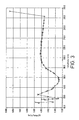
- the optimum pressure at which the stream of the liquid product is introduced into the main heat exchanger will depend on a number of different parameters. It is typically chosen so as to keep the maximum temperature difference (between streams being warmed and streams being cooled) at any section of the main heat exchanger where the air temperature is less than 160K to less than 5 degrees Kelvin, with the mean temperature difference being typically in the range of 2 to 3.5 degrees Kelvin, but to provide a minimum temperature difference between the air being cooled and the product streams being warmed in the main heat exchanger in the range of one to two degrees Kelvin (1-2 Kelvin). If too high a pressure or too large a flow is chosen, the temperature difference becomes too small e.g.
- the entire oxygen product is withdrawn from the lower pressure column in liquid state, at least a part of the entire liquid oxygen product is expanded through a valve, and the resulting expanded liquid oxygen stream is partially vaporised so as to form a liquid phase and a vapour phase.
- the vapour phase is taken as the said stream of oxygen product and the liquid phase is pressurised so as to form the said stream of liquid product of the rectification.
- a part of the entire liquid oxygen product bypasses the expansion valve and is raised to a desired pressure so as to form the stream of liquid product of the rectification, and the entire flow through the expansion valve is vaporised so as to form the said stream of oxygen product.
- the said stream of the liquid product of the rectification forms from 20-30 mole per cent of the entire oxygen product.
- the said stream of the liquid product of the rectification may comprise a condensed stream of a nitrogen fraction taken from the higher or lower pressure column.
- the rectification columns are preferably operated with higher reflux ratios than is conventional.
- additional liquid nitrogen reflux is preferably employed.
- the additional liquid nitrogen reflux may if desired be introduced from a source independent of the air separation plant.
- the method according to the invention utilises a further rectification column in which a stream of oxygen-enriched liquid separated in the higher pressure column is subjected to further separation so as to form an oxygen-containing fraction from which feed to the lower pressure column is taken and a nitrogen fraction, a flow of which nitrogen fraction is condensed, some of the resulting condensate being used as reflux in the lower pressure column and some being used as reflux in the further rectification column.
- the further rectification column is typically operated at a pressure at its top lower than the top pressure of the higher pressure column but higher than the top pressure of the lower pressure column. It is not essential that the nitrogen fraction at the top of the further rectification column be of the same purity as that of the lower pressure column or that of the higher pressure column.
- the condensation of the nitrogen fraction separated in the further rectification column is preferably performed by indirect heat exchange with a stream of the said oxygen-containing fraction separated in the further rectification column.
- the stream of oxygen-enriched liquid withdrawn from the higher pressure column for separation in the further rectification column is preferably reboiled upstream of or in the further rectification column by indirect heat exchange with a stream of nitrogen vapour withdrawn from a top region of the higher pressure column.
- a bottom liquid fraction separated in the further rectification column may be so reboiled.
- the method according to the invention is particularly suitable for use if most or all of the oxygen product is to be supplied to a high pressure partial oxidation process.
- the size of the partial oxidation unit and the proportion of the oxygen product that is sent to the unit tend to dictate the requirement for oxygen from the double rectification column.
- the plant according to the invention can meet its demand for oxygen product while typically supplying sufficient nitrogen to enable the requirements for control of oxides of nitrogen in a gas turbine to be met.
- the partial oxidation reaction typically employs impure oxygen having an oxygen content in the range of 80 to 98.5 mole per cent, typically 95 mole per cent.
- the double rectification column is preferably of a plural reboiler kind, in which in the lower pressure column a bottom impure liquid oxygen fraction is reboiled by indirect heat exchange with, preferably, at least part of the first flow of the compressed air to be separated, and in which an intermediate fraction is reboiled by indirect heat exchange with nitrogen separated in the higher pressure column.
- the vaporisation of the oxygen product is preferably effected by indirect heat exchange with a stream of the nitrogen separated in the higher pressure column.
- Refrigeration for the method according to the invention is preferably provided by taking a second flow of air from the first flow at a region intermediate the warm end and the cold end of the main heat exchanger and expanding it in an expansion turbine with the performance of external work.
- the resulting expanded air is preferably introduced into the double rectification column typically its lower pressure column.
- Rectification columns for use in the method according to the invention are typically each constituted by one or more vessels in which downflowing liquid is brought into intimate mass exchange relationship with ascending vapour. It is, however, within the scope of the invention to omit from the further rectification column any means for effecting such intimate mass exchange such that the further rectification column becomes a phase separator.
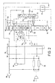
- Figures 1 and 2 are schematic flow diagrams of air separation plant for performing the method according to the invention
- Figure 3 is a graph showing the magnitude of the temperature difference between the streams being cooled and the streams being warmed in the main heat exchanger of the plant shown in Figure 1.
- a first flow of air is compressed in a first train 2 of a chosen number of compression stages 4, 6, 8, 10 and 12.
- Each of the compression stages 4, 6, 8, 10 and 12 has its own after-cooler (not shown) immediately downstream thereof in order to remove heat of compression from the air.
- Each after-cooler may take the form of an indirect heat exchanger, although it is sometimes preferred to'employ a direct contact water chiller as the after-cooler immediately downstream of the final stage 12.
- all five of the compression stages 4, 6, 8, 10 and 12 may be located in a single housing and form a single main compressor.
- the most downstream stage 12 or the downstream stages 10 and 12 may be located in a separate housing and form a separate compressor.
- the first fully compressed flow of air passes, typically at a temperature in the range of 2 to 20 degrees Celsius and typically at a pressure in the range of 8 to 14 bar absolute, to a purification unit 14 in which it is purified by adsorption.
- the purification unit 14 is arranged so as to purify not only the first flow of air but also a second flow of compressed air.
- the second flow of compressed air is taken from an air compressor 18 forming part of a gas turbine 16 including, in addition to the compressor 18, a combustion chamber 20 and a turbo-expander 22.
- the gas turbine 16 is arranged such that air from the compressor 18 and fuel gas (from a source described below) are sent to the combustion chamber 20 and the resulting combustion products are expanded with the performance of external work by the turbo-expander 22.
- the external work performed is typically the generation of electricity.
- the air compressor 18 includes a train of two or more compression stages 24 and 26. A bleed of air is withdrawn from the final or most downstream of the compression stages 24 and 26 and is cooled to ambient temperature or a temperature typically within the range of 2 to 20 degrees centigrade by passage through an after-cooler (not shown) typically in the form of a direct contact water chiller.
- the resulting chilled air flow forms a second flow of air that is sent to the purification unit 14.
- the purification unit 14 is shown only schematically in Figure 1 of the drawings, various valves and pipes having been omitted.
- the unit 14 includes three pressure vessels 28, 30 and 32, each housing a bed or beds of adsorbent for purifying the first and second flows of air.
- the arrangement is such that while one of the vessels 28, 30 and 32 is being used to purify the first flow of air, a second one is being used to purify the second flow of air, and a third or remaining one is being regenerated.
- the purification is effected by adsorption of impurities, particularly, water vapour, carbon dioxide and hydrocarbons having two or more carbon atoms from the incoming air.
- a bed of activated alumina, or an upstream bed of activated alumina and a downstream bed of 13X zeolite are employed for this purpose.
- Regeneration of one of the vessels, 28, 30, and 32 which is not on-line may be effected by subjecting the adsorbent therein to a pressure markedly lower than the adsorption pressure or a temperature markedly higher than the adsorption temperature.
- the former technique is known as pressure swing adsorption and the latter as temperature swing adsorption.
- the design of temperature swing adsorption and pressure swing adsorption processes for purification of air is well known in the art and the purification unit 14 shall not be described in further detail except in one respect.
- the adsorption unit 14 has two vessels on adsorption duty at any one time for each vessel that is off-line being regenerated (or having been regenerated).
- This arrangement is made possible because the second flow is at a substantially higher pressure than the first flow of air. Since the flows are approximately equal, and since each of the vessels 28, 30 and 32 contain the same amount of adsorbent, by the time that impurities are about to break through the adsorbent bed or beds in the chosen one of the vessels 28, 30 and 32 which receives the first flow of air, the adsorbent or adsorbents in the chosen one of these vessels in which the second flow of air is being purified still has available adsorption capacity.
- the thus purified first flow of air follows a flow path 34 which extends through a main heat exchanger 36 from its warm end 38 to its cold end 39.
- the air is thus cooled (by indirect heat exchange with returned streams) to a cryogenic temperature a little above that at which it is rectified.
- the resulting cooled first flow of compressed air is separated in an arrangement of a double rectification column 40 and a further rectification column 42.
- the double rectification column 40 includes a higher pressure column 44 and a lower pressure column 46.
- the lower pressure column 46 is provided with a first reboiler-condenser 48 in a bottom region 50 thereof and a second reboiler-condenser 51 in an intermediate region 54 thereof.
- the further rectification column 42 is provided with a further reboiler-condenser 56 in a bottom region 58 thereof and a condenser 60 in a top region 63 thereof.
- the first flow of cooled air passes from the cold end 39 of the main heat exchanger 36 through the first reboiler-condenser 48 associated with the lower pressure column 46.
- the purified second flow of compressed air flows through the main heat exchanger 36 from its warm end 38 to its cold end 39 and is thereby cooled to a cryogenic temperature.
- the resulting cooled second purified flow of compressed air is expanded in an expansion turbine 41 with the performance of external work.
- the thus expanded second purified flow of air is exhausted from the expansion turbine at essentially the same pressure as that at which the first purified flow of compressed air leaves the cold end 39 of the main heat exchanger 36.
- the combined flows of air are partially condensed by indirect heat exchange with the bottom liquid fraction that is separated in the lower pressure column 46.
- Reboil that is an upward flow of vapour, is thereby created in the lower pressure column 46.
- the partially condensed flow of air passes out of the first reboiler-condenser 48 and is introduced through an inlet 62 into a bottom region of the higher pressure column 44.
- a minor part of the second flow of compressed air is withdrawn from an intermediate region of the main heat exchanger 36, is passed through an expansion valve 43 so as to reduce its pressure to essentially the operating pressure of the higher pressure column 44 and is introduced into the column 44 in essentially liquid state through an inlet 45 at an intermediate level thereof. Less than 5% of the total air flow is liquefied.
- Nitrogen vapour is separated in the higher pressure column 44 from the air introduced through the inlets 62 and 45. The nitrogen collects at the top of the higher pressure column 44.
- An oxygen-enriched liquid fraction collects at the bottom of the higher pressure column 44
- a stream of the oxygen-enriched liquid air fraction is withdrawn from the bottom of the higher pressure column 44 through an outlet 64, is sub-cooled by passage through a further heat exchanger 66 and is expanded, that is reduced in pressure, by passage through a Joule-Thomson or throttling valve 68.
- the resulting expanded stream of oxygen-enriched liquid air is introduced into an intermediate region of the further rectification column 42 for separation therein.
- the nitrogen vapour fraction obtained at the top of the higher pressure column 44 is condensed. As will be described below, a part of the nitrogen condensate is returned to the higher pressure column 44 as reflux.
- the remainder although for ease of illustration not shown in Figure 1 of the drawings, is preferably sub-cooled by passage through the further heat exchanger 66, is expanded by passage through a Joule-Thomson or throttling valve 72 and is introduced into the top of the lower pressure column 46 through an inlet 74 as a reflux stream.
- the oxygen-enriched liquid air stream introduced into the further rectification column 42 is separated therein into a bottom oxygen-enriched liquid air fraction, usually containing a greater mole fraction of oxygen than the feed to the column 42, and a top nitrogen fraction, typically, but not necessarily, impure.
- An upward flow of vapour in the further rectification column 42 is formed by reboiling of the bottom liquid fraction in the reboiler-condenser 56.
- the necessary heating of the recoiler-condenser 56 is effected by a stream of the top nitrogen fraction formed in the higher pressure column 44.
- the stream of nitrogen is condensed and is returned to the higher pressure column 44 as reflux.
- a part of the reflux requirements of the lower pressure column 46 may also be met from this stream of condensed nitrogen.
- Reflux for the further rectification column 42 is formed by withdrawing a stream of the bottom oxygen-enriched liquid fraction from the bottom region of this column, expanding it through a Joule-Thomson or throttling valve 76 and condensing it in the condenser 60 by indirect heat exchange with a flow of the top nitrogen fraction that is obtained in the further rectification column 42.
- a part of the resulting condensate is expanded through a Joule-Thomson or throttling valve 78 and is introduced into an upper region of the lower pressure column 46 through an inlet 80 so as to augment the reflux in all but the uppermost region of the column 46.
- this stream of condensate may be sub-cooled by passage through the further heat exchanger 66. The remainder of the condensate serves as reflux for the further rectification column 42.
- the oxygen-enriched liquid stream is typically totally vaporised in the condenser 60 and is introduced through an inlet 82 into the lower pressure column 46 as a feed stream to be separated therein.
- the feed stream is separated into an impure liquid oxygen fraction, typically containing 95% by volume of oxygen, which collects at the bottom of the lower pressure column 46 and a top nitrogen fraction typically containing less than 0.5% by volume of oxygen impurity, which top fraction collects at the top of the lower pressure column 46.
- passage of the first flow of air through the reboiler-condenser 48 creates an upward vapour flow in the lower pressure column 46.
- the vapour flow in the upper regions of the lower pressure column 46 is augmented by operation of the second reboiler-condenser 52.
- the reboiler-condenser 52 is heated by means of a further stream of the nitrogen that is separated in the higher pressure column 44.
- the nitrogen is condensed and the resulting condensate is used as reflux in the lower pressure column 46.
- the condensation of the nitrogen in the second reboiler-condenser 52 is incomplete and uncondensed vapour passes into a product oxygen vaporiser 84 in which it is condensed by indirect heat exchange, as described below, with vaporising oxygen product.
- An impure oxygen product is withdrawn through an outlet 86 from the bottom region 50 of the lower pressure column 46.
- the impure liquid oxygen product stream flows through a throttling or Joule-Thomson valve 88 into the vaporiser 84 in which it is vaporised, as aforesaid, by heat exchange with a stream of nitrogen vapour passing out of the second reboiler-condenser 52.
- the nitrogen is condensed and may, as shown in Figure 1, be combined with the nitrogen which is condensed in the second reboiler-condenser 52.
- An alternative to the illustrated arrangement is to send the nitrogen vapour to the vaporiser 84 directly and not via the second reboiler-condenser 52.
- the impure liquid oxygen product is not totally vaporised in the vaporiser 84, about 20% of it remaining in the liquid state.
- the resulting oxygen vapour is returned through the main heat exchanger 36 from its cold end 40 to its warm end 39 and is compressed to a pressure of, say, 80 bar in an oxygen-compressor 90.
- the resulting compressed oxygen is supplied to a partial oxidation unit 92.
- a fuel such as coal is also supplied to the partial oxidation unit 92.
- Fuel gas is formed in the partial oxidation unit 92.
- a stream of fuel gas is taken therefrom, is purified (by means not shown) and is sent to the combustion chamber 20 of the gas turbine 16 for combustion therein so as to form the hot combustion gases that are expanded by the turbo-expander 22.
- a stream of the residual liquid oxygen product is withdrawn from the vaporiser 84 and is pressurised by a liquid oxygen pump 94 to a pressure typically in the order of 40 bar.
- the resulting pressurised oxygen stream is passed through the main heat exchanger 36 from its cold end 39 to its warm end 38. Typically, it is combined with the compressed oxygen product in or downstream of the oxygen compressor 90.
- the pressure to which the liquid oxygen stream is raised by the pump 94 is typically in the range 20 to 60 bar (absolute). This stream has the effect of keeping down the temperature difference between streams being warmed and streams being cooled in the main heat exchanger 36, particularly in the region thereof where the temperature of the stream 34 is less than 160K.
- a stream of nitrogen product is withdrawn from the lower pressure column 46 through an outlet 96 thereof and flows through the heat exchanger 66 thereby providing refrigeration for the sub-cooling that is effected therein.
- the flow of the nitrogen product continues through the main heat exchanger 36 from its cold end 39 to its warm end 38.
- a part of the resulting nitrogen stream is taken for bed regeneration purposes in the purification unit 14.
- the remainder of the nitrogen stream is compressed in a nitrogen compressor 98 to the operating pressure of the combustion chamber 20 of the gas turbine 16 and is introduced into the combustion chamber 20 or the turbo-expander 22 so as to reduce NOx formation during operation of the gas turbine 16.
- Moist nitrogen may be returned to the nitrogen product from the purification unit.
- FIG. 2 of the drawings illustrates a method according to the invention in which just one main air compressor is employed. Referring to Figure 2, a flow of air is compressed to a pressure in the range of 8.5 to 16 bar in a main air compressor 102. Heat of compression is removed from the air leaving the main air compressor 102 and the resulting cooled, compressed, air is purified by adsorption of low volatility impurities such as water vapour and carbon dioxide in a purification unit 104.
- the resulting purified air flows through a main heat exchanger 106 from its warm end 108 to its cold end 110.
- the thus cooled compressed air flows through a first reboiler-condenser 112 and is partially condensed therein.
- the resulting partially condensed air stream is introduced into a bottom region of a higher pressure column 114 forming a double rectification column 120 with a lower pressure column 116 and a second condenser-reboiler 118.
- the air introduced into the higher pressure column 114 is separated into an oxygen-enriched liquid air fraction at the bottom thereof and a nitrogen vapour fraction at the top thereof.
- a stream of the oxygen-enriched liquid air fraction is withdrawn from the bottom of the higher pressure column 114 through an outlet 122, is sub-cooled by passage through a further heat exchanger 124 and is expanded, that is reduced in pressure, by passage through a Joule-Thomson or throttling valve 126.
- the resulting expanded stream of oxygen-enriched liquid air is introduced into an intermediate region of a further rectification column 128 for separation therein.
- a part of the nitrogen vapour fraction obtained at the top of the higher pressure column 114 is condensed in the condenser-reboiler 118.
- a part of the nitrogen condensate is returned to the higher pressure column as reflux.
- the remainder although for ease of illustration not shown in the drawing, is preferably sub-cooled by passage through the further heat exchanger 124, is expanded by passage through a Joule-Thomson or throttling valve 130, and is introduced into the top of the lower pressure column 118 through an inlet 131 as a reflux stream.
- the oxygen-enriched liquid air stream introduced into the further rectification column 128 is separated therein a bottom oxygen-enriched liquid air fraction, usually containing a greater mole fraction of oxygen than the feed to the column 128, and a top nitrogen fraction, typically but not necessarily, impure.
- An upward flow of vapour in the further rectification column 128 is formed by reboiling of the bottom liquid fraction in a condenser-reboiler 132.
- the necessary heating of the condenser-reboiler 132 is effected by a stream of another part of the top nitrogen fraction formed in the higher pressure column 114.
- the stream of nitrogen is thereby condensed and is returned to the higher pressure column 114 as reflux.
- Reflux for the further rectification column 128 is formed by withdrawing a stream of the bottom oxygen-enriched liquid fraction from the bottom of this column, expanding it through a Joule-Thomson or throttling valve 134 and condensing it in a head condenser 136 by indirect heat exchange with a flow of the top nitrogen fraction that is obtained in the further rectification column 128.
- a part of the resulting condensate is expanded through a Joule-Thomson or throttling valve 138 and is introduced into an upper region of the lower pressure column 116 through an inlet 140 so as to augment the reflux in all but the uppermost region of the lower pressure column 116. If desired, this stream of condensate may be sub-cooled by passage through the further heat exchanger 124. The remainder of the condensate serves as reflux for the further rectification column 128.
- the oxygen-enriched liquid stream is typically totally vaporised in the head condenser 136 and is introduced through an inlet 142 into the lower pressure column 116 as a feed stream to be separated therein.
- Another feed stream to the lower pressure column 116 is formed by withdrawing a stream of air from the compressed purified air flowing through the main heat exchanger 106 and expanding it with the performance of external work in an expansion turbine 144.
- the resulting expanded air leaves the expansion turbine 144 at a temperature and pressure suitable for its rectification in the lower pressure column 116 and is introduced into an intermediate region of the column 116 through an inlet 146.
- the air streams are separated by rectification in the lower pressure column 116 into an impure liquid oxygen fraction, typically containing 95% by volume of oxygen which collects at the bottom of the lower pressure column 116, and a top nitrogen fraction typically containing less than 0.5% by volume of oxygen impurity, which top fraction collects at the top of the lower pressure column 116.
- Passage of the air through the first reboiler-condenser 112 creates an upward vapour flow in the lower pressure column 116.
- the vapour flow in the upper regions of the lower pressure column 116 is augmented by operation of the second reboiler-condenser 118.
- the reboiler-condenser 118 is heated by means of a further stream of the nitrogen separated in the higher pressure column 114.
- the nitrogen is condensed and the resulting condensate is used as reflux in the lower pressure column 116.
- the condensation of the nitrogen in the second reboiler-condenser 118 is incomplete and uncondensed vapour passes into a product oxygen vaporiser 148 in which it is condensed, as described below, by indirect heat exchange with vaporising oxygen product.
- An impure oxygen product is withdrawn through an outlet 150 from the bottom region of the lower pressure column 116.
- the impure liquid oxygen product stream flows through a throttling or Joule-Thomson valve 152 (which reduces its pressure) into the vaporiser 148 in which it is vaporised, as aforesaid, by heat exchange with a stream of nitrogen vapour passing out of the second reboiler-condenser 116.
- the nitrogen is condensed and may, as shown in Figure 2, be combined with the nitrogen which is condensed in the second reboiler-condenser 118.
- An alternative to the illustrated arrangement is to send the nitrogen vapour to the vaporiser 148 directly and not via the second reboiler-condenser 118.
- the impure liquid oxygen product is not totally vaporised in the vaporiser 148, about 20% of it remaining in the liquid state.
- the resulting oxygen vapour is returned through the main heat exchanger 106 from its cold end 110 to its warm end 108 and is compressed to a pressure of, say, 80 bar in an oxygen compressor 154.
- the resulting compressed oxygen is supplied to a partial oxidation unit (not shown).
- a stream of the residual liquid oxygen product is withdrawn from the vaporiser 144 and is pressurised by a liquid oxygen pump 156 to a pressure typically in the order of 35 to 40 bar (a).
- the resulting pressurised oxygen stream is passed through the main heat exchanger 106 from its cold end 110 to its warm end 108. Typically, it is combined with the vaporous oxygen system in the oxygen compressor 154.
- the pressurised liquid oxygen stream in accordance with the invention, performs the function of reducing the temperature difference between streams being warmed and streams being cooled in lower temperature regions of the main heat exchanger 106 (i.e. those regions where the temperature of the air being cooled is less than 160K).
- a stream of nitrogen product is withdrawn from the lower pressure column 116 through an outlet 158 at the top thereof and flows through the further heat exchanger 124 thereby providing refrigeration for the sub-cooling that is effected therein.
- the flow of the nitrogen product continues through the main heat exchanger 106 from its cold end 110 to its warm end 108.
- the nitrogen may be further compressed in a compressor 160 and used to suppress NO x emissions from a gas turbine (not shown). If desired a part of the nitrogen product may be used to purge impurities from the purification unit 104 with resulting moist nitrogen returned to the nitrogen product stream upstream of the compressor 160.
- the higher pressure column 114 has an operating pressure of 160 psia (10.9 bar) at its bottom; the lower pressure column 116 has an operating pressure of 72 psia (4.9 bar) at its top; the further rectification column 128 has an operating pressure of 111 psia (7.5 bar) at its top, and the oxygen vaporiser has an operating pressure of 3.8 bar on its oxygen side. None of the air is liquefied upstream of the double rectification column 120 in this example.
- the pump 156 raises the pressure of the liquid oxygen to 35 bar.
Applications Claiming Priority (2)
| Application Number | Priority Date | Filing Date | Title |
|---|---|---|---|
| GB0002084 | 2000-01-28 | ||
| GB0002084A GB0002084D0 (en) | 2000-01-28 | 2000-01-28 | Air separation method |
Publications (2)
| Publication Number | Publication Date |
|---|---|
| EP1120616A2 true EP1120616A2 (fr) | 2001-08-01 |
| EP1120616A3 EP1120616A3 (fr) | 2002-08-28 |
Family
ID=9884599
Family Applications (1)
| Application Number | Title | Priority Date | Filing Date |
|---|---|---|---|
| EP01300189A Withdrawn EP1120616A3 (fr) | 2000-01-28 | 2001-01-10 | Méthode de séparation de l'air |
Country Status (2)
| Country | Link |
|---|---|
| EP (1) | EP1120616A3 (fr) |
| GB (1) | GB0002084D0 (fr) |
Cited By (1)
| Publication number | Priority date | Publication date | Assignee | Title |
|---|---|---|---|---|
| CN102155841A (zh) * | 2010-02-11 | 2011-08-17 | 普莱克斯技术有限公司 | 低温分离方法及设备 |
Citations (7)
| Publication number | Priority date | Publication date | Assignee | Title |
|---|---|---|---|---|
| EP0562893A1 (fr) * | 1992-03-24 | 1993-09-29 | L'air Liquide, Societe Anonyme Pour L'etude Et L'exploitation Des Procedes Georges Claude | Procédé et installation de production d'azote sous haute pression et d'oxygène |
| EP0633438A1 (fr) * | 1993-07-05 | 1995-01-11 | The BOC Group plc | Séparation de l'air |
| EP0717249A2 (fr) * | 1994-12-16 | 1996-06-19 | The BOC Group plc | Séparation d'air |
| EP0793070A2 (fr) * | 1996-01-31 | 1997-09-03 | Air Products And Chemicals, Inc. | Intégration d'une turbine à combustion à haute température et d'un système de séparation d'air |
| US5692395A (en) * | 1995-01-20 | 1997-12-02 | Agrawal; Rakesh | Separation of fluid mixtures in multiple distillation columns |
| EP0949471A1 (fr) * | 1998-04-08 | 1999-10-13 | Linde Aktiengesellschaft | Unité de séparation de l'air à deux modes de fonctionnement |
| EP1199532A1 (fr) * | 2000-10-20 | 2002-04-24 | Linde Aktiengesellschaft | Système de séparation d'air cryogénique à trois colonnes |
-
2000
- 2000-01-28 GB GB0002084A patent/GB0002084D0/en not_active Ceased
-
2001
- 2001-01-10 EP EP01300189A patent/EP1120616A3/fr not_active Withdrawn
Patent Citations (7)
| Publication number | Priority date | Publication date | Assignee | Title |
|---|---|---|---|---|
| EP0562893A1 (fr) * | 1992-03-24 | 1993-09-29 | L'air Liquide, Societe Anonyme Pour L'etude Et L'exploitation Des Procedes Georges Claude | Procédé et installation de production d'azote sous haute pression et d'oxygène |
| EP0633438A1 (fr) * | 1993-07-05 | 1995-01-11 | The BOC Group plc | Séparation de l'air |
| EP0717249A2 (fr) * | 1994-12-16 | 1996-06-19 | The BOC Group plc | Séparation d'air |
| US5692395A (en) * | 1995-01-20 | 1997-12-02 | Agrawal; Rakesh | Separation of fluid mixtures in multiple distillation columns |
| EP0793070A2 (fr) * | 1996-01-31 | 1997-09-03 | Air Products And Chemicals, Inc. | Intégration d'une turbine à combustion à haute température et d'un système de séparation d'air |
| EP0949471A1 (fr) * | 1998-04-08 | 1999-10-13 | Linde Aktiengesellschaft | Unité de séparation de l'air à deux modes de fonctionnement |
| EP1199532A1 (fr) * | 2000-10-20 | 2002-04-24 | Linde Aktiengesellschaft | Système de séparation d'air cryogénique à trois colonnes |
Cited By (1)
| Publication number | Priority date | Publication date | Assignee | Title |
|---|---|---|---|---|
| CN102155841A (zh) * | 2010-02-11 | 2011-08-17 | 普莱克斯技术有限公司 | 低温分离方法及设备 |
Also Published As
| Publication number | Publication date |
|---|---|
| GB0002084D0 (en) | 2000-03-22 |
| EP1120616A3 (fr) | 2002-08-28 |
Similar Documents
| Publication | Publication Date | Title |
|---|---|---|
| US20200149806A1 (en) | System and method for enhanced recovery of argon and oxygen from a nitrogen producing cryogenic air separation unit | |
| EP0454327B2 (fr) | Séparation d'air | |
| US10969168B2 (en) | System and method for enhanced recovery of argon and oxygen from a nitrogen producing cryogenic air separation unit | |
| US5546766A (en) | Air separation | |
| CA3097179C (fr) | Systeme et procede de recuperation assistee d'argon et d'oxygene a partir d'une unite de separation d'air cryogenique de production d'azote | |
| US10981103B2 (en) | System and method for enhanced recovery of liquid oxygen from a nitrogen and argon producing cryogenic air separation unit | |
| US5309721A (en) | Air separation | |
| US6305191B1 (en) | Separation of air | |
| EP1030148B1 (fr) | Séparation des gaz de l'air | |
| US6170291B1 (en) | Separation of air | |
| EP1120616A2 (fr) | Méthode de séparation de l'air | |
| EP1120617A2 (fr) | Séparation de l'air | |
| EP0831284B1 (fr) | Séparation d'air | |
| US11933538B2 (en) | System and method for recovery of nitrogen, argon, and oxygen in moderate pressure cryogenic air separation unit | |
| GB2266363A (en) | Air separation |
Legal Events
| Date | Code | Title | Description |
|---|---|---|---|
| PUAI | Public reference made under article 153(3) epc to a published international application that has entered the european phase |
Free format text: ORIGINAL CODE: 0009012 |
|
| AK | Designated contracting states |
Kind code of ref document: A2 Designated state(s): AT BE CH CY DE DK ES FI FR GB GR IE IT LI LU MC NL PT SE TR |
|
| AX | Request for extension of the european patent |
Free format text: AL;LT;LV;MK;RO;SI |
|
| PUAL | Search report despatched |
Free format text: ORIGINAL CODE: 0009013 |
|
| AK | Designated contracting states |
Kind code of ref document: A3 Designated state(s): AT BE CH CY DE DK ES FI FR GB GR IE IT LI LU MC NL PT SE TR |
|
| AX | Request for extension of the european patent |
Free format text: AL;LT;LV;MK;RO;SI |
|
| AKX | Designation fees paid | ||
| REG | Reference to a national code |
Ref country code: DE Ref legal event code: 8566 |
|
| STAA | Information on the status of an ep patent application or granted ep patent |
Free format text: STATUS: THE APPLICATION IS DEEMED TO BE WITHDRAWN |
|
| 18D | Application deemed to be withdrawn |
Effective date: 20030301 |