EP1120617A2 - Séparation de l'air - Google Patents
Séparation de l'air Download PDFInfo
- Publication number
- EP1120617A2 EP1120617A2 EP01300191A EP01300191A EP1120617A2 EP 1120617 A2 EP1120617 A2 EP 1120617A2 EP 01300191 A EP01300191 A EP 01300191A EP 01300191 A EP01300191 A EP 01300191A EP 1120617 A2 EP1120617 A2 EP 1120617A2
- Authority
- EP
- European Patent Office
- Prior art keywords
- air
- pressure column
- column
- oxygen
- higher pressure
- Prior art date
- Legal status (The legal status is an assumption and is not a legal conclusion. Google has not performed a legal analysis and makes no representation as to the accuracy of the status listed.)
- Withdrawn
Links
Images
Classifications
-
- F—MECHANICAL ENGINEERING; LIGHTING; HEATING; WEAPONS; BLASTING
- F25—REFRIGERATION OR COOLING; COMBINED HEATING AND REFRIGERATION SYSTEMS; HEAT PUMP SYSTEMS; MANUFACTURE OR STORAGE OF ICE; LIQUEFACTION SOLIDIFICATION OF GASES
- F25J—LIQUEFACTION, SOLIDIFICATION OR SEPARATION OF GASES OR GASEOUS OR LIQUEFIED GASEOUS MIXTURES BY PRESSURE AND COLD TREATMENT OR BY BRINGING THEM INTO THE SUPERCRITICAL STATE
- F25J3/00—Processes or apparatus for separating the constituents of gaseous or liquefied gaseous mixtures involving the use of liquefaction or solidification
- F25J3/02—Processes or apparatus for separating the constituents of gaseous or liquefied gaseous mixtures involving the use of liquefaction or solidification by rectification, i.e. by continuous interchange of heat and material between a vapour stream and a liquid stream
- F25J3/04—Processes or apparatus for separating the constituents of gaseous or liquefied gaseous mixtures involving the use of liquefaction or solidification by rectification, i.e. by continuous interchange of heat and material between a vapour stream and a liquid stream for air
- F25J3/04151—Purification and (pre-)cooling of the feed air; recuperative heat-exchange with product streams
- F25J3/04163—Hot end purification of the feed air
- F25J3/04169—Hot end purification of the feed air by adsorption of the impurities
- F25J3/04175—Hot end purification of the feed air by adsorption of the impurities at a pressure of substantially more than the highest pressure column
-
- F—MECHANICAL ENGINEERING; LIGHTING; HEATING; WEAPONS; BLASTING
- F25—REFRIGERATION OR COOLING; COMBINED HEATING AND REFRIGERATION SYSTEMS; HEAT PUMP SYSTEMS; MANUFACTURE OR STORAGE OF ICE; LIQUEFACTION SOLIDIFICATION OF GASES
- F25J—LIQUEFACTION, SOLIDIFICATION OR SEPARATION OF GASES OR GASEOUS OR LIQUEFIED GASEOUS MIXTURES BY PRESSURE AND COLD TREATMENT OR BY BRINGING THEM INTO THE SUPERCRITICAL STATE
- F25J3/00—Processes or apparatus for separating the constituents of gaseous or liquefied gaseous mixtures involving the use of liquefaction or solidification
- F25J3/02—Processes or apparatus for separating the constituents of gaseous or liquefied gaseous mixtures involving the use of liquefaction or solidification by rectification, i.e. by continuous interchange of heat and material between a vapour stream and a liquid stream
- F25J3/04—Processes or apparatus for separating the constituents of gaseous or liquefied gaseous mixtures involving the use of liquefaction or solidification by rectification, i.e. by continuous interchange of heat and material between a vapour stream and a liquid stream for air
- F25J3/04006—Providing pressurised feed air or process streams within or from the air fractionation unit
- F25J3/04012—Providing pressurised feed air or process streams within or from the air fractionation unit by compression of warm gaseous streams; details of intake or interstage cooling
- F25J3/04036—Providing pressurised feed air or process streams within or from the air fractionation unit by compression of warm gaseous streams; details of intake or interstage cooling of oxygen
-
- F—MECHANICAL ENGINEERING; LIGHTING; HEATING; WEAPONS; BLASTING
- F25—REFRIGERATION OR COOLING; COMBINED HEATING AND REFRIGERATION SYSTEMS; HEAT PUMP SYSTEMS; MANUFACTURE OR STORAGE OF ICE; LIQUEFACTION SOLIDIFICATION OF GASES
- F25J—LIQUEFACTION, SOLIDIFICATION OR SEPARATION OF GASES OR GASEOUS OR LIQUEFIED GASEOUS MIXTURES BY PRESSURE AND COLD TREATMENT OR BY BRINGING THEM INTO THE SUPERCRITICAL STATE
- F25J3/00—Processes or apparatus for separating the constituents of gaseous or liquefied gaseous mixtures involving the use of liquefaction or solidification
- F25J3/02—Processes or apparatus for separating the constituents of gaseous or liquefied gaseous mixtures involving the use of liquefaction or solidification by rectification, i.e. by continuous interchange of heat and material between a vapour stream and a liquid stream
- F25J3/04—Processes or apparatus for separating the constituents of gaseous or liquefied gaseous mixtures involving the use of liquefaction or solidification by rectification, i.e. by continuous interchange of heat and material between a vapour stream and a liquid stream for air
- F25J3/04006—Providing pressurised feed air or process streams within or from the air fractionation unit
- F25J3/04078—Providing pressurised feed air or process streams within or from the air fractionation unit providing pressurized products by liquid compression and vaporisation with cold recovery, i.e. so-called internal compression
- F25J3/0409—Providing pressurised feed air or process streams within or from the air fractionation unit providing pressurized products by liquid compression and vaporisation with cold recovery, i.e. so-called internal compression of oxygen
-
- F—MECHANICAL ENGINEERING; LIGHTING; HEATING; WEAPONS; BLASTING
- F25—REFRIGERATION OR COOLING; COMBINED HEATING AND REFRIGERATION SYSTEMS; HEAT PUMP SYSTEMS; MANUFACTURE OR STORAGE OF ICE; LIQUEFACTION SOLIDIFICATION OF GASES
- F25J—LIQUEFACTION, SOLIDIFICATION OR SEPARATION OF GASES OR GASEOUS OR LIQUEFIED GASEOUS MIXTURES BY PRESSURE AND COLD TREATMENT OR BY BRINGING THEM INTO THE SUPERCRITICAL STATE
- F25J3/00—Processes or apparatus for separating the constituents of gaseous or liquefied gaseous mixtures involving the use of liquefaction or solidification
- F25J3/02—Processes or apparatus for separating the constituents of gaseous or liquefied gaseous mixtures involving the use of liquefaction or solidification by rectification, i.e. by continuous interchange of heat and material between a vapour stream and a liquid stream
- F25J3/04—Processes or apparatus for separating the constituents of gaseous or liquefied gaseous mixtures involving the use of liquefaction or solidification by rectification, i.e. by continuous interchange of heat and material between a vapour stream and a liquid stream for air
- F25J3/04151—Purification and (pre-)cooling of the feed air; recuperative heat-exchange with product streams
- F25J3/04163—Hot end purification of the feed air
- F25J3/04169—Hot end purification of the feed air by adsorption of the impurities
-
- F—MECHANICAL ENGINEERING; LIGHTING; HEATING; WEAPONS; BLASTING
- F25—REFRIGERATION OR COOLING; COMBINED HEATING AND REFRIGERATION SYSTEMS; HEAT PUMP SYSTEMS; MANUFACTURE OR STORAGE OF ICE; LIQUEFACTION SOLIDIFICATION OF GASES
- F25J—LIQUEFACTION, SOLIDIFICATION OR SEPARATION OF GASES OR GASEOUS OR LIQUEFIED GASEOUS MIXTURES BY PRESSURE AND COLD TREATMENT OR BY BRINGING THEM INTO THE SUPERCRITICAL STATE
- F25J3/00—Processes or apparatus for separating the constituents of gaseous or liquefied gaseous mixtures involving the use of liquefaction or solidification
- F25J3/02—Processes or apparatus for separating the constituents of gaseous or liquefied gaseous mixtures involving the use of liquefaction or solidification by rectification, i.e. by continuous interchange of heat and material between a vapour stream and a liquid stream
- F25J3/04—Processes or apparatus for separating the constituents of gaseous or liquefied gaseous mixtures involving the use of liquefaction or solidification by rectification, i.e. by continuous interchange of heat and material between a vapour stream and a liquid stream for air
- F25J3/04151—Purification and (pre-)cooling of the feed air; recuperative heat-exchange with product streams
- F25J3/04187—Cooling of the purified feed air by recuperative heat-exchange; Heat-exchange with product streams
- F25J3/04193—Division of the main heat exchange line in consecutive sections having different functions
- F25J3/04206—Division of the main heat exchange line in consecutive sections having different functions including a so-called "auxiliary vaporiser" for vaporising and producing a gaseous product
- F25J3/04212—Division of the main heat exchange line in consecutive sections having different functions including a so-called "auxiliary vaporiser" for vaporising and producing a gaseous product and simultaneously condensing vapor from a column serving as reflux within the or another column
-
- F—MECHANICAL ENGINEERING; LIGHTING; HEATING; WEAPONS; BLASTING
- F25—REFRIGERATION OR COOLING; COMBINED HEATING AND REFRIGERATION SYSTEMS; HEAT PUMP SYSTEMS; MANUFACTURE OR STORAGE OF ICE; LIQUEFACTION SOLIDIFICATION OF GASES
- F25J—LIQUEFACTION, SOLIDIFICATION OR SEPARATION OF GASES OR GASEOUS OR LIQUEFIED GASEOUS MIXTURES BY PRESSURE AND COLD TREATMENT OR BY BRINGING THEM INTO THE SUPERCRITICAL STATE
- F25J3/00—Processes or apparatus for separating the constituents of gaseous or liquefied gaseous mixtures involving the use of liquefaction or solidification
- F25J3/02—Processes or apparatus for separating the constituents of gaseous or liquefied gaseous mixtures involving the use of liquefaction or solidification by rectification, i.e. by continuous interchange of heat and material between a vapour stream and a liquid stream
- F25J3/04—Processes or apparatus for separating the constituents of gaseous or liquefied gaseous mixtures involving the use of liquefaction or solidification by rectification, i.e. by continuous interchange of heat and material between a vapour stream and a liquid stream for air
- F25J3/04248—Generation of cold for compensating heat leaks or liquid production, e.g. by Joule-Thompson expansion
- F25J3/04284—Generation of cold for compensating heat leaks or liquid production, e.g. by Joule-Thompson expansion using internal refrigeration by open-loop gas work expansion, e.g. of intermediate or oxygen enriched (waste-)streams
- F25J3/0429—Generation of cold for compensating heat leaks or liquid production, e.g. by Joule-Thompson expansion using internal refrigeration by open-loop gas work expansion, e.g. of intermediate or oxygen enriched (waste-)streams of feed air, e.g. used as waste or product air or expanded into an auxiliary column
- F25J3/04296—Claude expansion, i.e. expanded into the main or high pressure column
-
- F—MECHANICAL ENGINEERING; LIGHTING; HEATING; WEAPONS; BLASTING
- F25—REFRIGERATION OR COOLING; COMBINED HEATING AND REFRIGERATION SYSTEMS; HEAT PUMP SYSTEMS; MANUFACTURE OR STORAGE OF ICE; LIQUEFACTION SOLIDIFICATION OF GASES
- F25J—LIQUEFACTION, SOLIDIFICATION OR SEPARATION OF GASES OR GASEOUS OR LIQUEFIED GASEOUS MIXTURES BY PRESSURE AND COLD TREATMENT OR BY BRINGING THEM INTO THE SUPERCRITICAL STATE
- F25J3/00—Processes or apparatus for separating the constituents of gaseous or liquefied gaseous mixtures involving the use of liquefaction or solidification
- F25J3/02—Processes or apparatus for separating the constituents of gaseous or liquefied gaseous mixtures involving the use of liquefaction or solidification by rectification, i.e. by continuous interchange of heat and material between a vapour stream and a liquid stream
- F25J3/04—Processes or apparatus for separating the constituents of gaseous or liquefied gaseous mixtures involving the use of liquefaction or solidification by rectification, i.e. by continuous interchange of heat and material between a vapour stream and a liquid stream for air
- F25J3/04436—Processes or apparatus for separating the constituents of gaseous or liquefied gaseous mixtures involving the use of liquefaction or solidification by rectification, i.e. by continuous interchange of heat and material between a vapour stream and a liquid stream for air using at least a triple pressure main column system
- F25J3/04448—Processes or apparatus for separating the constituents of gaseous or liquefied gaseous mixtures involving the use of liquefaction or solidification by rectification, i.e. by continuous interchange of heat and material between a vapour stream and a liquid stream for air using at least a triple pressure main column system in a double column flowsheet with an intermediate pressure column
-
- F—MECHANICAL ENGINEERING; LIGHTING; HEATING; WEAPONS; BLASTING
- F25—REFRIGERATION OR COOLING; COMBINED HEATING AND REFRIGERATION SYSTEMS; HEAT PUMP SYSTEMS; MANUFACTURE OR STORAGE OF ICE; LIQUEFACTION SOLIDIFICATION OF GASES
- F25J—LIQUEFACTION, SOLIDIFICATION OR SEPARATION OF GASES OR GASEOUS OR LIQUEFIED GASEOUS MIXTURES BY PRESSURE AND COLD TREATMENT OR BY BRINGING THEM INTO THE SUPERCRITICAL STATE
- F25J3/00—Processes or apparatus for separating the constituents of gaseous or liquefied gaseous mixtures involving the use of liquefaction or solidification
- F25J3/02—Processes or apparatus for separating the constituents of gaseous or liquefied gaseous mixtures involving the use of liquefaction or solidification by rectification, i.e. by continuous interchange of heat and material between a vapour stream and a liquid stream
- F25J3/04—Processes or apparatus for separating the constituents of gaseous or liquefied gaseous mixtures involving the use of liquefaction or solidification by rectification, i.e. by continuous interchange of heat and material between a vapour stream and a liquid stream for air
- F25J3/04521—Coupling of the air fractionation unit to an air gas-consuming unit, so-called integrated processes
- F25J3/04527—Integration with an oxygen consuming unit, e.g. glass facility, waste incineration or oxygen based processes in general
- F25J3/04539—Integration with an oxygen consuming unit, e.g. glass facility, waste incineration or oxygen based processes in general for the H2/CO synthesis by partial oxidation or oxygen consuming reforming processes of fuels
- F25J3/04545—Integration with an oxygen consuming unit, e.g. glass facility, waste incineration or oxygen based processes in general for the H2/CO synthesis by partial oxidation or oxygen consuming reforming processes of fuels for the gasification of solid or heavy liquid fuels, e.g. integrated gasification combined cycle [IGCC]
-
- F—MECHANICAL ENGINEERING; LIGHTING; HEATING; WEAPONS; BLASTING
- F25—REFRIGERATION OR COOLING; COMBINED HEATING AND REFRIGERATION SYSTEMS; HEAT PUMP SYSTEMS; MANUFACTURE OR STORAGE OF ICE; LIQUEFACTION SOLIDIFICATION OF GASES
- F25J—LIQUEFACTION, SOLIDIFICATION OR SEPARATION OF GASES OR GASEOUS OR LIQUEFIED GASEOUS MIXTURES BY PRESSURE AND COLD TREATMENT OR BY BRINGING THEM INTO THE SUPERCRITICAL STATE
- F25J3/00—Processes or apparatus for separating the constituents of gaseous or liquefied gaseous mixtures involving the use of liquefaction or solidification
- F25J3/02—Processes or apparatus for separating the constituents of gaseous or liquefied gaseous mixtures involving the use of liquefaction or solidification by rectification, i.e. by continuous interchange of heat and material between a vapour stream and a liquid stream
- F25J3/04—Processes or apparatus for separating the constituents of gaseous or liquefied gaseous mixtures involving the use of liquefaction or solidification by rectification, i.e. by continuous interchange of heat and material between a vapour stream and a liquid stream for air
- F25J3/04521—Coupling of the air fractionation unit to an air gas-consuming unit, so-called integrated processes
- F25J3/04563—Integration with a nitrogen consuming unit, e.g. for purging, inerting, cooling or heating
- F25J3/04575—Integration with a nitrogen consuming unit, e.g. for purging, inerting, cooling or heating for a gas expansion plant, e.g. dilution of the combustion gas in a gas turbine
-
- F—MECHANICAL ENGINEERING; LIGHTING; HEATING; WEAPONS; BLASTING
- F25—REFRIGERATION OR COOLING; COMBINED HEATING AND REFRIGERATION SYSTEMS; HEAT PUMP SYSTEMS; MANUFACTURE OR STORAGE OF ICE; LIQUEFACTION SOLIDIFICATION OF GASES
- F25J—LIQUEFACTION, SOLIDIFICATION OR SEPARATION OF GASES OR GASEOUS OR LIQUEFIED GASEOUS MIXTURES BY PRESSURE AND COLD TREATMENT OR BY BRINGING THEM INTO THE SUPERCRITICAL STATE
- F25J3/00—Processes or apparatus for separating the constituents of gaseous or liquefied gaseous mixtures involving the use of liquefaction or solidification
- F25J3/02—Processes or apparatus for separating the constituents of gaseous or liquefied gaseous mixtures involving the use of liquefaction or solidification by rectification, i.e. by continuous interchange of heat and material between a vapour stream and a liquid stream
- F25J3/04—Processes or apparatus for separating the constituents of gaseous or liquefied gaseous mixtures involving the use of liquefaction or solidification by rectification, i.e. by continuous interchange of heat and material between a vapour stream and a liquid stream for air
- F25J3/04521—Coupling of the air fractionation unit to an air gas-consuming unit, so-called integrated processes
- F25J3/04593—The air gas consuming unit is also fed by an air stream
- F25J3/04606—Partially integrated air feed compression, i.e. independent MAC for the air fractionation unit plus additional air feed from the air gas consuming unit
-
- F—MECHANICAL ENGINEERING; LIGHTING; HEATING; WEAPONS; BLASTING
- F25—REFRIGERATION OR COOLING; COMBINED HEATING AND REFRIGERATION SYSTEMS; HEAT PUMP SYSTEMS; MANUFACTURE OR STORAGE OF ICE; LIQUEFACTION SOLIDIFICATION OF GASES
- F25J—LIQUEFACTION, SOLIDIFICATION OR SEPARATION OF GASES OR GASEOUS OR LIQUEFIED GASEOUS MIXTURES BY PRESSURE AND COLD TREATMENT OR BY BRINGING THEM INTO THE SUPERCRITICAL STATE
- F25J2200/00—Processes or apparatus using separation by rectification
- F25J2200/20—Processes or apparatus using separation by rectification in an elevated pressure multiple column system wherein the lowest pressure column is at a pressure well above the minimum pressure needed to overcome pressure drop to reject the products to atmosphere
-
- F—MECHANICAL ENGINEERING; LIGHTING; HEATING; WEAPONS; BLASTING
- F25—REFRIGERATION OR COOLING; COMBINED HEATING AND REFRIGERATION SYSTEMS; HEAT PUMP SYSTEMS; MANUFACTURE OR STORAGE OF ICE; LIQUEFACTION SOLIDIFICATION OF GASES
- F25J—LIQUEFACTION, SOLIDIFICATION OR SEPARATION OF GASES OR GASEOUS OR LIQUEFIED GASEOUS MIXTURES BY PRESSURE AND COLD TREATMENT OR BY BRINGING THEM INTO THE SUPERCRITICAL STATE
- F25J2200/00—Processes or apparatus using separation by rectification
- F25J2200/50—Processes or apparatus using separation by rectification using multiple (re-)boiler-condensers at different heights of the column
- F25J2200/54—Processes or apparatus using separation by rectification using multiple (re-)boiler-condensers at different heights of the column in the low pressure column of a double pressure main column system
-
- F—MECHANICAL ENGINEERING; LIGHTING; HEATING; WEAPONS; BLASTING
- F25—REFRIGERATION OR COOLING; COMBINED HEATING AND REFRIGERATION SYSTEMS; HEAT PUMP SYSTEMS; MANUFACTURE OR STORAGE OF ICE; LIQUEFACTION SOLIDIFICATION OF GASES
- F25J—LIQUEFACTION, SOLIDIFICATION OR SEPARATION OF GASES OR GASEOUS OR LIQUEFIED GASEOUS MIXTURES BY PRESSURE AND COLD TREATMENT OR BY BRINGING THEM INTO THE SUPERCRITICAL STATE
- F25J2205/00—Processes or apparatus using other separation and/or other processing means
- F25J2205/60—Processes or apparatus using other separation and/or other processing means using adsorption on solid adsorbents, e.g. by temperature-swing adsorption [TSA] at the hot or cold end
- F25J2205/62—Purifying more than one feed stream in multiple adsorption vessels, e.g. for two feed streams at different pressures
-
- F—MECHANICAL ENGINEERING; LIGHTING; HEATING; WEAPONS; BLASTING
- F25—REFRIGERATION OR COOLING; COMBINED HEATING AND REFRIGERATION SYSTEMS; HEAT PUMP SYSTEMS; MANUFACTURE OR STORAGE OF ICE; LIQUEFACTION SOLIDIFICATION OF GASES
- F25J—LIQUEFACTION, SOLIDIFICATION OR SEPARATION OF GASES OR GASEOUS OR LIQUEFIED GASEOUS MIXTURES BY PRESSURE AND COLD TREATMENT OR BY BRINGING THEM INTO THE SUPERCRITICAL STATE
- F25J2215/00—Processes characterised by the type or other details of the product stream
- F25J2215/50—Oxygen or special cases, e.g. isotope-mixtures or low purity O2
- F25J2215/54—Oxygen production with multiple pressure O2
-
- F—MECHANICAL ENGINEERING; LIGHTING; HEATING; WEAPONS; BLASTING
- F25—REFRIGERATION OR COOLING; COMBINED HEATING AND REFRIGERATION SYSTEMS; HEAT PUMP SYSTEMS; MANUFACTURE OR STORAGE OF ICE; LIQUEFACTION SOLIDIFICATION OF GASES
- F25J—LIQUEFACTION, SOLIDIFICATION OR SEPARATION OF GASES OR GASEOUS OR LIQUEFIED GASEOUS MIXTURES BY PRESSURE AND COLD TREATMENT OR BY BRINGING THEM INTO THE SUPERCRITICAL STATE
- F25J2240/00—Processes or apparatus involving steps for expanding of process streams
- F25J2240/40—Expansion without extracting work, i.e. isenthalpic throttling, e.g. JT valve, regulating valve or venturi, or isentropic nozzle, e.g. Laval
- F25J2240/46—Expansion without extracting work, i.e. isenthalpic throttling, e.g. JT valve, regulating valve or venturi, or isentropic nozzle, e.g. Laval the fluid being oxygen
-
- F—MECHANICAL ENGINEERING; LIGHTING; HEATING; WEAPONS; BLASTING
- F25—REFRIGERATION OR COOLING; COMBINED HEATING AND REFRIGERATION SYSTEMS; HEAT PUMP SYSTEMS; MANUFACTURE OR STORAGE OF ICE; LIQUEFACTION SOLIDIFICATION OF GASES
- F25J—LIQUEFACTION, SOLIDIFICATION OR SEPARATION OF GASES OR GASEOUS OR LIQUEFIED GASEOUS MIXTURES BY PRESSURE AND COLD TREATMENT OR BY BRINGING THEM INTO THE SUPERCRITICAL STATE
- F25J2245/00—Processes or apparatus involving steps for recycling of process streams
- F25J2245/50—Processes or apparatus involving steps for recycling of process streams the recycled stream being oxygen
-
- F—MECHANICAL ENGINEERING; LIGHTING; HEATING; WEAPONS; BLASTING
- F25—REFRIGERATION OR COOLING; COMBINED HEATING AND REFRIGERATION SYSTEMS; HEAT PUMP SYSTEMS; MANUFACTURE OR STORAGE OF ICE; LIQUEFACTION SOLIDIFICATION OF GASES
- F25J—LIQUEFACTION, SOLIDIFICATION OR SEPARATION OF GASES OR GASEOUS OR LIQUEFIED GASEOUS MIXTURES BY PRESSURE AND COLD TREATMENT OR BY BRINGING THEM INTO THE SUPERCRITICAL STATE
- F25J2250/00—Details related to the use of reboiler-condensers
- F25J2250/20—Boiler-condenser with multiple exchanger cores in parallel or with multiple re-boiling or condensing streams
Definitions
- This invention relates to a method of and plant for air separation.
- GB-A-2 028 991 relates to such a method and plant in which the air is separated into an oxygen product and a nitrogen product, and part of the nitrogen product is supplied at an elevated pressure to a gas turbine.
- a double rectification column is employed to separate the air.
- a double rectification column has a higher pressure rectification column, a lower pressure rectification column and a condenser-reboiler placing an upper, usually a top, region of the higher pressure rectification column in heat exchange relationship with a region, usually a bottom region, of the lower pressure rectification column.
- the air is rectified in the higher pressure rectification column to form an oxygen-enriched liquid fraction and a first vaporous nitrogen fraction.
- a stream of the oxygen-enriched liquid fraction is withdrawn from the higher pressure rectification column and is used to form a feed stream to the lower pressure rectification column so as to form an oxygen product fraction and a second vaporous nitrogen fraction. At least one stream of nitrogen product is taken from the double rectification column.
- the oxygen-enriched liquid fraction is rectified in the lower pressure rectification column.
- a part of the nitrogen product is raised in pressure and introduced into a gas turbine comprising an air compressor, a combustion chamber which has a first inlet communicating with the air compressor and a second inlet communicating with a source of the fuel, and an expander communicating with a combustion chamber for expanding the hot gaseous products of the combustion of the fuel.
- the nitrogen is introduced into the combustion chamber or the expander normally for the purpose of reducing emissions of oxides of nitrogen in the exhaust of the expander.
- the work done by the expander is typically used to generate electrical power.
- GB-A-2 028 991 further discloses that the air to be separated is taken as a bleed from the air compressor of the gas turbine. This expedient effectively ties the operating pressure of the higher pressure rectification column to that of the air compressor of the gas turbine.
- GB-A-2 028 991 recommends operating the lower pressure rectification column not at its normal pressure in the range of 1 to 2 bar absolute but instead at a higher pressure typically in the range of 3 to 5 bar absolute. As a result, the higher pressure rectification column now has to be operated at a pressure in the order of 8 to 12 bars in order for the lower pressure columns to be operated in the preferred pressure range.
- the outlet pressure of the air compressor is fixed at a pressure which, allowing for pressure drop through the air separation plant, is typically no more than half a bar above the operating pressure of the higher pressure rectification column.
- the outlet pressure of the air compressor typically has to be no more than 12.5 bar absolute.
- EP-A-0 465 193 recommends employing an independent air compressor to raise the pressure of the air to a level suitable for its separation by rectification.
- an independent air compressor adds substantially to the capital cost of the air separation plant.
- an air separation plant including a plurality of rectification columns comprising a higher pressure column and a lower pressure column; a first train of air compression stages communicating with the higher pressure column, and a second train of air compression stages which form part of a gas turbine and which communicate via an expansion turbine with at least one of the rectification columns, the first train of air compression stages not forming part of the gas turbine or any other gas turbine.
- the invention also provides a method of separating air including compressing a first flow of air in a first train of air compression stages, compressing a second flow of air in a second train of air compression stages forming part of a gas turbine, rectifying at least part of both the first and second flows in a plurality of rectification columns comprising a higher pressure column and a lower pressure column, wherein at least part of the first flow is introduced into the higher pressure column, and at least part of the second flow is expanded in an expansion turbine upstream of its rectification, the first train of air compression stages not forming part of the gas turbine or any other gas turbine.
- the method and plant according to the invention permit the operating pressure of the higher pressure column to be set independently of the outlet pressure of the air compressor of the gas turbine, i.e. the outlet pressure of the most downstream of the second train of compression stages.
- the size and power consumption of the first train of air compression stages is substantially less than they would be were all the air to be separated to flow through the first train of air compression stages as in a conventional air separation plant.
- the first and second flows of compressed air are purified separately in a common purification unit in which impurities including water vapour and carbon dioxide are removed by adsorption.
- the unit preferably comprises at least three adsorbent beds in parallel, whereby at any time one bed is being employed to purify the first flow of air, a second bed is being employed to purify the second flow of air, and a third bed is either being regenerated or has finished regeneration.
- Such an arrangement is made possible because the adsorption in the second bed typically takes place at higher pressure than in the first bed.
- the second bed still has some adsorption capacity left. Accordingly, the first flow of air can be switched to the second bed, the second flow of air switched to the third bed and the first bed regenerated.
- a less preferred alternative is to employ independent purification units for both flows of air.
- Both the first and second flows of air are preferably purified by adsorption at the maximum pressure to which they are compressed.
- the higher pressure column and the lower pressure column preferably form respective parts of a double rectification column in which the higher pressure column is in indirect heat exchange relationship with the lower pressure column.
- the higher pressure column is preferably operated at a pressure at its bottom up to 1 bar less than the highest pressure to which the first flow of air is compressed. This pressure is probably no more than 70% of the pressure at the inlet of the expansion turbine.
- the operating pressure at the bottom of the higher pressure column is preferably in the range of 8 to 13 bar absolute.
- the operating pressure at the top of the lower pressure column is well above atmospheric pressure. Accordingly, if the nitrogen product is to be used to reduce formation of oxides of nitrogen in the gas turbine, less work of compression is required than in a conventional plant in which the low pressure column operates at a pressure only a little above atmospheric pressure.
- the rectification columns are preferably operated with higher reflux ratios than is conventional.
- additional liquid nitrogen reflux is preferably employed.
- the additional liquid nitrogen reflux may if desired be introduced from a source independent of the air separation plant.
- the air separation plant includes a further rectification column in which a stream of oxygen-enriched liquid separated in the higher pressure column is subjected to further separation so as to form an oxygen-containing fraction from which feed to the lower pressure column is taken and a nitrogen fraction, a flow of which nitrogen fraction is condensed, some of the resulting condensate used as reflux in the lower pressure column, and some being used as reflux in the further rectification column.
- the further rectification column for performing the further separation is typically operated at a pressure at its top lower than the top pressure of the higher pressure column but higher than the top pressure of the lower pressure column. It is not essential that the nitrogen fraction at the top of the further rectification column be of the same purity as that at the top of the lower pressure column or that at the top of the higher pressure column.
- the condensation of the nitrogen fraction separated in the further rectification column is preferably performed by indirect heat exchange with a stream of the said oxygen-containing fraction separated in the further rectification column.
- the stream of oxygen-enriched liquid withdrawn from the higher pressure column for separation in the further rectification column is preferably reboiled upstream of or in the further rectification column by indirect heat exchange with a stream of nitrogen vapour withdrawn from a top region of the higher pressure column.
- a bottom liquid fraction separated in the further rectification column may be so reboiled.
- the method and plant according to the invention are particularly suitable for use if most or all of the oxygen product (for example at least 75%) is to be supplied to a high pressure partial oxidation process.
- the size of the partial oxidation unit and the proportion of the oxygen product that is sent to the unit tend to dictate the requirement for oxygen from the double rectification column.
- the plant according to the invention can meet its demands for oxygen product while typically supplying sufficient nitrogen to enable the requirements for control of oxides of nitrogen in the gas turbine.
- the partial oxidation reaction typically employs impure oxygen having an oxygen content in the range of 80 to 98.5 mole per cent, typically 95 mole per cent.
- the double rectification column is preferably of a plural reboiler kind, in which is the lower pressure column a bottom impure liquid oxygen fraction is reboiled by indirect heat exchange with, preferably, at least part of the first flow of the compressed air to be separated, and in which an intermediate fraction is reboiled by indirect heat exchange with nitrogen separated in the higher pressure column.
- At least part of a stream of an oxygen product withdrawn from the lower pressure column in liquid state is employed to condense by indirect heat exchange therewith a stream of the nitrogen separated in the higher pressure column.
- the stream of liquid oxygen product is typically expanded upstream of this heat exchange so as to obtain a suitable temperature difference between the condensing nitrogen and the liquid oxygen.
- the oxygen product is at least partially vaporised as a result of this heat exchange.
- the resulting vaporised oxygen product is preferably passed through a main heat exchanger countercurrently to the first and second compressed flows of air and is typically then compressed to a desired supply pressure, for example 80 bar, in the example of partial oxidation.
- a stream of the liquid oxygen product is pressurised in a pump and is passed through the main heat exchanger countercurrently to the flows of air to be separated.
- This stream can be used to reduce the cold end temperature differences in the main heat exchanger that would otherwise occur.
- the expansion turbine preferably has an outlet communicating with the higher pressure column. If desired, the second flow of air may exhaust from the expansion turbine into the first flow of air. In embodiments of the plant in which the first flow of air is employed to reboil a bottom liquid oxygen fraction separated in the lower pressure column, the expansion turbine may exhaust into the first flow upstream of the reboiler in which this heat exchange takes place.
- Rectification columns for use the method and plant according to the invention are typically each constituted by one or more vessels in which downflowing liquid is brought into intimate mass exchange relationship with ascending vapour. It is, however, within the scope of the invention to omit from the further rectification column any means for effecting such intimate mass exchange such that the further rectification column becomes a phase separator.
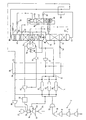
- a first flow of air is compressed in a first train 2 of a chosen number of compression stages 4, 6, 8, 10 and 12.
- Each of the compression stages 4, 6, 8, 10 and 12 has its own after-cooler (not shown) immediately downstream thereof in order to remove heat of compression from the air.
- Each after-cooler may take the form of an indirect heat exchanger, although it is sometimes preferred to employ a direct contact water chiller as the after-cooler immediately downstream of the final stage 12.
- all five of the compression stages, 4, 6, 8, 10 and 12 may be located in a single housing and form a single main compressor.
- the most downstream stage 12 or the downstream stages 10 and 12 may be located in a separate housing and form a separate compressor.
- the first fully compressed flow of air passes, typically at a temperature in the range of 2 to 20 degrees Celsius and typically at a pressure in the range of 8 to 14 bar absolute, to a purification unit 14 in which it is purified by adsorption.
- the purification unit 14 is arranged so as to purify not only the first flow of air but also a second flow of compressed air.
- the second flow of compressed air is taken from an air compressor 18 forming part of a gas turbine 16 including, in addition to the compressor 18, a combustion chamber 20 and a turbo-expander 22.
- the gas turbine 16 is arranged such that air from the compressor 18 and fuel gas (from a source described below) are sent to the combustion chamber 20 and the resulting combustion products are expanded with the performance of external work by the turbo-expander 22.
- the external work performed is typically the generation of electricity.
- the air compressor 18 includes a train of two or more compression stages 24 and 26. A bleed of air is withdrawn from the final or most downstream of the compression stages 24 and 26 and is cooled to ambient temperature or a temperature typically within the range of 2 to 20 degrees Celsius by passage through an after-cooler (not shown) typically in the form of a direct contact water chiller. The resulting chilled air flow forms a second flow of air that is sent to the purification unit 14. Typically, it enters the purification unit 14 at a pressure of 20 bar absolute, depending on the operating pressure of the gas turbine 16.
- the purification unit 14 is shown only schematically in the drawing, various valves and pipes having been omitted.
- the unit 14 includes three pressure vessels 28, 30 and 32, each housing a bed or beds of adsorbent for purifying the first and second flows of air.
- the arrangement is such that while one of the vessels 28, 30 and 32 is being used to purify the first flow of air, a second one is being used to purify the second flow of air, and a third or remaining one is being regenerated.
- the purification is effected by adsorption of impurities, particularly water vapour, carbon dioxide and hydrocarbons having two or more carbon atoms from the incoming air.
- a bed of activated alumina, or an upstream bed of activated alumina and a downstream bed of 13X zeolite are employed for this purpose.
- Regeneration of one of the vessels, 28, 30, and 32 which is not on-line may be effected by subjecting the adsorbent therein to a pressure markedly lower than the adsorption pressure or a temperature markedly higher than the adsorption temperature.
- the former technique is known as pressure swing adsorption and the latter as temperature swing adsorption.
- the design of temperature swing adsorption and pressure swing adsorption processes for purification of air is well known in the art and the purification unit 14 shall not be described in further detail except in one respect.
- the adsorption unit 14 has two vessels on adsorption duty at any one time for each vessel that is off-line being regenerated (or having been regenerated).
- This arrangement is made possible because the second flow is at a substantially higher pressure than the first flow of air. Since the flows are approximately equal, and since each of the vessels 28, 30 and 32 contain the same amount of adsorbent, by the time that impurities are about to break through the adsorbent bed or beds in the chosen one of the vessels 28, 30 and 32 which receives the first flow of air, the adsorbent or adsorbents in which the second flow of air is being purified still has available adsorption capacity.
- the second flow of gas can be switched from the second vessel to the third vessel which contains regenerated adsorbent(s). It can thus be appreciated that the first and second flows of air can be purified simultaneously with one another in the purification unit 14 and supplied continuously for separation.
- the thus purified first flow of air follows a flow path 34 which extends through a main heat exchanger 36 from its warm end 38 to its cold end 39.
- the air is thus cooled (by indirect heat exchange with returning streams) to a cryogenic temperature a little above that at which it is rectified.
- the resulting cooled first flow of compressed air is separated in an arrangement of a double rectification column 40 and a further rectification column 42.
- the double rectification column 40 includes a higher pressure column 44 and a lower pressure column 46.
- the lower pressure column 46 is provided with a first reboiler-condenser 48 in a bottom region 50 thereof and a second reboiler-condenser 51 in an intermediate region 54 thereof.
- the further rectification column 52 is provided with a further reboiler-condenser 56 in a bottom region 58 thereof and a condenser 60 associated with a top region 63 thereof.
- the first flow of cooled air passes from the cold end 39 of the main heat exchanger 36 through the first reboiler-condenser 48 associated with the lower pressure column 46.
- the purified second flow of compressed air flows through the main heat exchanger 36 from its warm end 38 to its cold end 39 and is thereby cooled to a cryogenic temperature.
- the resulting cooled second purified flow of compressed air is expanded in an expansion turbine 41 with the performance of external work.
- the thus expanded second purified flow of air is exhausted from the expansion turbine 41 at essentially the same pressure as that at which the first purified flow of compressed air leaves the cold end 39 of the main heat exchanger 36.
- the two flows of compressed air are united upstream of the first condenser-reboiler 56.
- the combined flows of air are partially condensed by indirect heat exchange with the bottom liquid fraction that is separated in the lower pressure column 46.
- Reboil that is an upward flow of vapour, is thereby created in the lower pressure column 46.
- the partially condensed flow of air passes out of the first reboiler-condenser 48 and is introduced through an inlet 62 into a bottom region of the higher pressure column 44.
- a minor part of the second flow of compressed air is withdrawn from an intermediate region of the main heat exchanger 36, is passed through an expansion valve 43 so as to reduce its pressure to essentially the operating pressure of the higher pressure column 44 and is introduced into the column 44 through an inlet 45 at an intermediate level thereof.
- Nitrogen vapour is separated in the higher pressure column 44 from the air introduced through the inlets 62 and 45. The nitrogen collects at the top of the higher pressure column 44.
- An oxygen-enriched liquid fraction collects at the bottom of the higher pressure column 44.
- a stream of the oxygen-enriched liquid air fraction is withdrawn from the bottom of the higher pressure column 44 through an outlet 64, is sub-cooled by passage through a further heat exchanger 66 and is expanded, that is reduced in pressure, by passage through a Joule-Thomson or throttling valve 68.
- the resulting expanded stream of oxygen-enriched liquid air is introduced into an intermediate region of the further rectification column 42 for separation therein.
- a part of the nitrogen vapour fraction obtained at the top of the higher pressure column 44 is condensed in the further condenser-reboiler 56.
- the nitrogen condensate is returned to the higher pressure column 44 as reflux.
- Some nitrogen condensate (whether formed in the condenser-reboiler 56, or otherwise, is preferably sub-cooled by passage through the further heat exchanger 66 (although this subcooling is not illustrated in the drawing), is expanded by passage through a Joule-Thomson or throttling valve 72 and is introduced into the top of the lower pressure column 46 through an inlet 74 as a reflux stream.
- the oxygen-enriched liquid air stream introduced into the further rectification column 42 is separated therein into a bottom oxygen-enriched liquid air fraction, usually containing a greater mole fraction of oxygen than the feed to the column 42, and a top nitrogen fraction, typically but not necessarily, impure.
- An upward flow of vapour in the further rectification column 42 is formed by reboiling of the bottom liquid fraction in the reboiler-condenser 56.
- the necessary heating of the reboiler-condenser 56 is effected by indirect heat exchange with the condensing stream of the top nitrogen fraction formed in the higher pressure column 44.
- a stream of the bottom oxygen-enriched liquid fraction is withdrawn from the bottom region of this column, expanding it through a Joule-Thomson or throttling valve 76 and condensing it in the condenser 60 by indirect heat exchange with a flow of the top nitrogen fraction that is obtained in the further rectification column 42.
- a part of the resulting condensate is expanded through a Joule-Thomson or throttling valve 78 and is introduced into an upper region of the lower pressure column 46 through an inlet 80 so as to augment the reflux in all but the uppermost region of the column 46.
- this stream of condensate may be sub-cooled by passage through the further heat exchanger 66. The remainder of the condensate serves as reflux for the further rectification column 42.
- the oxygen-enriched liquid stream is typically totally vaporised in the condenser 60 and is introduced through the inlet 82 into the lower pressure column 46 as a feed stream to be separated therein.
- the feed stream is separated into a impure liquid oxygen fraction, typically containing 95% by volume of oxygen, which collects at the bottom of the lower pressure column 46 and a top nitrogen fraction typically containing less than 0.5% by volume of oxygen impurity which collects at the top of the lower pressure column 46.
- passage of the first flow of air through the reboiler-condenser 48 creates an upward vapour flow in the lower pressure column 46.
- the vapour flow in the upper regions of the lower pressure column 46 is augmented by operation of the second reboiler-condenser 51.
- the reboiler-condenser 51 is heated by means of a further stream of the nitrogen that is separated in the higher pressure column 44.
- the nitrogen is condensed and the resulting condensate is used as reflux in the higher pressure and lower pressure columns 44 and 46, respectively.
- the condensation of the nitrogen in the second reboiler-condenser 51 may be incomplete and uncondensed vapour may pass into a product oxygen vaporiser 84 in which it is condensed by indirect heat exchange, as described below, with vaporising oxygen product.
- An impure oxygen product is withdrawn through an outlet 86 from the bottom region 50 of the lower pressure column 46.
- the impure liquid oxygen product stream flows through a throttling or Joule-Thomson valve 88 into the vaporiser 84 in which it is vaporised as aforesaid, by heat exchange with a stream of nitrogen vapour passing out of the second reboiler-condenser 51 in uncondensed state.
- the nitrogen is condensed and may, as shown, be combined with the nitrogen which is condensed in the second reboiler-condenser 51.
- An alternative to the illustrated arrangement is to send the nitrogen vapour to the vaporiser 84 directly and not via the second reboiler-condenser 51.
- the impure liquid oxygen product is not totally vaporised in the vaporiser 84, about 20% of it remaining in the liquid state.
- the resulting oxygen vapour is returned through the main heat exchanger 36 from its cold end 39 to its warm end 38 and is compressed to a pressure of, say, 80 bar in an oxygen-compressor 90.
- the resulting compressed oxygen is supplied to a partial oxidation unit 92.
- a fuel such as coal is also supplied to the partial oxidation unit 92.
- Fuel gas is formed in the partial oxidation unit 92.
- a stream of fuel gas is taken therefrom, is purified (by means not shown) and is sent to the combustion chamber 20 of the gas turbine 16 for combustion therein so as to form the hot combustion gases that are expanded by the turbo-expander 22.
- a stream of the residual liquid oxygen product is withdrawn from the vaporiser 84 and is pressurised by a liquid oxygen pump 94 to a pressure typically in the order of 40 bar.
- the resulting pressurised oxygen stream is passed through the main heat exchanger 36 from its cold end 39 to its warm end 38. Typically, it is combined with the compressed oxygen product in or downstream of the oxygen compressor 90.
- a stream of nitrogen product is withdrawn through an outlet 96 at the top of the lower pressure column 46 and flows through the heat exchanger 66 thereby providing the necessary cooling for the stream or streams that are sub-cooled therein, and downstream of the heat exchanger 66 through the main heat exchanger 66 from its cold end 39 to its warm end 38.
- a part of the resulting nitrogen stream is taken for bed regeneration purposes in the purification unit 14.
- the remainder of the nitrogen stream is compressed in a nitrogen compressor 98 to the operating pressure of the combustion chamber 20 of the gas turbine 16 and is introduced into the combustion chamber 20 or the turbo-expander 22 so as to reduce NOx formation during operation of the gas turbine 16.
- Moist nitrogen gas may be returned from the purification unit 14 to the nitrogen upstream of the compressor 98.
- the higher pressure column 44 has an operating pressure of 160 psia (10.9 bar) at its bottom; the lower pressure column 46 has an operating pressure of 72 psia (4.9 bar) at its top; the further rectification column 42 has an operating pressure of 111 psia (7.5 bar) at its top, and the oxygen vaporiser 84 has an operating pressure of 3.8 bar.
Applications Claiming Priority (2)
| Application Number | Priority Date | Filing Date | Title |
|---|---|---|---|
| GB0002086 | 2000-01-28 | ||
| GB0002086A GB0002086D0 (en) | 2000-01-28 | 2000-01-28 | Air separation |
Publications (2)
| Publication Number | Publication Date |
|---|---|
| EP1120617A2 true EP1120617A2 (fr) | 2001-08-01 |
| EP1120617A3 EP1120617A3 (fr) | 2002-08-28 |
Family
ID=9884601
Family Applications (1)
| Application Number | Title | Priority Date | Filing Date |
|---|---|---|---|
| EP01300191A Withdrawn EP1120617A3 (fr) | 2000-01-28 | 2001-01-10 | Séparation de l'air |
Country Status (2)
| Country | Link |
|---|---|
| EP (1) | EP1120617A3 (fr) |
| GB (1) | GB0002086D0 (fr) |
Cited By (3)
| Publication number | Priority date | Publication date | Assignee | Title |
|---|---|---|---|---|
| FR2823256A1 (fr) * | 2001-04-10 | 2002-10-11 | Air Liquide | Procede d'alimentation en azote impur de la chambre de combusti0n d'une turbine a gaz combinee a une unite de distillation d'air, et installation de production d'energie electrique correspondante |
| FR2831250A1 (fr) * | 2002-02-25 | 2003-04-25 | Air Liquide | Procede et appareil de separation d'air par distillation cryogenique |
| CN104165495A (zh) * | 2014-06-11 | 2014-11-26 | 西亚特工业气体工程(杭州)有限公司 | 富氧助燃技术新工艺 |
Citations (5)
| Publication number | Priority date | Publication date | Assignee | Title |
|---|---|---|---|---|
| US4806136A (en) * | 1987-12-15 | 1989-02-21 | Union Carbide Corporation | Air separation method with integrated gas turbine |
| DE3908505A1 (de) * | 1988-03-15 | 1989-09-28 | Voest Alpine Ind Anlagen | Verfahren zur gewinnung von fluessig-roheisen in einem einschmelzvergaser |
| EP0633438A1 (fr) * | 1993-07-05 | 1995-01-11 | The BOC Group plc | Séparation de l'air |
| EP0717249A2 (fr) * | 1994-12-16 | 1996-06-19 | The BOC Group plc | Séparation d'air |
| EP1199532A1 (fr) * | 2000-10-20 | 2002-04-24 | Linde Aktiengesellschaft | Système de séparation d'air cryogénique à trois colonnes |
-
2000
- 2000-01-28 GB GB0002086A patent/GB0002086D0/en not_active Ceased
-
2001
- 2001-01-10 EP EP01300191A patent/EP1120617A3/fr not_active Withdrawn
Patent Citations (5)
| Publication number | Priority date | Publication date | Assignee | Title |
|---|---|---|---|---|
| US4806136A (en) * | 1987-12-15 | 1989-02-21 | Union Carbide Corporation | Air separation method with integrated gas turbine |
| DE3908505A1 (de) * | 1988-03-15 | 1989-09-28 | Voest Alpine Ind Anlagen | Verfahren zur gewinnung von fluessig-roheisen in einem einschmelzvergaser |
| EP0633438A1 (fr) * | 1993-07-05 | 1995-01-11 | The BOC Group plc | Séparation de l'air |
| EP0717249A2 (fr) * | 1994-12-16 | 1996-06-19 | The BOC Group plc | Séparation d'air |
| EP1199532A1 (fr) * | 2000-10-20 | 2002-04-24 | Linde Aktiengesellschaft | Système de séparation d'air cryogénique à trois colonnes |
Cited By (6)
| Publication number | Priority date | Publication date | Assignee | Title |
|---|---|---|---|---|
| FR2823256A1 (fr) * | 2001-04-10 | 2002-10-11 | Air Liquide | Procede d'alimentation en azote impur de la chambre de combusti0n d'une turbine a gaz combinee a une unite de distillation d'air, et installation de production d'energie electrique correspondante |
| EP1249676A1 (fr) * | 2001-04-10 | 2002-10-16 | L'air Liquide, S.A. à Directoire et Conseil de Surveillance pour l'Etude et l'Exploitation des Procédés Georges Claude | Procédé d'alimentation en azote impur de la chambre de combustion d'une turbine à gaz combinée à une unité de distillation d'air, et installation de production d'énergie électrique correspondante |
| US6607582B2 (en) | 2001-04-10 | 2003-08-19 | L'air Liquide - Societe Anonyme A Directoire Et Conseil De Surveillance Pour L'etude Et L'exploitation Des Procedes Georges Claude | Method of feeding, with impure nitrogen, the combustion chamber of a gas turbine combined with an air distillation unit, and corresponding electricity generation plant |
| FR2831250A1 (fr) * | 2002-02-25 | 2003-04-25 | Air Liquide | Procede et appareil de separation d'air par distillation cryogenique |
| CN104165495A (zh) * | 2014-06-11 | 2014-11-26 | 西亚特工业气体工程(杭州)有限公司 | 富氧助燃技术新工艺 |
| CN104165495B (zh) * | 2014-06-11 | 2016-04-20 | 西亚特工业气体科技(杭州)有限公司 | 富氧助燃技术新工艺 |
Also Published As
| Publication number | Publication date |
|---|---|
| GB0002086D0 (en) | 2000-03-22 |
| EP1120617A3 (fr) | 2002-08-28 |
Similar Documents
| Publication | Publication Date | Title |
|---|---|---|
| US5123249A (en) | Air separation | |
| US10969168B2 (en) | System and method for enhanced recovery of argon and oxygen from a nitrogen producing cryogenic air separation unit | |
| EP0633438A1 (fr) | Séparation de l'air | |
| US5546766A (en) | Air separation | |
| CA3097179C (fr) | Systeme et procede de recuperation assistee d'argon et d'oxygene a partir d'une unite de separation d'air cryogenique de production d'azote | |
| CA3097145A1 (fr) | Systeme et procede de recuperation amelioree d'argon et d'oxygene a partir d'une unite de separation d'air cryogenique produisant de l'azote | |
| EP0384688B1 (fr) | Séparation d'air | |
| US5331818A (en) | Air separation | |
| US5657644A (en) | Air separation | |
| JPH07198249A (ja) | 空気を分離するための方法および装置 | |
| US5644933A (en) | Air separation | |
| US5309721A (en) | Air separation | |
| US6305191B1 (en) | Separation of air | |
| JPH11325717A (ja) | 空気の分離 | |
| EP1030148B1 (fr) | Séparation des gaz de l'air | |
| EP1120617A2 (fr) | Séparation de l'air | |
| EP0831284B1 (fr) | Séparation d'air | |
| US6170291B1 (en) | Separation of air | |
| EP1120616A2 (fr) | Méthode de séparation de l'air |
Legal Events
| Date | Code | Title | Description |
|---|---|---|---|
| PUAI | Public reference made under article 153(3) epc to a published international application that has entered the european phase |
Free format text: ORIGINAL CODE: 0009012 |
|
| AK | Designated contracting states |
Kind code of ref document: A2 Designated state(s): AT BE CH CY DE DK ES FI FR GB GR IE IT LI LU MC NL PT SE TR |
|
| AX | Request for extension of the european patent |
Free format text: AL;LT;LV;MK;RO;SI |
|
| PUAL | Search report despatched |
Free format text: ORIGINAL CODE: 0009013 |
|
| AK | Designated contracting states |
Kind code of ref document: A3 Designated state(s): AT BE CH CY DE DK ES FI FR GB GR IE IT LI LU MC NL PT SE TR |
|
| AX | Request for extension of the european patent |
Free format text: AL;LT;LV;MK;RO;SI |
|
| AKX | Designation fees paid | ||
| REG | Reference to a national code |
Ref country code: DE Ref legal event code: 8566 |
|
| STAA | Information on the status of an ep patent application or granted ep patent |
Free format text: STATUS: THE APPLICATION IS DEEMED TO BE WITHDRAWN |
|
| 18D | Application deemed to be withdrawn |
Effective date: 20030301 |