EP0793070A2 - Intégration d'une turbine à combustion à haute température et d'un système de séparation d'air - Google Patents
Intégration d'une turbine à combustion à haute température et d'un système de séparation d'air Download PDFInfo
- Publication number
- EP0793070A2 EP0793070A2 EP97300573A EP97300573A EP0793070A2 EP 0793070 A2 EP0793070 A2 EP 0793070A2 EP 97300573 A EP97300573 A EP 97300573A EP 97300573 A EP97300573 A EP 97300573A EP 0793070 A2 EP0793070 A2 EP 0793070A2
- Authority
- EP
- European Patent Office
- Prior art keywords
- air
- nitrogen
- cooled
- pressure
- compressed air
- Prior art date
- Legal status (The legal status is an assumption and is not a legal conclusion. Google has not performed a legal analysis and makes no representation as to the accuracy of the status listed.)
- Withdrawn
Links
Images


Classifications
-
- F—MECHANICAL ENGINEERING; LIGHTING; HEATING; WEAPONS; BLASTING
- F25—REFRIGERATION OR COOLING; COMBINED HEATING AND REFRIGERATION SYSTEMS; HEAT PUMP SYSTEMS; MANUFACTURE OR STORAGE OF ICE; LIQUEFACTION SOLIDIFICATION OF GASES
- F25J—LIQUEFACTION, SOLIDIFICATION OR SEPARATION OF GASES OR GASEOUS OR LIQUEFIED GASEOUS MIXTURES BY PRESSURE AND COLD TREATMENT OR BY BRINGING THEM INTO THE SUPERCRITICAL STATE
- F25J3/00—Processes or apparatus for separating the constituents of gaseous or liquefied gaseous mixtures involving the use of liquefaction or solidification
- F25J3/02—Processes or apparatus for separating the constituents of gaseous or liquefied gaseous mixtures involving the use of liquefaction or solidification by rectification, i.e. by continuous interchange of heat and material between a vapour stream and a liquid stream
- F25J3/04—Processes or apparatus for separating the constituents of gaseous or liquefied gaseous mixtures involving the use of liquefaction or solidification by rectification, i.e. by continuous interchange of heat and material between a vapour stream and a liquid stream for air
- F25J3/04521—Coupling of the air fractionation unit to an air gas-consuming unit, so-called integrated processes
- F25J3/04612—Heat exchange integration with process streams, e.g. from the air gas consuming unit
- F25J3/04618—Heat exchange integration with process streams, e.g. from the air gas consuming unit for cooling an air stream fed to the air fractionation unit
-
- F—MECHANICAL ENGINEERING; LIGHTING; HEATING; WEAPONS; BLASTING
- F02—COMBUSTION ENGINES; HOT-GAS OR COMBUSTION-PRODUCT ENGINE PLANTS
- F02C—GAS-TURBINE PLANTS; AIR INTAKES FOR JET-PROPULSION PLANTS; CONTROLLING FUEL SUPPLY IN AIR-BREATHING JET-PROPULSION PLANTS
- F02C7/00—Features, components parts, details or accessories, not provided for in, or of interest apart form groups F02C1/00 - F02C6/00; Air intakes for jet-propulsion plants
- F02C7/12—Cooling of plants
-
- F—MECHANICAL ENGINEERING; LIGHTING; HEATING; WEAPONS; BLASTING
- F01—MACHINES OR ENGINES IN GENERAL; ENGINE PLANTS IN GENERAL; STEAM ENGINES
- F01K—STEAM ENGINE PLANTS; STEAM ACCUMULATORS; ENGINE PLANTS NOT OTHERWISE PROVIDED FOR; ENGINES USING SPECIAL WORKING FLUIDS OR CYCLES
- F01K23/00—Plants characterised by more than one engine delivering power external to the plant, the engines being driven by different fluids
- F01K23/02—Plants characterised by more than one engine delivering power external to the plant, the engines being driven by different fluids the engine cycles being thermally coupled
- F01K23/06—Plants characterised by more than one engine delivering power external to the plant, the engines being driven by different fluids the engine cycles being thermally coupled combustion heat from one cycle heating the fluid in another cycle
- F01K23/067—Plants characterised by more than one engine delivering power external to the plant, the engines being driven by different fluids the engine cycles being thermally coupled combustion heat from one cycle heating the fluid in another cycle the combustion heat coming from a gasification or pyrolysis process, e.g. coal gasification
- F01K23/068—Plants characterised by more than one engine delivering power external to the plant, the engines being driven by different fluids the engine cycles being thermally coupled combustion heat from one cycle heating the fluid in another cycle the combustion heat coming from a gasification or pyrolysis process, e.g. coal gasification in combination with an oxygen producing plant, e.g. an air separation plant
-
- F—MECHANICAL ENGINEERING; LIGHTING; HEATING; WEAPONS; BLASTING
- F02—COMBUSTION ENGINES; HOT-GAS OR COMBUSTION-PRODUCT ENGINE PLANTS
- F02C—GAS-TURBINE PLANTS; AIR INTAKES FOR JET-PROPULSION PLANTS; CONTROLLING FUEL SUPPLY IN AIR-BREATHING JET-PROPULSION PLANTS
- F02C3/00—Gas-turbine plants characterised by the use of combustion products as the working fluid
- F02C3/20—Gas-turbine plants characterised by the use of combustion products as the working fluid using a special fuel, oxidant, or dilution fluid to generate the combustion products
-
- F—MECHANICAL ENGINEERING; LIGHTING; HEATING; WEAPONS; BLASTING
- F02—COMBUSTION ENGINES; HOT-GAS OR COMBUSTION-PRODUCT ENGINE PLANTS
- F02C—GAS-TURBINE PLANTS; AIR INTAKES FOR JET-PROPULSION PLANTS; CONTROLLING FUEL SUPPLY IN AIR-BREATHING JET-PROPULSION PLANTS
- F02C6/00—Plural gas-turbine plants; Combinations of gas-turbine plants with other apparatus; Adaptations of gas- turbine plants for special use
- F02C6/04—Gas-turbine plants providing heated or pressurised working fluid for other apparatus, e.g. without mechanical power output
- F02C6/10—Gas-turbine plants providing heated or pressurised working fluid for other apparatus, e.g. without mechanical power output supplying working fluid to a user, e.g. a chemical process, which returns working fluid to a turbine of the plant
-
- F—MECHANICAL ENGINEERING; LIGHTING; HEATING; WEAPONS; BLASTING
- F25—REFRIGERATION OR COOLING; COMBINED HEATING AND REFRIGERATION SYSTEMS; HEAT PUMP SYSTEMS; MANUFACTURE OR STORAGE OF ICE; LIQUEFACTION SOLIDIFICATION OF GASES
- F25J—LIQUEFACTION, SOLIDIFICATION OR SEPARATION OF GASES OR GASEOUS OR LIQUEFIED GASEOUS MIXTURES BY PRESSURE AND COLD TREATMENT OR BY BRINGING THEM INTO THE SUPERCRITICAL STATE
- F25J3/00—Processes or apparatus for separating the constituents of gaseous or liquefied gaseous mixtures involving the use of liquefaction or solidification
- F25J3/02—Processes or apparatus for separating the constituents of gaseous or liquefied gaseous mixtures involving the use of liquefaction or solidification by rectification, i.e. by continuous interchange of heat and material between a vapour stream and a liquid stream
- F25J3/04—Processes or apparatus for separating the constituents of gaseous or liquefied gaseous mixtures involving the use of liquefaction or solidification by rectification, i.e. by continuous interchange of heat and material between a vapour stream and a liquid stream for air
- F25J3/04006—Providing pressurised feed air or process streams within or from the air fractionation unit
- F25J3/04012—Providing pressurised feed air or process streams within or from the air fractionation unit by compression of warm gaseous streams; details of intake or interstage cooling
- F25J3/04018—Providing pressurised feed air or process streams within or from the air fractionation unit by compression of warm gaseous streams; details of intake or interstage cooling of main feed air
-
- F—MECHANICAL ENGINEERING; LIGHTING; HEATING; WEAPONS; BLASTING
- F25—REFRIGERATION OR COOLING; COMBINED HEATING AND REFRIGERATION SYSTEMS; HEAT PUMP SYSTEMS; MANUFACTURE OR STORAGE OF ICE; LIQUEFACTION SOLIDIFICATION OF GASES
- F25J—LIQUEFACTION, SOLIDIFICATION OR SEPARATION OF GASES OR GASEOUS OR LIQUEFIED GASEOUS MIXTURES BY PRESSURE AND COLD TREATMENT OR BY BRINGING THEM INTO THE SUPERCRITICAL STATE
- F25J3/00—Processes or apparatus for separating the constituents of gaseous or liquefied gaseous mixtures involving the use of liquefaction or solidification
- F25J3/02—Processes or apparatus for separating the constituents of gaseous or liquefied gaseous mixtures involving the use of liquefaction or solidification by rectification, i.e. by continuous interchange of heat and material between a vapour stream and a liquid stream
- F25J3/04—Processes or apparatus for separating the constituents of gaseous or liquefied gaseous mixtures involving the use of liquefaction or solidification by rectification, i.e. by continuous interchange of heat and material between a vapour stream and a liquid stream for air
- F25J3/04006—Providing pressurised feed air or process streams within or from the air fractionation unit
- F25J3/04012—Providing pressurised feed air or process streams within or from the air fractionation unit by compression of warm gaseous streams; details of intake or interstage cooling
- F25J3/0403—Providing pressurised feed air or process streams within or from the air fractionation unit by compression of warm gaseous streams; details of intake or interstage cooling of nitrogen
-
- F—MECHANICAL ENGINEERING; LIGHTING; HEATING; WEAPONS; BLASTING
- F25—REFRIGERATION OR COOLING; COMBINED HEATING AND REFRIGERATION SYSTEMS; HEAT PUMP SYSTEMS; MANUFACTURE OR STORAGE OF ICE; LIQUEFACTION SOLIDIFICATION OF GASES
- F25J—LIQUEFACTION, SOLIDIFICATION OR SEPARATION OF GASES OR GASEOUS OR LIQUEFIED GASEOUS MIXTURES BY PRESSURE AND COLD TREATMENT OR BY BRINGING THEM INTO THE SUPERCRITICAL STATE
- F25J3/00—Processes or apparatus for separating the constituents of gaseous or liquefied gaseous mixtures involving the use of liquefaction or solidification
- F25J3/02—Processes or apparatus for separating the constituents of gaseous or liquefied gaseous mixtures involving the use of liquefaction or solidification by rectification, i.e. by continuous interchange of heat and material between a vapour stream and a liquid stream
- F25J3/04—Processes or apparatus for separating the constituents of gaseous or liquefied gaseous mixtures involving the use of liquefaction or solidification by rectification, i.e. by continuous interchange of heat and material between a vapour stream and a liquid stream for air
- F25J3/04006—Providing pressurised feed air or process streams within or from the air fractionation unit
- F25J3/04078—Providing pressurised feed air or process streams within or from the air fractionation unit providing pressurized products by liquid compression and vaporisation with cold recovery, i.e. so-called internal compression
- F25J3/04084—Providing pressurised feed air or process streams within or from the air fractionation unit providing pressurized products by liquid compression and vaporisation with cold recovery, i.e. so-called internal compression of nitrogen
-
- F—MECHANICAL ENGINEERING; LIGHTING; HEATING; WEAPONS; BLASTING
- F25—REFRIGERATION OR COOLING; COMBINED HEATING AND REFRIGERATION SYSTEMS; HEAT PUMP SYSTEMS; MANUFACTURE OR STORAGE OF ICE; LIQUEFACTION SOLIDIFICATION OF GASES
- F25J—LIQUEFACTION, SOLIDIFICATION OR SEPARATION OF GASES OR GASEOUS OR LIQUEFIED GASEOUS MIXTURES BY PRESSURE AND COLD TREATMENT OR BY BRINGING THEM INTO THE SUPERCRITICAL STATE
- F25J3/00—Processes or apparatus for separating the constituents of gaseous or liquefied gaseous mixtures involving the use of liquefaction or solidification
- F25J3/02—Processes or apparatus for separating the constituents of gaseous or liquefied gaseous mixtures involving the use of liquefaction or solidification by rectification, i.e. by continuous interchange of heat and material between a vapour stream and a liquid stream
- F25J3/04—Processes or apparatus for separating the constituents of gaseous or liquefied gaseous mixtures involving the use of liquefaction or solidification by rectification, i.e. by continuous interchange of heat and material between a vapour stream and a liquid stream for air
- F25J3/04006—Providing pressurised feed air or process streams within or from the air fractionation unit
- F25J3/04078—Providing pressurised feed air or process streams within or from the air fractionation unit providing pressurized products by liquid compression and vaporisation with cold recovery, i.e. so-called internal compression
- F25J3/0409—Providing pressurised feed air or process streams within or from the air fractionation unit providing pressurized products by liquid compression and vaporisation with cold recovery, i.e. so-called internal compression of oxygen
-
- F—MECHANICAL ENGINEERING; LIGHTING; HEATING; WEAPONS; BLASTING
- F25—REFRIGERATION OR COOLING; COMBINED HEATING AND REFRIGERATION SYSTEMS; HEAT PUMP SYSTEMS; MANUFACTURE OR STORAGE OF ICE; LIQUEFACTION SOLIDIFICATION OF GASES
- F25J—LIQUEFACTION, SOLIDIFICATION OR SEPARATION OF GASES OR GASEOUS OR LIQUEFIED GASEOUS MIXTURES BY PRESSURE AND COLD TREATMENT OR BY BRINGING THEM INTO THE SUPERCRITICAL STATE
- F25J3/00—Processes or apparatus for separating the constituents of gaseous or liquefied gaseous mixtures involving the use of liquefaction or solidification
- F25J3/02—Processes or apparatus for separating the constituents of gaseous or liquefied gaseous mixtures involving the use of liquefaction or solidification by rectification, i.e. by continuous interchange of heat and material between a vapour stream and a liquid stream
- F25J3/04—Processes or apparatus for separating the constituents of gaseous or liquefied gaseous mixtures involving the use of liquefaction or solidification by rectification, i.e. by continuous interchange of heat and material between a vapour stream and a liquid stream for air
- F25J3/04006—Providing pressurised feed air or process streams within or from the air fractionation unit
- F25J3/04109—Arrangements of compressors and /or their drivers
- F25J3/04115—Arrangements of compressors and /or their drivers characterised by the type of prime driver, e.g. hot gas expander
- F25J3/04127—Gas turbine as the prime mechanical driver
-
- F—MECHANICAL ENGINEERING; LIGHTING; HEATING; WEAPONS; BLASTING
- F25—REFRIGERATION OR COOLING; COMBINED HEATING AND REFRIGERATION SYSTEMS; HEAT PUMP SYSTEMS; MANUFACTURE OR STORAGE OF ICE; LIQUEFACTION SOLIDIFICATION OF GASES
- F25J—LIQUEFACTION, SOLIDIFICATION OR SEPARATION OF GASES OR GASEOUS OR LIQUEFIED GASEOUS MIXTURES BY PRESSURE AND COLD TREATMENT OR BY BRINGING THEM INTO THE SUPERCRITICAL STATE
- F25J3/00—Processes or apparatus for separating the constituents of gaseous or liquefied gaseous mixtures involving the use of liquefaction or solidification
- F25J3/02—Processes or apparatus for separating the constituents of gaseous or liquefied gaseous mixtures involving the use of liquefaction or solidification by rectification, i.e. by continuous interchange of heat and material between a vapour stream and a liquid stream
- F25J3/04—Processes or apparatus for separating the constituents of gaseous or liquefied gaseous mixtures involving the use of liquefaction or solidification by rectification, i.e. by continuous interchange of heat and material between a vapour stream and a liquid stream for air
- F25J3/04151—Purification and (pre-)cooling of the feed air; recuperative heat-exchange with product streams
- F25J3/04163—Hot end purification of the feed air
- F25J3/04169—Hot end purification of the feed air by adsorption of the impurities
-
- F—MECHANICAL ENGINEERING; LIGHTING; HEATING; WEAPONS; BLASTING
- F25—REFRIGERATION OR COOLING; COMBINED HEATING AND REFRIGERATION SYSTEMS; HEAT PUMP SYSTEMS; MANUFACTURE OR STORAGE OF ICE; LIQUEFACTION SOLIDIFICATION OF GASES
- F25J—LIQUEFACTION, SOLIDIFICATION OR SEPARATION OF GASES OR GASEOUS OR LIQUEFIED GASEOUS MIXTURES BY PRESSURE AND COLD TREATMENT OR BY BRINGING THEM INTO THE SUPERCRITICAL STATE
- F25J3/00—Processes or apparatus for separating the constituents of gaseous or liquefied gaseous mixtures involving the use of liquefaction or solidification
- F25J3/02—Processes or apparatus for separating the constituents of gaseous or liquefied gaseous mixtures involving the use of liquefaction or solidification by rectification, i.e. by continuous interchange of heat and material between a vapour stream and a liquid stream
- F25J3/04—Processes or apparatus for separating the constituents of gaseous or liquefied gaseous mixtures involving the use of liquefaction or solidification by rectification, i.e. by continuous interchange of heat and material between a vapour stream and a liquid stream for air
- F25J3/04248—Generation of cold for compensating heat leaks or liquid production, e.g. by Joule-Thompson expansion
- F25J3/04284—Generation of cold for compensating heat leaks or liquid production, e.g. by Joule-Thompson expansion using internal refrigeration by open-loop gas work expansion, e.g. of intermediate or oxygen enriched (waste-)streams
- F25J3/0429—Generation of cold for compensating heat leaks or liquid production, e.g. by Joule-Thompson expansion using internal refrigeration by open-loop gas work expansion, e.g. of intermediate or oxygen enriched (waste-)streams of feed air, e.g. used as waste or product air or expanded into an auxiliary column
- F25J3/04296—Claude expansion, i.e. expanded into the main or high pressure column
-
- F—MECHANICAL ENGINEERING; LIGHTING; HEATING; WEAPONS; BLASTING
- F25—REFRIGERATION OR COOLING; COMBINED HEATING AND REFRIGERATION SYSTEMS; HEAT PUMP SYSTEMS; MANUFACTURE OR STORAGE OF ICE; LIQUEFACTION SOLIDIFICATION OF GASES
- F25J—LIQUEFACTION, SOLIDIFICATION OR SEPARATION OF GASES OR GASEOUS OR LIQUEFIED GASEOUS MIXTURES BY PRESSURE AND COLD TREATMENT OR BY BRINGING THEM INTO THE SUPERCRITICAL STATE
- F25J3/00—Processes or apparatus for separating the constituents of gaseous or liquefied gaseous mixtures involving the use of liquefaction or solidification
- F25J3/02—Processes or apparatus for separating the constituents of gaseous or liquefied gaseous mixtures involving the use of liquefaction or solidification by rectification, i.e. by continuous interchange of heat and material between a vapour stream and a liquid stream
- F25J3/04—Processes or apparatus for separating the constituents of gaseous or liquefied gaseous mixtures involving the use of liquefaction or solidification by rectification, i.e. by continuous interchange of heat and material between a vapour stream and a liquid stream for air
- F25J3/04248—Generation of cold for compensating heat leaks or liquid production, e.g. by Joule-Thompson expansion
- F25J3/04284—Generation of cold for compensating heat leaks or liquid production, e.g. by Joule-Thompson expansion using internal refrigeration by open-loop gas work expansion, e.g. of intermediate or oxygen enriched (waste-)streams
- F25J3/0429—Generation of cold for compensating heat leaks or liquid production, e.g. by Joule-Thompson expansion using internal refrigeration by open-loop gas work expansion, e.g. of intermediate or oxygen enriched (waste-)streams of feed air, e.g. used as waste or product air or expanded into an auxiliary column
- F25J3/04303—Lachmann expansion, i.e. expanded into oxygen producing or low pressure column
-
- F—MECHANICAL ENGINEERING; LIGHTING; HEATING; WEAPONS; BLASTING
- F25—REFRIGERATION OR COOLING; COMBINED HEATING AND REFRIGERATION SYSTEMS; HEAT PUMP SYSTEMS; MANUFACTURE OR STORAGE OF ICE; LIQUEFACTION SOLIDIFICATION OF GASES
- F25J—LIQUEFACTION, SOLIDIFICATION OR SEPARATION OF GASES OR GASEOUS OR LIQUEFIED GASEOUS MIXTURES BY PRESSURE AND COLD TREATMENT OR BY BRINGING THEM INTO THE SUPERCRITICAL STATE
- F25J3/00—Processes or apparatus for separating the constituents of gaseous or liquefied gaseous mixtures involving the use of liquefaction or solidification
- F25J3/02—Processes or apparatus for separating the constituents of gaseous or liquefied gaseous mixtures involving the use of liquefaction or solidification by rectification, i.e. by continuous interchange of heat and material between a vapour stream and a liquid stream
- F25J3/04—Processes or apparatus for separating the constituents of gaseous or liquefied gaseous mixtures involving the use of liquefaction or solidification by rectification, i.e. by continuous interchange of heat and material between a vapour stream and a liquid stream for air
- F25J3/04248—Generation of cold for compensating heat leaks or liquid production, e.g. by Joule-Thompson expansion
- F25J3/04333—Generation of cold for compensating heat leaks or liquid production, e.g. by Joule-Thompson expansion using quasi-closed loop internal vapor compression refrigeration cycles, e.g. of intermediate or oxygen enriched (waste-)streams
- F25J3/04351—Generation of cold for compensating heat leaks or liquid production, e.g. by Joule-Thompson expansion using quasi-closed loop internal vapor compression refrigeration cycles, e.g. of intermediate or oxygen enriched (waste-)streams of nitrogen
-
- F—MECHANICAL ENGINEERING; LIGHTING; HEATING; WEAPONS; BLASTING
- F25—REFRIGERATION OR COOLING; COMBINED HEATING AND REFRIGERATION SYSTEMS; HEAT PUMP SYSTEMS; MANUFACTURE OR STORAGE OF ICE; LIQUEFACTION SOLIDIFICATION OF GASES
- F25J—LIQUEFACTION, SOLIDIFICATION OR SEPARATION OF GASES OR GASEOUS OR LIQUEFIED GASEOUS MIXTURES BY PRESSURE AND COLD TREATMENT OR BY BRINGING THEM INTO THE SUPERCRITICAL STATE
- F25J3/00—Processes or apparatus for separating the constituents of gaseous or liquefied gaseous mixtures involving the use of liquefaction or solidification
- F25J3/02—Processes or apparatus for separating the constituents of gaseous or liquefied gaseous mixtures involving the use of liquefaction or solidification by rectification, i.e. by continuous interchange of heat and material between a vapour stream and a liquid stream
- F25J3/04—Processes or apparatus for separating the constituents of gaseous or liquefied gaseous mixtures involving the use of liquefaction or solidification by rectification, i.e. by continuous interchange of heat and material between a vapour stream and a liquid stream for air
- F25J3/04248—Generation of cold for compensating heat leaks or liquid production, e.g. by Joule-Thompson expansion
- F25J3/04375—Details relating to the work expansion, e.g. process parameter etc.
- F25J3/04393—Details relating to the work expansion, e.g. process parameter etc. using multiple or multistage gas work expansion
-
- F—MECHANICAL ENGINEERING; LIGHTING; HEATING; WEAPONS; BLASTING
- F25—REFRIGERATION OR COOLING; COMBINED HEATING AND REFRIGERATION SYSTEMS; HEAT PUMP SYSTEMS; MANUFACTURE OR STORAGE OF ICE; LIQUEFACTION SOLIDIFICATION OF GASES
- F25J—LIQUEFACTION, SOLIDIFICATION OR SEPARATION OF GASES OR GASEOUS OR LIQUEFIED GASEOUS MIXTURES BY PRESSURE AND COLD TREATMENT OR BY BRINGING THEM INTO THE SUPERCRITICAL STATE
- F25J3/00—Processes or apparatus for separating the constituents of gaseous or liquefied gaseous mixtures involving the use of liquefaction or solidification
- F25J3/02—Processes or apparatus for separating the constituents of gaseous or liquefied gaseous mixtures involving the use of liquefaction or solidification by rectification, i.e. by continuous interchange of heat and material between a vapour stream and a liquid stream
- F25J3/04—Processes or apparatus for separating the constituents of gaseous or liquefied gaseous mixtures involving the use of liquefaction or solidification by rectification, i.e. by continuous interchange of heat and material between a vapour stream and a liquid stream for air
- F25J3/04406—Processes or apparatus for separating the constituents of gaseous or liquefied gaseous mixtures involving the use of liquefaction or solidification by rectification, i.e. by continuous interchange of heat and material between a vapour stream and a liquid stream for air using a dual pressure main column system
- F25J3/04412—Processes or apparatus for separating the constituents of gaseous or liquefied gaseous mixtures involving the use of liquefaction or solidification by rectification, i.e. by continuous interchange of heat and material between a vapour stream and a liquid stream for air using a dual pressure main column system in a classical double column flowsheet, i.e. with thermal coupling by a main reboiler-condenser in the bottom of low pressure respectively top of high pressure column
-
- F—MECHANICAL ENGINEERING; LIGHTING; HEATING; WEAPONS; BLASTING
- F25—REFRIGERATION OR COOLING; COMBINED HEATING AND REFRIGERATION SYSTEMS; HEAT PUMP SYSTEMS; MANUFACTURE OR STORAGE OF ICE; LIQUEFACTION SOLIDIFICATION OF GASES
- F25J—LIQUEFACTION, SOLIDIFICATION OR SEPARATION OF GASES OR GASEOUS OR LIQUEFIED GASEOUS MIXTURES BY PRESSURE AND COLD TREATMENT OR BY BRINGING THEM INTO THE SUPERCRITICAL STATE
- F25J3/00—Processes or apparatus for separating the constituents of gaseous or liquefied gaseous mixtures involving the use of liquefaction or solidification
- F25J3/02—Processes or apparatus for separating the constituents of gaseous or liquefied gaseous mixtures involving the use of liquefaction or solidification by rectification, i.e. by continuous interchange of heat and material between a vapour stream and a liquid stream
- F25J3/04—Processes or apparatus for separating the constituents of gaseous or liquefied gaseous mixtures involving the use of liquefaction or solidification by rectification, i.e. by continuous interchange of heat and material between a vapour stream and a liquid stream for air
- F25J3/04472—Processes or apparatus for separating the constituents of gaseous or liquefied gaseous mixtures involving the use of liquefaction or solidification by rectification, i.e. by continuous interchange of heat and material between a vapour stream and a liquid stream for air using the cold from cryogenic liquids produced within the air fractionation unit and stored in internal or intermediate storages
- F25J3/04496—Processes or apparatus for separating the constituents of gaseous or liquefied gaseous mixtures involving the use of liquefaction or solidification by rectification, i.e. by continuous interchange of heat and material between a vapour stream and a liquid stream for air using the cold from cryogenic liquids produced within the air fractionation unit and stored in internal or intermediate storages for compensating variable air feed or variable product demand by alternating between periods of liquid storage and liquid assist
-
- F—MECHANICAL ENGINEERING; LIGHTING; HEATING; WEAPONS; BLASTING
- F25—REFRIGERATION OR COOLING; COMBINED HEATING AND REFRIGERATION SYSTEMS; HEAT PUMP SYSTEMS; MANUFACTURE OR STORAGE OF ICE; LIQUEFACTION SOLIDIFICATION OF GASES
- F25J—LIQUEFACTION, SOLIDIFICATION OR SEPARATION OF GASES OR GASEOUS OR LIQUEFIED GASEOUS MIXTURES BY PRESSURE AND COLD TREATMENT OR BY BRINGING THEM INTO THE SUPERCRITICAL STATE
- F25J3/00—Processes or apparatus for separating the constituents of gaseous or liquefied gaseous mixtures involving the use of liquefaction or solidification
- F25J3/02—Processes or apparatus for separating the constituents of gaseous or liquefied gaseous mixtures involving the use of liquefaction or solidification by rectification, i.e. by continuous interchange of heat and material between a vapour stream and a liquid stream
- F25J3/04—Processes or apparatus for separating the constituents of gaseous or liquefied gaseous mixtures involving the use of liquefaction or solidification by rectification, i.e. by continuous interchange of heat and material between a vapour stream and a liquid stream for air
- F25J3/04521—Coupling of the air fractionation unit to an air gas-consuming unit, so-called integrated processes
- F25J3/04527—Integration with an oxygen consuming unit, e.g. glass facility, waste incineration or oxygen based processes in general
- F25J3/04539—Integration with an oxygen consuming unit, e.g. glass facility, waste incineration or oxygen based processes in general for the H2/CO synthesis by partial oxidation or oxygen consuming reforming processes of fuels
- F25J3/04545—Integration with an oxygen consuming unit, e.g. glass facility, waste incineration or oxygen based processes in general for the H2/CO synthesis by partial oxidation or oxygen consuming reforming processes of fuels for the gasification of solid or heavy liquid fuels, e.g. integrated gasification combined cycle [IGCC]
-
- F—MECHANICAL ENGINEERING; LIGHTING; HEATING; WEAPONS; BLASTING
- F25—REFRIGERATION OR COOLING; COMBINED HEATING AND REFRIGERATION SYSTEMS; HEAT PUMP SYSTEMS; MANUFACTURE OR STORAGE OF ICE; LIQUEFACTION SOLIDIFICATION OF GASES
- F25J—LIQUEFACTION, SOLIDIFICATION OR SEPARATION OF GASES OR GASEOUS OR LIQUEFIED GASEOUS MIXTURES BY PRESSURE AND COLD TREATMENT OR BY BRINGING THEM INTO THE SUPERCRITICAL STATE
- F25J3/00—Processes or apparatus for separating the constituents of gaseous or liquefied gaseous mixtures involving the use of liquefaction or solidification
- F25J3/02—Processes or apparatus for separating the constituents of gaseous or liquefied gaseous mixtures involving the use of liquefaction or solidification by rectification, i.e. by continuous interchange of heat and material between a vapour stream and a liquid stream
- F25J3/04—Processes or apparatus for separating the constituents of gaseous or liquefied gaseous mixtures involving the use of liquefaction or solidification by rectification, i.e. by continuous interchange of heat and material between a vapour stream and a liquid stream for air
- F25J3/04521—Coupling of the air fractionation unit to an air gas-consuming unit, so-called integrated processes
- F25J3/04563—Integration with a nitrogen consuming unit, e.g. for purging, inerting, cooling or heating
- F25J3/04575—Integration with a nitrogen consuming unit, e.g. for purging, inerting, cooling or heating for a gas expansion plant, e.g. dilution of the combustion gas in a gas turbine
-
- F—MECHANICAL ENGINEERING; LIGHTING; HEATING; WEAPONS; BLASTING
- F25—REFRIGERATION OR COOLING; COMBINED HEATING AND REFRIGERATION SYSTEMS; HEAT PUMP SYSTEMS; MANUFACTURE OR STORAGE OF ICE; LIQUEFACTION SOLIDIFICATION OF GASES
- F25J—LIQUEFACTION, SOLIDIFICATION OR SEPARATION OF GASES OR GASEOUS OR LIQUEFIED GASEOUS MIXTURES BY PRESSURE AND COLD TREATMENT OR BY BRINGING THEM INTO THE SUPERCRITICAL STATE
- F25J3/00—Processes or apparatus for separating the constituents of gaseous or liquefied gaseous mixtures involving the use of liquefaction or solidification
- F25J3/02—Processes or apparatus for separating the constituents of gaseous or liquefied gaseous mixtures involving the use of liquefaction or solidification by rectification, i.e. by continuous interchange of heat and material between a vapour stream and a liquid stream
- F25J3/04—Processes or apparatus for separating the constituents of gaseous or liquefied gaseous mixtures involving the use of liquefaction or solidification by rectification, i.e. by continuous interchange of heat and material between a vapour stream and a liquid stream for air
- F25J3/04521—Coupling of the air fractionation unit to an air gas-consuming unit, so-called integrated processes
- F25J3/04593—The air gas consuming unit is also fed by an air stream
- F25J3/046—Completely integrated air feed compression, i.e. common MAC
-
- F—MECHANICAL ENGINEERING; LIGHTING; HEATING; WEAPONS; BLASTING
- F25—REFRIGERATION OR COOLING; COMBINED HEATING AND REFRIGERATION SYSTEMS; HEAT PUMP SYSTEMS; MANUFACTURE OR STORAGE OF ICE; LIQUEFACTION SOLIDIFICATION OF GASES
- F25J—LIQUEFACTION, SOLIDIFICATION OR SEPARATION OF GASES OR GASEOUS OR LIQUEFIED GASEOUS MIXTURES BY PRESSURE AND COLD TREATMENT OR BY BRINGING THEM INTO THE SUPERCRITICAL STATE
- F25J3/00—Processes or apparatus for separating the constituents of gaseous or liquefied gaseous mixtures involving the use of liquefaction or solidification
- F25J3/02—Processes or apparatus for separating the constituents of gaseous or liquefied gaseous mixtures involving the use of liquefaction or solidification by rectification, i.e. by continuous interchange of heat and material between a vapour stream and a liquid stream
- F25J3/04—Processes or apparatus for separating the constituents of gaseous or liquefied gaseous mixtures involving the use of liquefaction or solidification by rectification, i.e. by continuous interchange of heat and material between a vapour stream and a liquid stream for air
- F25J3/04521—Coupling of the air fractionation unit to an air gas-consuming unit, so-called integrated processes
- F25J3/04593—The air gas consuming unit is also fed by an air stream
- F25J3/04606—Partially integrated air feed compression, i.e. independent MAC for the air fractionation unit plus additional air feed from the air gas consuming unit
-
- F—MECHANICAL ENGINEERING; LIGHTING; HEATING; WEAPONS; BLASTING
- F25—REFRIGERATION OR COOLING; COMBINED HEATING AND REFRIGERATION SYSTEMS; HEAT PUMP SYSTEMS; MANUFACTURE OR STORAGE OF ICE; LIQUEFACTION SOLIDIFICATION OF GASES
- F25J—LIQUEFACTION, SOLIDIFICATION OR SEPARATION OF GASES OR GASEOUS OR LIQUEFIED GASEOUS MIXTURES BY PRESSURE AND COLD TREATMENT OR BY BRINGING THEM INTO THE SUPERCRITICAL STATE
- F25J3/00—Processes or apparatus for separating the constituents of gaseous or liquefied gaseous mixtures involving the use of liquefaction or solidification
- F25J3/02—Processes or apparatus for separating the constituents of gaseous or liquefied gaseous mixtures involving the use of liquefaction or solidification by rectification, i.e. by continuous interchange of heat and material between a vapour stream and a liquid stream
- F25J3/04—Processes or apparatus for separating the constituents of gaseous or liquefied gaseous mixtures involving the use of liquefaction or solidification by rectification, i.e. by continuous interchange of heat and material between a vapour stream and a liquid stream for air
- F25J3/04763—Start-up or control of the process; Details of the apparatus used
- F25J3/04769—Operation, control and regulation of the process; Instrumentation within the process
- F25J3/04812—Different modes, i.e. "runs" of operation
- F25J3/04836—Variable air feed, i.e. "load" or product demand during specified periods, e.g. during periods with high respectively low power costs
-
- F—MECHANICAL ENGINEERING; LIGHTING; HEATING; WEAPONS; BLASTING
- F25—REFRIGERATION OR COOLING; COMBINED HEATING AND REFRIGERATION SYSTEMS; HEAT PUMP SYSTEMS; MANUFACTURE OR STORAGE OF ICE; LIQUEFACTION SOLIDIFICATION OF GASES
- F25J—LIQUEFACTION, SOLIDIFICATION OR SEPARATION OF GASES OR GASEOUS OR LIQUEFIED GASEOUS MIXTURES BY PRESSURE AND COLD TREATMENT OR BY BRINGING THEM INTO THE SUPERCRITICAL STATE
- F25J2200/00—Processes or apparatus using separation by rectification
- F25J2200/20—Processes or apparatus using separation by rectification in an elevated pressure multiple column system wherein the lowest pressure column is at a pressure well above the minimum pressure needed to overcome pressure drop to reject the products to atmosphere
-
- F—MECHANICAL ENGINEERING; LIGHTING; HEATING; WEAPONS; BLASTING
- F25—REFRIGERATION OR COOLING; COMBINED HEATING AND REFRIGERATION SYSTEMS; HEAT PUMP SYSTEMS; MANUFACTURE OR STORAGE OF ICE; LIQUEFACTION SOLIDIFICATION OF GASES
- F25J—LIQUEFACTION, SOLIDIFICATION OR SEPARATION OF GASES OR GASEOUS OR LIQUEFIED GASEOUS MIXTURES BY PRESSURE AND COLD TREATMENT OR BY BRINGING THEM INTO THE SUPERCRITICAL STATE
- F25J2205/00—Processes or apparatus using other separation and/or other processing means
- F25J2205/02—Processes or apparatus using other separation and/or other processing means using simple phase separation in a vessel or drum
- F25J2205/04—Processes or apparatus using other separation and/or other processing means using simple phase separation in a vessel or drum in the feed line, i.e. upstream of the fractionation step
-
- F—MECHANICAL ENGINEERING; LIGHTING; HEATING; WEAPONS; BLASTING
- F25—REFRIGERATION OR COOLING; COMBINED HEATING AND REFRIGERATION SYSTEMS; HEAT PUMP SYSTEMS; MANUFACTURE OR STORAGE OF ICE; LIQUEFACTION SOLIDIFICATION OF GASES
- F25J—LIQUEFACTION, SOLIDIFICATION OR SEPARATION OF GASES OR GASEOUS OR LIQUEFIED GASEOUS MIXTURES BY PRESSURE AND COLD TREATMENT OR BY BRINGING THEM INTO THE SUPERCRITICAL STATE
- F25J2205/00—Processes or apparatus using other separation and/or other processing means
- F25J2205/60—Processes or apparatus using other separation and/or other processing means using adsorption on solid adsorbents, e.g. by temperature-swing adsorption [TSA] at the hot or cold end
- F25J2205/62—Purifying more than one feed stream in multiple adsorption vessels, e.g. for two feed streams at different pressures
-
- F—MECHANICAL ENGINEERING; LIGHTING; HEATING; WEAPONS; BLASTING
- F25—REFRIGERATION OR COOLING; COMBINED HEATING AND REFRIGERATION SYSTEMS; HEAT PUMP SYSTEMS; MANUFACTURE OR STORAGE OF ICE; LIQUEFACTION SOLIDIFICATION OF GASES
- F25J—LIQUEFACTION, SOLIDIFICATION OR SEPARATION OF GASES OR GASEOUS OR LIQUEFIED GASEOUS MIXTURES BY PRESSURE AND COLD TREATMENT OR BY BRINGING THEM INTO THE SUPERCRITICAL STATE
- F25J2240/00—Processes or apparatus involving steps for expanding of process streams
- F25J2240/02—Expansion of a process fluid in a work-extracting turbine (i.e. isentropic expansion), e.g. of the feed stream
- F25J2240/10—Expansion of a process fluid in a work-extracting turbine (i.e. isentropic expansion), e.g. of the feed stream the fluid being air
-
- F—MECHANICAL ENGINEERING; LIGHTING; HEATING; WEAPONS; BLASTING
- F25—REFRIGERATION OR COOLING; COMBINED HEATING AND REFRIGERATION SYSTEMS; HEAT PUMP SYSTEMS; MANUFACTURE OR STORAGE OF ICE; LIQUEFACTION SOLIDIFICATION OF GASES
- F25J—LIQUEFACTION, SOLIDIFICATION OR SEPARATION OF GASES OR GASEOUS OR LIQUEFIED GASEOUS MIXTURES BY PRESSURE AND COLD TREATMENT OR BY BRINGING THEM INTO THE SUPERCRITICAL STATE
- F25J2245/00—Processes or apparatus involving steps for recycling of process streams
- F25J2245/42—Processes or apparatus involving steps for recycling of process streams the recycled stream being nitrogen
-
- F—MECHANICAL ENGINEERING; LIGHTING; HEATING; WEAPONS; BLASTING
- F25—REFRIGERATION OR COOLING; COMBINED HEATING AND REFRIGERATION SYSTEMS; HEAT PUMP SYSTEMS; MANUFACTURE OR STORAGE OF ICE; LIQUEFACTION SOLIDIFICATION OF GASES
- F25J—LIQUEFACTION, SOLIDIFICATION OR SEPARATION OF GASES OR GASEOUS OR LIQUEFIED GASEOUS MIXTURES BY PRESSURE AND COLD TREATMENT OR BY BRINGING THEM INTO THE SUPERCRITICAL STATE
- F25J2290/00—Other details not covered by groups F25J2200/00 - F25J2280/00
- F25J2290/10—Mathematical formulae, modeling, plot or curves; Design methods
-
- Y—GENERAL TAGGING OF NEW TECHNOLOGICAL DEVELOPMENTS; GENERAL TAGGING OF CROSS-SECTIONAL TECHNOLOGIES SPANNING OVER SEVERAL SECTIONS OF THE IPC; TECHNICAL SUBJECTS COVERED BY FORMER USPC CROSS-REFERENCE ART COLLECTIONS [XRACs] AND DIGESTS
- Y02—TECHNOLOGIES OR APPLICATIONS FOR MITIGATION OR ADAPTATION AGAINST CLIMATE CHANGE
- Y02E—REDUCTION OF GREENHOUSE GAS [GHG] EMISSIONS, RELATED TO ENERGY GENERATION, TRANSMISSION OR DISTRIBUTION
- Y02E20/00—Combustion technologies with mitigation potential
- Y02E20/16—Combined cycle power plant [CCPP], or combined cycle gas turbine [CCGT]
- Y02E20/18—Integrated gasification combined cycle [IGCC], e.g. combined with carbon capture and storage [CCS]
-
- Y—GENERAL TAGGING OF NEW TECHNOLOGICAL DEVELOPMENTS; GENERAL TAGGING OF CROSS-SECTIONAL TECHNOLOGIES SPANNING OVER SEVERAL SECTIONS OF THE IPC; TECHNICAL SUBJECTS COVERED BY FORMER USPC CROSS-REFERENCE ART COLLECTIONS [XRACs] AND DIGESTS
- Y10—TECHNICAL SUBJECTS COVERED BY FORMER USPC
- Y10S—TECHNICAL SUBJECTS COVERED BY FORMER USPC CROSS-REFERENCE ART COLLECTIONS [XRACs] AND DIGESTS
- Y10S62/00—Refrigeration
- Y10S62/915—Combustion
Definitions
- the invention pertains to the integrated operation of high pressure combustion turbines with cryogenic air separation systems.
- Combustion turbines can be readily integrated with air separation systems to produce atmospheric gas products and electric power.
- the combustion turbine air compressor supplies compressed air for the turbine combustor and also may provide some or all of the compressed air feed to the air separation system.
- the combustion turbine is integrated with a cryogenic air separation system to provide oxygen and/or nitrogen products, and the combustion turbine and air separation systems can be integrated with a gasification process in a gasification combined cycle power generation system.
- GCC gasification combined cycle
- nitrogen integration is combined with air integration in which a portion of the feed air to the air separation unit is supplied by extracted air from the gas turbine compressor.
- This alternative mode defined as air and nitrogen integration, gives greater operating flexibility and allows for a higher degree of optimization during IGCC system operation at part load conditions.
- Combustion-based power generation systems including IGCC systems, are subject to periods of operation below system design capacity due to changes in ambient air temperature and/or the cyclic demand for electric power. During these periods, such systems operate below design efficiency.
- the equipment selection and process design of an IGCC system therefore must address steady-state operation at design capacity as well as operation at part load or turndown conditions.
- the air- and nitrogen-integrated IGCC system described above is a preferred option because of the potential for operating such a system at maximum overall efficiency, particularly when the system operates at part load or turndown conditions for significant periods.
- Cryogenic air separation processes can be designed specifically for integration with combustion turbines or gas turbines, and air separation processes having both air and nitrogen integration with combustion turbines are of particular utility.
- Most air separation processes in this service utilize the well-known double column distillation system for efficient recovery of oxygen and nitrogen products.
- US-A-3,731,495 discloses an air- and nitrogen-integrated combustion turbine system in which a portion of the air from the gas turbine compressor is further compressed, treated to remove gaseous impurities, cooled, and introduced in total into the high pressure column of a double column distillation system.
- US-A-4,019,314 describes an air- and nitrogen-integrated steam generation/combustion turbine system in which a portion of the air from the gas turbine compressor is further compressed and introduced into an air separation unit. Oxygen product is used in a coal gasification system which generates fuel for the combustion turbine.
- An air- and nitrogen-integrated combustion turbine system is disclosed by US-A-4,224,045 in which a portion of the air from the combustion turbine compressor is cooled and purified in a reversing heat exchanger.
- the cooled purified air is divided into a first and a second portion, the first portion is introduced into the high pressure column of a double column distillation system, and the second portion is warmed, work-expanded, and introduced into the low pressure column.
- the portion of air from the combustion turbine compressor is compressed further before cooling and purification.
- the portion of air from the combustion turbine compressor is (1) work expanded before cooling and purification or (2) work expanded after cooling and purification but before dividing the air for introduction into the low and high pressure columns.
- US-A-4,557,735 describes an air- and nitrogen-integrated combustion turbine system in which a portion of the air from the combustion turbine compressor is purified by adsorption and cooled to provide the sole feed to a double column distillation system via the high pressure column. A nitrogen product from the high pressure column is expanded to provide refrigeration, utilized to regenerate the feed adsorption system, compressed, and introduced into the combustor of the combustion turbine system.
- US-A-5,386,686 describes an air- and nitrogen-integrated combustion turbine system in which the oxygen content of the combined feed air and return nitrogen to the combustor is controlled by controlling the flow rate of the extracted air or the return nitrogen.
- Air- and nitrogen-integrated combustion turbine systems are described in US-A-5,406,786 in which the heat generated in feed air and oxygen product compression is used to humidify compressed air to the combustor of the combustion turbine system.
- the portion of air extracted from the combustion turbine compressor optionally is work-expanded before introduction into the air separation system.
- Nitrogen-integrated combustion turbine systems are described in US-A-5,081,845, US-A-5,410,869, and US-A-5,459,994, and in GB-A-2 067 668.
- High pressure oxygen and/or nitrogen products can be obtained by pumping liquid(s) withdrawn from a cryogenic air separation system and vaporizing the pressurized pumped liquids by heat transfer with cooling feed air streams as described by representative US-A-5,098,457, US-A-5,148,680, US-A-5,303,556, and US-A-5,355,682.
- Combustion turbine systems currently in operation typically supply combustion air at pressures up to 200 psia (1.4 MPa).
- New combustion turbine systems recently have been introduced which operate at higher pressures in which the combustion air is provided in the range of 240 to 440 psia (1.65 to 3.05 MPa).
- These new high pressure turbine systems operate at higher efficiencies than the lower pressure systems currently in operation, and offer the potential for improved integration with cryogenic air separation systems.
- Improved methods for the integration of such high pressure combustion turbines with cryogenic air separation systems are described in the invention disclosed below and defined by the claims which follow.
- An integrated combustion turbine/air separation process includes the steps of compressing air in a gas turbine air compressor, combusting a first portion of the resulting compressed air with a fuel in a gas turbine combustor to form hot combustion products, expanding the resulting hot combustion products in a gas turbine expander which drives the gas turbine air compressor and optionally an electric generator, cooling a second portion of the compressed air, removing impurities from the resulting cooled compressed air, and separating the resulting purified compressed air into one or more products.
- the separation of the purified compressed air is carried out by cooling the purified compressed air, work expanding a first portion of the resulting cooled air, and introducing the resulting cooled work-expanded air into a lower pressure distillation column.
- a second portion of the resulting cooled air is further cooled and reduced in pressure, and the resulting reduced-pressure cooled air is introduced into a higher pressure distillation column at an absolute pressure which is typically 20% to 85% of the absolute pressure of the compressed air from the combustion turbine air compressor.
- the higher pressure distillation column typically operates at an absolute pressure between 120 and 380 psia (0.85 and 2.6 MPa), preferably between 190 and 280 psia (1.3 and 1.45 MPa).
- An oxygen-enriched liquid bottoms stream is withdrawn from the higher pressure distillation column, cooled and reduced in pressure, and the resulting cooled reduced-pressure stream is introduced into the lower pressure distillation column.
- a nitrogen-rich product is withdrawn from the lower pressure distillation column.
- the process further comprises cooling a portion of the warmed compressed nitrogen-enriched stream, reducing the pressure of the resulting cooled stream, and introducing the resulting cooled reduced-pressure stream into the higher pressure distillation column.
- the further cooling of the second portion of the resulting cooled air may condense the air completely, and the pressure of this condensed air is reduced by isenthalpic throttling or work expansion before introduction into the higher pressure distillation column.
- the resulting cooled air may be partially condensed, the partially condensed air is separated into a vapor and a liquid, the liquid is reduced in pressure by isenthalpic throttling or work expansion and introduced into the higher pressure distillation column, and the vapor is work-expanded and also introduced into the higher pressure distillation column.
- an oxygen-enriched liquid stream optionally is withdrawn from the lower pressure distillation column, pumped to an elevated pressure, warmed by indirect heat exchange with the purified compressed air and optionally other process streams.
- This cools the purified compressed air and vaporizes the liquid to provided an elevated pressure oxygen-enriched gas product.
- a portion of this pressurized liquid oxygen from the lower pressure column can be stored during periods of low demand for the elevated pressure oxygen-enriched gas product and at lower ambient temperatures (e.g. at night).
- the stored liquid oxygen can be withdrawn and combined with the oxygen-enriched liquid stream prior to introduction into the liquid oxygen pump.
- the elevated pressure oxygen-enriched gas product can be utilized in the gasification of carbonaceous material to produce the fuel for the gas turbine combustor in an integrated gasification combined cycle (IGCC) power generation system.
- IGCC integrated gasification combined cycle
- an oxygen-enriched liquid bottoms is withdrawn from the higher pressure column, cooled, reduced in pressure, and introduced into the lower pressure column.
- a portion of the liquid bottoms can be stored.
- the stored liquid is combined with the oxygen-enriched liquid bottoms prior to introduction into the lower pressure distillation column.
- a nitrogen-enriched vapor stream optionally is withdrawn from the higher pressure distillation column, condensed, pumped to an elevated pressure, and warmed by indirect heat exchange with the purified compressed air feed to the distillation columns and optionally other process streams, thereby cooling the purified compressed air and vaporizing the liquid to provide an elevated pressure nitrogen-enriched gas product.
- a nitrogen-enriched stream can be withdrawn from an intermediate point of the higher pressure distillation column, cooled, reduced in pressure, and introduced into the lower pressure distillation column as reflux.
- a portion of the nitrogen-enriched liquid from the higher pressure distillation column is stored.
- the stored nitrogen-enriched liquid is combined with the nitrogen-enriched liquid prior to introduction into the lower pressure distillation column as reflux.
- a portion of the resulting cooled compressed air is work expanded, cooled, purified, further cooled, and introduced into the higher pressure distillation column.
- the work generated in the work expansion step provides a portion of the work required to compress the nitrogen-rich product from the lower pressure distillation column prior to introducing the resulting warmed compressed nitrogen-enriched stream into the turbine combustor.
- an additional stream of air is compressed and combined with the cooled compressed air from the combustion turbine compressor prior to expansion and removal of impurities therefrom.
- the additional compressed air is combined with the cooled expanded compressed air prior to removing impurities therefrom.
- supplemental compressed air can be provided to both the lower and higher pressure distillation columns by utilizing a multi-staged compressor which provides an intermediate stage lower pressure air stream and a final stage higher pressure air stream.
- the lower and higher pressure supplemental air streams are combined respectively with the higher and lower pressure air feed streams before cooling and purification.
- the purified extracted air of the present invention is introduced into the air separation distillation columns by cooling the entire stream to an intermediate temperature, withdrawing a portion for work expansion into the lower pressure column, and further cooling the remaining air for pressure reduction into the higher pressure column.
- the pressure reduction of the cooled purified feed air into the higher pressure column is a unique feature of the present invention which allows independent control of the feed pressures to the lower pressure column and the higher pressure column.
- the feed pressures to both columns can be operated below but otherwise independent of the pressure of the extracted air from the combustion turbine compressor.
- the distillation columns can be operated at constant pressure regardless of changes in the extracted air pressure, which allows the air separation system to operate in a stable manner.
- the present invention offers several alternative processes for the integration of these new high pressure combustion turbines with cryogenic air separation systems. These new integration methods allow the efficient use of high pressure extracted air from the combustion turbine compressor to reduce equipment costs, decrease the parasitic power required for operation of the air separation system, and provide stable operation during variations in combustion turbine load.
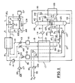
- the first embodiment of the invention is illustrated in the integrated combustion turbine/air separation system of Fig. 1.
- Fuel 1 is combined optionally with nitrogen 3 (later defined) and the combined stream 5 is combusted with compressed air 7 in combustor 101.
- Fuel 1 is preferably natural gas or synthesis gas produced by the gasification of carbonaceous material, but other gaseous fuels or liquid fuels may be used.
- Compressed air 7 is provided by compressor 105 at a pressure greater than 150 psia (1 MPa), preferably 240 to 440 psia (1.65 to 3.05 MPa).
- Hot combustion gas 9 at 2000 to 2600°F (1090 to 1430°C) and 240 to 440 psia (1.65 to 3.05 MPa) is expanded through hot gas expander 103 to generate shaft work which drives compressor 105 and optionally electric generator 107.
- the integrated combustor 101, hot gas expander 103, and compressor 105 is defined herein as combustion turbine 109.
- High pressure combustion turbine 109 is typical of new commercially-available systems such as the G and H series manufactured by General Electric and the GT 24/26 made by ABB.
- Extracted air Compressed air 11, hereinafter “extracted air” is withdrawn as a portion of compressed air 6 from compressor 105 at a temperature above 600°F (315°C). Extracted air 11 is cooled against nitrogen 13 (later defined) in heat exchanger 111, cooled air 14 is further cooled in cooler 113 and treated in purification system 115 to remove water, carbon dioxide, and other components which could freeze at cryogenic temperatures.
- Purification system 115 is preferably a temperature swing and/or pressure swing adsorption system of a type known in the art.
- Purified air 15 is cooled in heat exchanger 117 against cold process streams (later defined), a portion 17 is withdrawn at a temperature of -150 to -200°F (-100 to -130°C), and work expanded in expander 118. Cooled air 19 is introduced into lower pressure distillation column 119 at a temperature between -275 and -290°F (-170 and -180°C) and a pressure between 50 and 100 psia (345 and 690 kPa).
- the remaining purified air 21 is further cooled and typically is at least partially condensed, cooled air 22 is reduced in pressure across throttling valve 121, and the resulting air stream 23 at a temperature between -240 and -260°F (-150 and -165°C) and a pressure between 150 and 275 psia (1 MPa and 1.9 MPa) is introduced into higher pressure distillation column 123.
- cooled air 22 is fully condensed.
- the pressure of cooled air 22 alternatively can be reduced in an expansion turbine.
- Higher pressure distillation column 123 preferably operates at an absolute pressure of 20% to 85% of the absolute pressure of extracted air 11 from combustion turbine air compressor 105.
- Lower pressure column 119 and higher pressure column 123 are thermally integrated by reboiler-condenser 125 in the well-known double column distillation system for cryogenic air separation. If extracted air 11 does not provide sufficient air feed to the double column distillation system, supplemental air is provided by compressing air 25 in main air compressor 127, cooling and purifying the compressed air in cooler 129 and purification system 131 respectively, and further cooling the purified air 26 in heat exchanger 117.
- Purification system 131 is preferably a temperature swing and/or pressure swing adsorption system of a type known in the art. Cooled air 27 is introduced at or near the bottom of higher pressure column 123.
- cold recycled nitrogen-rich stream 29 (later defined) is reduced in pressure across throttling valve 133 to produce additional refrigeration and cooled expanded nitrogen-rich stream 31 is introduced into higher pressure column 123.
- Crude liquid oxygen 33 is cooled in heat exchanger 135 against cold nitrogen 35 (later defined), reduced in pressure across throttling valve 137, and introduced into lower pressure column 119.
- Nitrogen-rich liquid 37 is withdrawn at an intermediate point from higher pressure column 123, cooled in heat exchanger 135, reduced in pressure across throttling valve 139, and the reduced pressure nitrogen-rich stream 40 introduced at the top of lower pressure column 119 as reflux.
- Cold nitrogen 35 typically containing 0.1 to 4.0 mole % oxygen, is withdrawn at the top of lower pressure column 119, warmed in heat exchanger 135, and warmed further in heat exchanger 117 thereby providing refrigeration for cooling air feed streams 15 and 26.
- Warmed nitrogen 39 preferably is compressed in compressor 141, and a portion 13 of the resulting compressed nitrogen 12 is warmed in heat exchanger 111 against extracted compressed air 11.
- the resulting nitrogen 3 is introduced into combustor 101 in combination with fuel 1.
- the return of nitrogen 3 to combustor 101 is a preferred mode of operation which reduces the formation of nitrogen oxides during combustion and allows the most efficient operation of the integrated combustion turbine and cryogenic air separation systems.
- warmed nitrogen 39 can be used for another purpose rather than returned to combustor 101; this option could be utilized for example if fuel 1 were moisturized low BTU synthesis gas from a coal gasification system.
- a portion 41 of the nitrogen from compressor 141 is cooled in cooler 143 and the cooled portion 42 further cooled against warming streams in heat exchanger 117 to provide cold recycled nitrogen-rich stream 29 which is throttled and introduced into higher pressure column 123 as earlier described.
- High purity nitrogen 43 containing less than 0.2 mole % oxygen is withdrawn from higher pressure distillation column 123 and condensed in reboiler-condenser 125 against boiling liquid oxygen in the bottom of lower pressure column 119. A portion of the resulting liquid nitrogen provides reflux to higher pressure column 123 and the remaining liquid nitrogen 45 is optionally pumped to a pressure of 50 to 490 psia (0.35 to 3.4 MPa) by pump 145. Pressurized liquid nitrogen 47 is warmed and vaporized against cooling streams in heat exchanger 117 to provide high pressure nitrogen product 49.
- liquid nitrogen 45 is pumped to a supercritical pressure by pump 145, and supercritical fluid 47 is warmed in heat exchanger 117 to provide high pressure nitrogen product 49 at 490 psia (3.4 MPa) or above.
- Liquid oxygen 51 containing less than 15 mole % nitrogen is withdrawn from the bottom of lower pressure column 119 and optionally pumped to a pressure of 80 to 250 psia (0.55 to 1.7 MPa) in pump 147.
- Pressurized liquid oxygen 53 is warmed and vaporized against cooling streams in heat exchanger 117 to yield gaseous oxygen product 54 which optionally is compressed to 120 to 2000 psia (0.85 to 14 MPa) in compressor 149 to provide high pressure oxygen product 55.
- the alternative to withdrawing and pumping liquid nitrogen 45 is to withdraw nitrogen as vapor and/or liquid from the top of higher pressure column 123, as stream 45 or as a portion of vapor stream 43, and warm the withdrawn stream in heat exchanger 117.
- a nitrogen product compressor (not shown) would be needed to provide a high pressure nitrogen product equivalent to nitrogen product 49 in Fig. 1.
- oxygen is withdrawn as a vapor from the bottom of the lower pressure column (not shown) and the withdrawn vapor is warmed in heat exchanger 117 and compressed if necessary in compressor 149.
- compressor 149 would require more stages and consume more power to provide high pressure oxygen product 55 than in the earlier described mode in which liquid oxygen is withdrawn and pressurized by pump 147 before vaporization.
- a preferred embodiment of the invention utilizes the optional pumping of both liquid oxygen and liquid nitrogen as described above. Pumping the liquid products has the advantage of eliminating or reducing warm product compression, which in certain cases will reduce the total air separation power consumption, and the advantage of maintaining improved operating stability compared to full product compression.
- cooled air 22 is partially condensed and it is desirable to separate the two-phase stream into vapor and liquid before expansion.
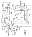
- This alternative is shown in Fig. 2; as in the embodiment of Fig. 1, a portion 17 of cooled and purified air 15 is work expanded in expander 118 and the resulting expanded cooled stream 19 is fed to lower pressure column 119. The remainder 21, however, is only partially condensed in heat exchanger 117 and the resulting two-phase stream 22 is separated in separator 203. Liquid 205 is reduced in pressure across throttling valve 207.
- Vapor 209 is warmed slightly, work-expanded in expander 211, the resulting cooled work-expanded stream 213 is combined with the reduced-pressure stream from throttling valve 207, and the combined stream 215 is introduced into higher pressure column 123.
- This alternative is useful when the flow rate of purified air 15 varies significantly and/or periodically over time.
- This embodiment is particularly useful in a gasification combined cycle (GCC) power generation system in which oxygen product 55 is used in a coal gasification system to produce fuel to operate combustion turbine system 109.
- GCC gasification combined cycle
- the available flow of extracted air 11 typically is reduced during periods of increased demand for power from electric generator 107 and during periods of increased ambient temperature.
- stream 22 would be fully condensed and no vapor 209 would be available to expander 211, and therefore this expander would not be operated.
- the available flow of extracted air 11 increases during periods of decreased demand for power from electric generator 107 and/or during periods of decreased ambient temperature.
- stream 22 would be partially condensed and vapor 209 would be work expanded in expander 211, thereby yielding additional refrigeration for higher pressure column 123. This in turn allows increased production of liquid products as described below.
- the option to operate expander 211 during periods of increased availability of extracted air 11 is an important feature of the invention, and preferably is utilized with the additional features of the embodiment illustrated in Fig. 3.
- air stream 22 is only partially condensed and vapor 209 is work expanded in expander 211 as earlier described.
- the resulting increased refrigeration allows the storage of liquid oxygen, which is withdrawn as liquid stream 51 and pumped by pump 147 to yield pressurized liquid oxygen 53. A portion 301 of this liquid is withdrawn and stored in storage vessel 303.
- liquid oxygen 305 is withdrawn from storage vessel 303, reduced in pressure across valve 307, and the reduced pressure liquid oxygen 308 introduced into the suction of pump 147. A portion of liquid oxygen 305 can be withdrawn as a liquid product if desired (not shown).
- expander 211 is not operated; in addition, operation of expander 118 may not be needed, and all air feed to the air separation system would be provided by streams 27 and 215.
- liquid nitrogen 38 is withdrawn and stored in storage vessel 317.
- crude liquid nitrogen is withdrawn from storage vessel 317, throttled across valve 319, and reduced-pressure liquid 321 is combined with liquid nitrogen from throttling valve 139, and the combined nitrogen stream is introduced into lower pressure column 119.
- This additional nitrogen supplied to lower pressure column 119 enables the withdrawal of additional nitrogen 35 from lower pressure column 119 thereby yielding an increased flow of return nitrogen 13.
- This alternative is particularly useful if the air separation system is sized for nitrogen production rather than oxygen production.
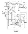
- FIG. 4 An alternative embodiment of the invention is illustrated in Fig. 4 wherein a portion 401 of cooled extracted air 412 from heat exchanger 111 is work expanded in expander 403, the expanded stream 404 is further cooled in cooler 129, and treated in purification system 131 to remove water, carbon dioxide, and other components which could freeze out at cryogenic temperatures.
- Purified air 26 is further cooled against warming streams in heat exchanger 117, and purified cooled air stream 27 is introduced into higher pressure distillation column 123.
- the remaining portion 14 of extracted air 412 provides feed to distillation columns 119 and 123 as earlier described.
- This alternative embodiment is similar to the embodiment of Fig. 1 except that the air to cooler 129 is provided by expanded extracted air from expander 403 (Fig. 4) rather than by air from main air compressor 127 (Fig. 1).
- Expansion turbine 403 is coupled with and drives compressor 405 which compresses return nitrogen 36 to an intermediate pressure of 100 to 200 psia (0.7 to 1.4 MPa), which is further compressed in compressor 407 to yield compressed return nitrogen 13 which is warmed in heat exchanger 111, the warmed return nitrogen 3 combined with fuel 1, and introduced into combustor 101 as previously described.
- Interstage nitrogen stream 409 is withdrawn from compressor 407, cooled in cooler 143 and the cooled stream 42 further cooled in heat exchanger 117, and reduced in pressure across throttling valve 133 to provide cold nitrogen recycle stream 31 to higher pressure distillation column 123. This in turn yields a higher purity in nitrogen product stream 45 withdrawn from higher pressure column 123.
- This embodiment is similar to the embodiments of Figs.
- expander 403 which operates compressor 405.
- This embodiment of the invention is possible because of a key feature of the present invention, namely, that higher pressure distillation column 123 operates at a pressure below that of extracted air 412 or 401.
- expander 403 operates in combination with throttling valve 121 to provide feed air streams 23 and 27 to higher pressure distillation column 123.
- work recovered by expander 403 reduces the work of compression required for return nitrogen 13 and recycle nitrogen 409, so that the power consumed by compressor 407 of Fig. 4 is significantly less than that of compressor 141 in Fig. 1.
- supplemental air 501 is compressed by compressor 503 and the resulting supplemental compressed air 505 is combined with extracted air 412 prior to division into air feed streams 14 and 401.
- Compressor 503 in this case is preferably an adiabatic compressor, although an intercooled compressor can be used if desired.
- air 501 can be compressed to a lower pressure as stream 507 and combined with expanded air 404 from expander 403 prior to cooler 129.
- supplemental air is provided only to high pressure distillation column 123 as feed stream 27.
- FIG. 6 Another alternative mode is shown in Fig. 6 wherein air 501 is compressed by multistage compressor 601; interstage compressed air 603 is withdrawn at an intermediate pressure and combined with the discharge air stream 404 from expander 403. The combined air stream is processed as earlier described to provide air feed 27 to higher pressure distillation column 123. Additional compressed air 605 is withdrawn from the last stage of compressor 601 and combined with extracted air 14 to provide air feed 15 for cooling, expansion, and introduction into distillation columns 119 and 123 as earlier described.
- Compressor 601 can be either an adiabatic or an intercooled compressor.
- coolers 113, 129, and 143 are used to cool gas streams after compression. Cooling duty in these coolers is typically provided by indirect heat exchange with water. The heat recovered in the water discharged from these coolers can be used elsewhere in the combustion turbine/air separation process. Such uses include moisturization of return nitrogen 3 and/or fuel gas 1 prior to introduction into combustor 101, preheating boiler feedwater, and heating adsorber regeneration gas for gas purification systems 115 and 131.
- a process heat and material balance was prepared for the embodiment of the invention described in Fig. 1 in which extracted air 11 from high pressure combustion turbine 109 is available at 348 psia (2.40 MPa) and 750°F (400°C) which supplies purified air feed 15 at 338 psia (2.33 MPa).
- the ambient temperature is 95°F (35°C).
- Higher pressure distillation column 123 and lower pressure distillation column 119 operate at average pressures of 185 and 63 psia (1275 and 434 kPa) respectively.
- Liquid oxygen 51 is pumped to 152 psia (1.05 MPa), vaporized, and compressed to 743 psia (5.12 MPa) to yield oxygen product 55.
- Liquid nitrogen 45 is pumped to 998 psia (6.88 MPa) and vaporized to provide nitrogen product 49 at 991 psia (6.83 MPa).
- Return nitrogen 39 contains 0.86 mole % oxygen.
- Table 1 A stream summary of the heat and material balance is summarized in Table 1.
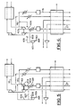
- Fig. 7 illustrates a double column air separation system which is integrated with a combustion turbine in a manner which utilizes several features known in the art.
- Combustion turbine 701 is identical to combustion turbine 109 of Fig. 1 and provides extracted air 703 at 348 psia (2.40 MPa).
- the extracted air is cooled in heat exchanger 704, the cooled extracted air 705 is expanded in expander 707, combined with supplemental compressed air 709 from compressor 700, cooled in cooler 711, and purified in purification system 723 to remove condensable contaminants.
- Purified air 713 at 190 psia (1.31 MPa) is further cooled in heat exchanger 725, and a portion 727 of cooled air 729 is work expanded in expander 731 and introduced directly into lower pressure distillation column 733. The remainder of the feed air is further cooled to yield cold feed air 735 which is introduced into higher pressure distillation column 737.
- Nitrogen 739 is withdrawn from lower pressure column 733, warmed in heat exchanger 741, the warmed stream 743 further warmed in heat exchanger 725, and the further warmed stream 745 compressed by compressor 747 to yield return nitrogen 749. A portion thereof is warmed against extracted air in heat exchanger 704 and the warmed stream 759 introduced into the combustor of combustion turbine 701.
- Fig. 3 The embodiment of Fig. 3 is operated in a gasification combined cycle power generation system through diurnal ambient temperature swings and variations in electric power demand.
- Oxygen 55 is used in a coal gasification system (not shown) to generate fuel 1.
- the ambient air temperature is lower and the demand for power from generator 107 is reduced.
- a nighttime temperature of 41°F (5°C) is assumed for a period of 10 hours, and at these conditions extracted air 11 at 343 psia (2.36 MPa) supplies 41.3% of the feed air required for the air separation system; the remainder is supplied by main air compressor 127.
- the air separation system produces 2000 tons/day (1800 tonnes/day) of contained oxygen 51 at a purity of 95 mole %.
- Oxygen gas 55 at 743 psia (5.12 MPa) containing 1960 tons/day (1780 tonnes/day) of oxygen is utilized in the coal gasification system (not shown), and the remaining 40 tons/day is stored in storage vessel 303 for 10 hours.
- a portion 17 of the extracted air is expanded in expander 118 and fed to lower pressure distillation column 119, and the remaining portion 22 is partially condensed and separated into liquid 205 and vapor 209.
- Liquid 205 is throttled into high pressure column 123; vapor 209 is partly warmed, expanded in expander 211, and fed to lower pressure distillation column 119.
- the refrigeration generated by expander 211 allows the condensation of additional liquid oxygen during nighttime operation for storage as described above.
- Liquid oxygen 51 is withdrawn at the rate of 1920 tons/day (1742 tonnes/day) from lower pressure column 119 and is supplemented by withdrawing stored liquid oxygen 305 at a rate of 80 tons/day (73 tonnes/day) to provide a total contained oxygen product 55 at a rate of 2000 tons/day (1800 tonnes/day).
- expanders 118 and 211 may be idled since the available amount of feed air 15 is decreased and the additional liquid oxygen vaporizing in heat exchanger 117 provides sufficient refrigeration. At these conditions, extracted air 15 is totally condensed and fed to higher pressure column 123 as a liquid feed 215.
- the relative power consumption of the air separation processes of Figs. 1 and 3 were calculated and are compared in Table 9 for operation at ambient air temperatures of 41°F (5°C) and 70°F (21°C) as described above. Relative power was calculated and normalized for each individual compressor and expander. The overall relative power consumptions were normalized based on the actual total power consumptions of the compressors and expanders. Since the daytime operation sets the required design capacity for main air compressor 127, the embodiment of Fig. 3 allows the use of a smaller compressor (5.4% lower design capacity) and the overall power consumption during daytime operation is thus reduced. It is seen from Table 9 that the use of nighttime oxygen storage of Fig. 3 results in reduced air separation power consumption during the two operating periods described above. The total overall average power calculated for a 24 hour period is 1.4% less using the liquid oxygen storage embodiment of Fig. 3 compared with operation without this feature as shown in Fig. 1.
- cryogenic liquids during periods of low power demand is essentially a form of energy storage.
- the use of this stored energy during periods of high power demand is especially advantageous because the value of electric power during such periods may be higher than the value during periods of low power demand.
- Table 9 Air Separation Relative Power Consumption (Example 2) 41°F (5°C) Ambient 70°F (21°C) Ambient Fig. 3 (Stored LOX) Fig. 3 (No Stored LOX) Fig. 3 (Stored LOX) Fig.
- FIG. 4 An embodiment of the invention is illustrated by the process of Fig. 4 without the use of liquid oxygen pump 147 and high pressure condensing air 22.
- all of extracted air 15 is cooled and expanded through expander 118 into lower pressure column 119.
- Higher pressure distillation column 123 is operated at an optimum feed pressure of about 245 psia (1.69 MPa), and oxygen product 55 is provided at 855 psia (5.90 MPa) by compressor 149.
- Gaseous nitrogen product 49 is provided at 1100 psia (7.58 MPa) by pumping liquid nitrogen 45 to a supercritical pressure and warming the resulting pressurized fluid 47 in heat exchanger 117.
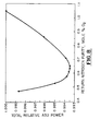
- Example 1 Mass and energy balances were calculated using the cycle and process conditions of Example 1 in which the oxygen concentration of return nitrogen 39 (Fig. 1) was varied from 0.48 to 1.05 mole % to determine the effect on the total relative power for the air separation process. The actual power at 1.05 mole % normalized and the total relative power at lower concentrations was determined on this basis.
- Fig. 8 illustrates the unexpected finding that the relative power passes through a minimum as a function of nitrogen purity.
- the process preferably is operated such that return nitrogen 39 contains between 0.5 and 0.8 mole % oxygen.
- This finding is highly unexpected because in typical combined cycle power plants the operators specify a maximum of 1 to 2 mole % oxygen in the return nitrogen purity, and it is generally believed that higher purity return nitrogen would require higher power consumption by the air separation system.
- a small increase in the flow of recycle nitrogen 41 to higher pressure column 123 has a significant effect on the purity of return nitrogen 39.
- Increasing the purity of return nitrogen 39 increases overall oxygen recovery and reduces the power of main air compressor 127 for a required production rate of oxygen product 55.
- the relative power according to Fig. 8 decreases as return nitrogen purity is reduced to an optimum of about 0.65 mole % oxygen.
- Mass and energy balances were calculated using the cycle and process conditions of Example 1 by varying the pressure of air feed 27 to higher pressure column 123 (Fig. 1) from 155 to 275 psia (1.07 to 1.90 MPa) to determine the effect of this pressure on the total power for the air separation process.
- the pressures of air feed 23 and recycle nitrogen 31 are adjusted accordingly.
- the total power was calculated at several selected air feed pressures in this range and unexpectedly a minimum in the power vs. feed pressure was found at about 245 psia (1.69 MPa).
- the calculated power values were normalized to the minimum value and the results are given in Fig. 9 which illustrates the unexpected finding that the relative power passes through a minimum as a function of higher pressure column air feed pressure.
- the process preferably is operated at an optimum feed pressure to the higher pressure column in the range of 190 to 280 psia (1.31 to 1.93 MPa).
- This finding differs from prior art combustion turbine-air separation cycles in which the optimum pressure of the higher pressure column occurs at much lower pressures; with the cycle of US-A-4,224,045, for example, this optimum occurs at about 150 psia (1.03 MPa).
- higher pressure distillation column 123 operates at a feed pressure significantly lower than the pressure of extracted air 11, preferably such that feed air 23 is introduced into higher pressure distillation column 123 at an absolute pressure which is 20% to 85% of the absolute pressure of extracted air 11 from combustion turbine air compressor 105.
- This important feature allows the air separation system to operate stably at constant pressures in which the pressure of higher pressure distillation column is below the minimum available pressure of extracted air 11 from combustion turbine compressor 105, which can vary considerably during part load operation of combustion turbine 109.
- constant pressure operation of the air separation system ensures that oxygen product compressor 149 and return nitrogen compressor 141 (or optionally return nitrogen compressors 405 and 407) operate at nearly constant suction pressure, which in turn allows the design of these compressors for narrower and more efficient ranges of operation.
- the purified extracted air 15 of the present invention is introduced into the air separation distillation columns by cooling the entire stream to an intermediate temperature, withdrawing a portion for work expansion into lower pressure column 119, and further cooling the remaining air for pressure reduction into higher pressure column 123.
- the pressure reduction of cooled purified feed air 22 into higher pressure column 123 is a unique feature of the present invention which allows independent control of the feed pressures to lower pressure column 119 and higher pressure column 123.
- the feed pressures to both columns can be operated below but otherwise independent of the pressure of extracted air 11.
- An important embodiment of the invention is the storage of selected cryogenic liquids during periods of low ambient temperature and/or low product demand.
- This embodiment preferably is utilized in conjunction with the pumping of liquid oxygen and/or liquid nitrogen before warming or vaporization to yield high pressure gas products.
- the combination of this embodiment with the key embodiment described above enables the highly efficient operation of an integrated air separation/combustion turbine system regardless of variability in the combustion turbine operation.
- the combination of these embodiments is particularly useful with new, high pressure combustion turbine systems which operate at compressor discharge pressures above 190 psia (1.3 MPa) and preferably in the range of 240 to 440 psia (1.65 to 3.01 MPa).
- the present invention is not limited to the use of a double column air separation process, and can be utilized in alternative cycles which operate at conditions of variable product demand and ambient temperature.
- the present invention could be applied to single column, dephlegmator, cold compression, and other types of air separation processes.
- the embodiments of the present invention also can be applied to air separation processes which use triple column distillation systems in which a third column is operated at a pressure intermediate the lower and higher pressure columns, for example such as those described in US-A-4,022,030, US-A-5,291,737, and US-A-5,231,837; pending U.S. Patent Application Serial No. 08/375,927, and EP-A-0636845.
Applications Claiming Priority (2)
| Application Number | Priority Date | Filing Date | Title |
|---|---|---|---|
| US08/595,015 US5666823A (en) | 1996-01-31 | 1996-01-31 | High pressure combustion turbine and air separation system integration |
| US595015 | 1996-01-31 |
Publications (2)
| Publication Number | Publication Date |
|---|---|
| EP0793070A2 true EP0793070A2 (fr) | 1997-09-03 |
| EP0793070A3 EP0793070A3 (fr) | 1998-08-05 |
Family
ID=24381358
Family Applications (1)
| Application Number | Title | Priority Date | Filing Date |
|---|---|---|---|
| EP97300573A Withdrawn EP0793070A3 (fr) | 1996-01-31 | 1997-01-29 | Intégration d'une turbine à combustion à haute température et d'un système de séparation d'air |
Country Status (7)
| Country | Link |
|---|---|
| US (1) | US5666823A (fr) |
| EP (1) | EP0793070A3 (fr) |
| JP (1) | JP3161696B2 (fr) |
| KR (1) | KR970059475A (fr) |
| CN (1) | CN1158941A (fr) |
| CA (1) | CA2195909A1 (fr) |
| TW (1) | TW358853B (fr) |
Cited By (8)
| Publication number | Priority date | Publication date | Assignee | Title |
|---|---|---|---|---|
| EP0924486A2 (fr) * | 1997-12-19 | 1999-06-23 | The BOC Group plc | Séparation d'air |
| EP0949471A1 (fr) * | 1998-04-08 | 1999-10-13 | Linde Aktiengesellschaft | Unité de séparation de l'air à deux modes de fonctionnement |
| FR2782787A1 (fr) * | 1998-08-28 | 2000-03-03 | Air Liquide | Procede et installation de production d'oxygene impur par distillation d'air |
| EP1053392A1 (fr) * | 1998-02-04 | 2000-11-22 | Texaco Development Corporation | Separation d'air cryogenique combinee avec une gazeification integree |
| EP1065458A1 (fr) * | 1999-06-28 | 2001-01-03 | Praxair Technology, Inc. | Système de rectification cryogénique pour la production d'oxygène à un débit variable |
| EP1120616A2 (fr) * | 2000-01-28 | 2001-08-01 | The BOC Group plc | Méthode de séparation de l'air |
| WO2014154361A2 (fr) * | 2013-03-28 | 2014-10-02 | Linde Aktiengesellschaft | Procédé et dispositif permettant de produire avec une consommation d'énergie variable de l'oxygène sous pression sous forme gazeuse |
| WO2014154339A2 (fr) | 2013-03-26 | 2014-10-02 | Linde Aktiengesellschaft | Procédé de séparation d'air et installation de séparation d'air |
Families Citing this family (52)
| Publication number | Priority date | Publication date | Assignee | Title |
|---|---|---|---|---|
| FR2753636B1 (fr) * | 1996-09-25 | 2001-11-09 | Air Liquide | Procede et installation pour l'alimentation pour un appareil de separation d'air |
| US6141950A (en) * | 1997-12-23 | 2000-11-07 | Air Products And Chemicals, Inc. | Integrated air separation and combustion turbine process with steam generation by indirect heat exchange with nitrogen |
| US6134916A (en) * | 1999-02-02 | 2000-10-24 | Texaco Inc. | Combined operation of a cryogenic air separation unit and an integrated gasifier combined cycle power generating system |
| US5979183A (en) * | 1998-05-22 | 1999-11-09 | Air Products And Chemicals, Inc. | High availability gas turbine drive for an air separation unit |
| DE19824766C2 (de) * | 1998-06-03 | 2000-05-11 | Siemens Ag | Gasturbine sowie Verfahren zur Kühlung einer Turbinenstufe |
| US5964085A (en) * | 1998-06-08 | 1999-10-12 | Siemens Westinghouse Power Corporation | System and method for generating a gaseous fuel from a solid fuel for use in a gas turbine based power plant |
| US6116027A (en) * | 1998-09-29 | 2000-09-12 | Air Products And Chemicals, Inc. | Supplemental air supply for an air separation system |
| US6202442B1 (en) * | 1999-04-05 | 2001-03-20 | L'air Liquide, Societe Anonyme Pour L'etude Et L'expoitation Des Procedes Georges Claude | Integrated apparatus for generating power and/or oxygen enriched fluid and process for the operation thereof |
| US6116052A (en) * | 1999-04-09 | 2000-09-12 | Air Liquide Process And Construction | Cryogenic air separation process and installation |
| US6347534B1 (en) | 1999-05-25 | 2002-02-19 | Air Liquide Process And Construction | Cryogenic distillation system for air separation |
| US6196024B1 (en) | 1999-05-25 | 2001-03-06 | L'air Liquide, Societe Anonyme Pour L'etude Et L'exploitation Des Procedes Georges Claude | Cryogenic distillation system for air separation |
| US6202441B1 (en) | 1999-05-25 | 2001-03-20 | Air Liquide Process And Construction, Inc. | Cryogenic distillation system for air separation |
| US6276170B1 (en) | 1999-05-25 | 2001-08-21 | Air Liquide Process And Construction | Cryogenic distillation system for air separation |
| US6345493B1 (en) | 1999-06-04 | 2002-02-12 | Air Products And Chemicals, Inc. | Air separation process and system with gas turbine drivers |
| US6256994B1 (en) | 1999-06-04 | 2001-07-10 | Air Products And Chemicals, Inc. | Operation of an air separation process with a combustion engine for the production of atmospheric gas products and electric power |
| US6263659B1 (en) | 1999-06-04 | 2001-07-24 | Air Products And Chemicals, Inc. | Air separation process integrated with gas turbine combustion engine driver |
| WO2001012754A1 (fr) * | 1999-08-19 | 2001-02-22 | Manufacturing And Technology Conversion International, Inc. | Turbine a gaz avec systeme de reformage a la vapeur chauffe indirectement |
| US6298652B1 (en) * | 1999-12-13 | 2001-10-09 | Exxon Mobil Chemical Patents Inc. | Method for utilizing gas reserves with low methane concentrations and high inert gas concentrations for fueling gas turbines |
| US6295838B1 (en) * | 2000-08-16 | 2001-10-02 | Praxair Technology, Inc. | Cryogenic air separation and gas turbine integration using heated nitrogen |
| US6295840B1 (en) | 2000-11-15 | 2001-10-02 | Air Products And Chemicals, Inc. | Pressurized liquid cryogen process |
| US7284362B2 (en) * | 2002-02-11 | 2007-10-23 | L'Air Liquide, Société Anonyme à Directoire et Conseil de Surveillance pour l'Étude et l'Exploitation des Procedes Georges Claude | Integrated air separation and oxygen fired power generation system |
| FR2858398B1 (fr) * | 2003-07-30 | 2005-12-02 | Air Liquide | Procede et installation d'alimentation d'une unite de separation d'air au moyen d'une turbine a gaz |
| ES2295945T3 (es) * | 2003-10-15 | 2008-04-16 | Ice Energy, Inc. | Sistema de almacenamiento de energia y de refrigeracion de alto rendimiento a base de un refrigerante. |
| US8234876B2 (en) * | 2003-10-15 | 2012-08-07 | Ice Energy, Inc. | Utility managed virtual power plant utilizing aggregated thermal energy storage |
| US7162878B2 (en) * | 2003-10-15 | 2007-01-16 | Ice Energy, Llc | Refrigeration apparatus |
| US7128005B2 (en) * | 2003-11-07 | 2006-10-31 | Carter Jr Greg | Non-polluting high temperature combustion system |
| US7228715B2 (en) | 2003-12-23 | 2007-06-12 | L'air Liquide, Societe Anonyme A Directoire Et Conseil De Surveillance Pour L'etude Et L'exploitation Des Procedes Georges Claude | Cryogenic air separation process and apparatus |
| US7197894B2 (en) * | 2004-02-13 | 2007-04-03 | L'air Liquide, Societe Anonyme A' Directorie Et Conseil De Survelliance Pour L'etude Et, L'exploltation Des Procedes Georges, Claude | Integrated process and air separation process |
| JP2006125255A (ja) * | 2004-10-27 | 2006-05-18 | Ebara Corp | ガスタービン装置およびガスタービン発電システム |
| US7549301B2 (en) * | 2006-06-09 | 2009-06-23 | Praxair Technology, Inc. | Air separation method |
| US8136369B2 (en) * | 2006-07-14 | 2012-03-20 | L'air Liquide Societe Anonyme Pour L'etude | System and apparatus for providing low pressure and low purity oxygen |
| US7921653B2 (en) * | 2007-11-26 | 2011-04-12 | General Electric Company | Internal manifold air extraction system for IGCC combustor and method |
| US8963347B2 (en) * | 2007-12-06 | 2015-02-24 | Sustainable Energy Solutions, Llc | Methods and systems for generating power from a turbine using pressurized nitrogen |
| GB0808200D0 (en) * | 2008-05-06 | 2008-06-11 | Invista Technologies Srl | Power recovery |
| US8063511B2 (en) * | 2008-05-27 | 2011-11-22 | Expansion Energy, Llc | System and method for liquid air production, power storage and power release |
| US7821158B2 (en) * | 2008-05-27 | 2010-10-26 | Expansion Energy, Llc | System and method for liquid air production, power storage and power release |
| CA2728244A1 (fr) * | 2008-06-19 | 2009-12-23 | William Brigham | Procede de separation d'air hybride a enrichissement preliminaire non cryogenique et purification cryogenique faisant appel a un generateur de gaz ou de liquide a un seul composant |
| FR2949846B1 (fr) * | 2009-09-10 | 2012-02-10 | Air Liquide | Procede et installation de production d'oxygene par distillation d'air |
| US9457313B2 (en) * | 2010-09-13 | 2016-10-04 | Membrane Technology And Research, Inc. | Membrane technology for use in a power generation process |
| US8726628B2 (en) * | 2010-10-22 | 2014-05-20 | General Electric Company | Combined cycle power plant including a carbon dioxide collection system |
| US20130000352A1 (en) * | 2011-06-30 | 2013-01-03 | General Electric Company | Air separation unit and systems incorporating the same |
| CN102809262B (zh) * | 2012-08-22 | 2015-08-26 | 杭州杭氧股份有限公司 | 一种利用igcc燃气轮机压缩空气生产氧气的方法及装置 |
| US20140130509A1 (en) * | 2012-11-13 | 2014-05-15 | Raymond Francis Drnevich | Combined gasification and power generation |
| US8907524B2 (en) | 2013-05-09 | 2014-12-09 | Expansion Energy Llc | Systems and methods of semi-centralized power storage and power production for multi-directional smart grid and other applications |
| US20150093656A1 (en) * | 2013-10-01 | 2015-04-02 | Scott Clair Pockrandt | Liquid nitrogen battery |
| EP3059536A1 (fr) * | 2015-02-19 | 2016-08-24 | Linde Aktiengesellschaft | Procédé et dispositif destinés à la production d'un produit d'azote pressurisé |
| JP6705771B2 (ja) * | 2017-04-21 | 2020-06-03 | 株式会社神戸製鋼所 | 圧縮空気貯蔵発電装置 |
| CN111527361B (zh) * | 2017-12-29 | 2022-03-04 | 乔治洛德方法研究和开发液化空气有限公司 | 一种基于深冷精馏生产空气产品的方法及设备 |
| EP3696486A1 (fr) * | 2019-02-13 | 2020-08-19 | Linde GmbH | Procédé et installation de fourniture d'un ou d'une pluralité de produits dérivés de l'air gazeux, riches en oxygène |
| CN113154796B (zh) * | 2021-03-23 | 2022-12-09 | 金川集团股份有限公司 | 一种回收氧氮资源的可变多循环氧氮冷能利用装置及方法 |
| CN113606869A (zh) * | 2021-08-20 | 2021-11-05 | 中国联合重型燃气轮机技术有限公司 | 用于igcc的空分系统、igcc和igcc的控制方法 |
| CN113606868A (zh) * | 2021-08-20 | 2021-11-05 | 中国联合重型燃气轮机技术有限公司 | Igcc、igcc的控制方法和用于igcc的空分系统 |
Citations (22)
| Publication number | Priority date | Publication date | Assignee | Title |
|---|---|---|---|---|
| US3731495A (en) | 1970-12-28 | 1973-05-08 | Union Carbide Corp | Process of and apparatus for air separation with nitrogen quenched power turbine |
| US4019314A (en) | 1975-01-27 | 1977-04-26 | Linde Aktiengesellschaft | High pressure gasification of coal using nitrogen dilution of waste gas from steam generator |
| US4022030A (en) | 1971-02-01 | 1977-05-10 | L'air Liquide, Societe Anonyme Pour L'etude Et L'exploitation Des Procedes Georges Claude | Thermal cycle for the compression of a fluid by the expansion of another fluid |
| US4224045A (en) | 1978-08-23 | 1980-09-23 | Union Carbide Corporation | Cryogenic system for producing low-purity oxygen |
| GB2067668A (en) | 1980-01-21 | 1981-07-30 | Gen Electric | Control of NOx emissions in a stationary gas turbine |
| US4557735A (en) | 1984-02-21 | 1985-12-10 | Union Carbide Corporation | Method for preparing air for separation by rectification |
| US4697415A (en) | 1985-08-05 | 1987-10-06 | Kraftwerk Union Aktiengesellschaft | Combined gas and steam-turbine power generating station |
| US5081845A (en) | 1990-07-02 | 1992-01-21 | Air Products And Chemicals, Inc. | Integrated air separation plant - integrated gasification combined cycle power generator |
| US5082482A (en) | 1989-10-09 | 1992-01-21 | L'air Liquide, Societe Anonyme Pour L'etude Et L'exploitation Des Procedes Georges Claude | Process and apparatus for the production of gaseous oxygen with a variable flow by air distillation |
| US5084081A (en) | 1989-04-27 | 1992-01-28 | Linde Aktiengesellschaft | Low temperature air fractionation accommodating variable oxygen demand |
| US5098457A (en) | 1991-01-22 | 1992-03-24 | Union Carbide Industrial Gases Technology Corporation | Method and apparatus for producing elevated pressure nitrogen |
| US5148680A (en) | 1990-06-27 | 1992-09-22 | Union Carbide Industrial Gases Technology Corporation | Cryogenic air separation system with dual product side condenser |
| US5224336A (en) | 1991-06-20 | 1993-07-06 | Air Products And Chemicals, Inc. | Process and system for controlling a cryogenic air separation unit during rapid changes in production |
| US5231837A (en) | 1991-10-15 | 1993-08-03 | Liquid Air Engineering Corporation | Cryogenic distillation process for the production of oxygen and nitrogen |
| US5291737A (en) | 1991-08-07 | 1994-03-08 | L'air Liquide, Societe Anonyme Pour L'etude Et L'exploitation Des Procedes Georges Claude | Process or apparatus for distilling air and application in feeding gas to a steel mill |
| US5303556A (en) | 1993-01-21 | 1994-04-19 | Praxair Technology, Inc. | Single column cryogenic rectification system for producing nitrogen gas at elevated pressure and high purity |
| US5355682A (en) | 1993-09-15 | 1994-10-18 | Air Products And Chemicals, Inc. | Cryogenic air separation process producing elevated pressure nitrogen by pumped liquid nitrogen |
| EP0636845A1 (fr) | 1993-04-30 | 1995-02-01 | The BOC Group plc | Séparation d air |
| US5386686A (en) | 1992-04-29 | 1995-02-07 | L'air Liquide, Societe Anonyme Pour L'etude Et L'exploitation Des Procedes Georges Claude | Process for the operation of a gas turbine group and the production of at least one air gas |
| US5406786A (en) | 1993-07-16 | 1995-04-18 | Air Products And Chemicals, Inc. | Integrated air separation - gas turbine electrical generation process |
| US5410869A (en) | 1993-01-18 | 1995-05-02 | Abb Management Ag | Method of operating a combination power plant by coal or oil gasification |
| US5459994A (en) | 1993-05-28 | 1995-10-24 | Praxair Technology, Inc. | Gas turbine-air separation plant combination |
Family Cites Families (4)
| Publication number | Priority date | Publication date | Assignee | Title |
|---|---|---|---|---|
| IL36741A (en) * | 1971-04-30 | 1974-11-29 | Zakon T | Method for the separation of gaseous mixtures with recuperation of mechanical energy and apparatus for carrying out this method |
| US4785621A (en) * | 1987-05-28 | 1988-11-22 | General Electric Company | Air bottoming cycle for coal gasification plant |
| GB9100814D0 (en) * | 1991-01-15 | 1991-02-27 | Boc Group Plc | Air separation |
| FR2704632B1 (fr) * | 1993-04-29 | 1995-06-23 | Air Liquide | Procede et installation pour la separation de l'air. |
-
1996
- 1996-01-31 US US08/595,015 patent/US5666823A/en not_active Expired - Fee Related
- 1996-08-26 TW TW085110352A patent/TW358853B/zh active
-
1997
- 1997-01-24 CA CA002195909A patent/CA2195909A1/fr not_active Abandoned
- 1997-01-29 EP EP97300573A patent/EP0793070A3/fr not_active Withdrawn
- 1997-01-29 KR KR1019970002558A patent/KR970059475A/ko active IP Right Grant
- 1997-01-30 JP JP01709297A patent/JP3161696B2/ja not_active Expired - Fee Related
- 1997-01-31 CN CN97101851A patent/CN1158941A/zh active Pending
Patent Citations (22)
| Publication number | Priority date | Publication date | Assignee | Title |
|---|---|---|---|---|
| US3731495A (en) | 1970-12-28 | 1973-05-08 | Union Carbide Corp | Process of and apparatus for air separation with nitrogen quenched power turbine |
| US4022030A (en) | 1971-02-01 | 1977-05-10 | L'air Liquide, Societe Anonyme Pour L'etude Et L'exploitation Des Procedes Georges Claude | Thermal cycle for the compression of a fluid by the expansion of another fluid |
| US4019314A (en) | 1975-01-27 | 1977-04-26 | Linde Aktiengesellschaft | High pressure gasification of coal using nitrogen dilution of waste gas from steam generator |
| US4224045A (en) | 1978-08-23 | 1980-09-23 | Union Carbide Corporation | Cryogenic system for producing low-purity oxygen |
| GB2067668A (en) | 1980-01-21 | 1981-07-30 | Gen Electric | Control of NOx emissions in a stationary gas turbine |
| US4557735A (en) | 1984-02-21 | 1985-12-10 | Union Carbide Corporation | Method for preparing air for separation by rectification |
| US4697415A (en) | 1985-08-05 | 1987-10-06 | Kraftwerk Union Aktiengesellschaft | Combined gas and steam-turbine power generating station |
| US5084081A (en) | 1989-04-27 | 1992-01-28 | Linde Aktiengesellschaft | Low temperature air fractionation accommodating variable oxygen demand |
| US5082482A (en) | 1989-10-09 | 1992-01-21 | L'air Liquide, Societe Anonyme Pour L'etude Et L'exploitation Des Procedes Georges Claude | Process and apparatus for the production of gaseous oxygen with a variable flow by air distillation |
| US5148680A (en) | 1990-06-27 | 1992-09-22 | Union Carbide Industrial Gases Technology Corporation | Cryogenic air separation system with dual product side condenser |
| US5081845A (en) | 1990-07-02 | 1992-01-21 | Air Products And Chemicals, Inc. | Integrated air separation plant - integrated gasification combined cycle power generator |
| US5098457A (en) | 1991-01-22 | 1992-03-24 | Union Carbide Industrial Gases Technology Corporation | Method and apparatus for producing elevated pressure nitrogen |
| US5224336A (en) | 1991-06-20 | 1993-07-06 | Air Products And Chemicals, Inc. | Process and system for controlling a cryogenic air separation unit during rapid changes in production |
| US5291737A (en) | 1991-08-07 | 1994-03-08 | L'air Liquide, Societe Anonyme Pour L'etude Et L'exploitation Des Procedes Georges Claude | Process or apparatus for distilling air and application in feeding gas to a steel mill |
| US5231837A (en) | 1991-10-15 | 1993-08-03 | Liquid Air Engineering Corporation | Cryogenic distillation process for the production of oxygen and nitrogen |
| US5386686A (en) | 1992-04-29 | 1995-02-07 | L'air Liquide, Societe Anonyme Pour L'etude Et L'exploitation Des Procedes Georges Claude | Process for the operation of a gas turbine group and the production of at least one air gas |
| US5410869A (en) | 1993-01-18 | 1995-05-02 | Abb Management Ag | Method of operating a combination power plant by coal or oil gasification |
| US5303556A (en) | 1993-01-21 | 1994-04-19 | Praxair Technology, Inc. | Single column cryogenic rectification system for producing nitrogen gas at elevated pressure and high purity |
| EP0636845A1 (fr) | 1993-04-30 | 1995-02-01 | The BOC Group plc | Séparation d air |
| US5459994A (en) | 1993-05-28 | 1995-10-24 | Praxair Technology, Inc. | Gas turbine-air separation plant combination |
| US5406786A (en) | 1993-07-16 | 1995-04-18 | Air Products And Chemicals, Inc. | Integrated air separation - gas turbine electrical generation process |
| US5355682A (en) | 1993-09-15 | 1994-10-18 | Air Products And Chemicals, Inc. | Cryogenic air separation process producing elevated pressure nitrogen by pumped liquid nitrogen |
Non-Patent Citations (4)
Cited By (18)
| Publication number | Priority date | Publication date | Assignee | Title |
|---|---|---|---|---|
| EP0924486A3 (fr) * | 1997-12-19 | 1999-09-29 | The BOC Group plc | Séparation d'air |
| EP0924486A2 (fr) * | 1997-12-19 | 1999-06-23 | The BOC Group plc | Séparation d'air |
| US6141989A (en) * | 1997-12-19 | 2000-11-07 | The Boc Group Plc | Air separation |
| EP1053392A1 (fr) * | 1998-02-04 | 2000-11-22 | Texaco Development Corporation | Separation d'air cryogenique combinee avec une gazeification integree |
| EP1053392A4 (fr) * | 1998-02-04 | 2003-05-28 | Texaco Development Corp | Separation d'air cryogenique combinee avec une gazeification integree |
| CZ297724B6 (cs) * | 1998-04-08 | 2007-03-14 | Linde Ag | Zpusob výroby plynného tlakového produktu, zarízení k provádení tohoto zpusobu a pouzití tohoto zpusobu a zarízení |
| US6185960B1 (en) | 1998-04-08 | 2001-02-13 | Linde Aktiengesellschaft | Process and device for the production of a pressurized gaseous product by low-temperature separation of air |
| EP0949471A1 (fr) * | 1998-04-08 | 1999-10-13 | Linde Aktiengesellschaft | Unité de séparation de l'air à deux modes de fonctionnement |
| US6247333B1 (en) | 1998-08-28 | 2001-06-19 | L'air Liquide, Societe Anonyme Pour L'etrude Et L'exploitation Des Procedes Georges Claude | Process for supplying impure oxygen to a synthesis-gas production unit |
| FR2782787A1 (fr) * | 1998-08-28 | 2000-03-03 | Air Liquide | Procede et installation de production d'oxygene impur par distillation d'air |
| EP1065458A1 (fr) * | 1999-06-28 | 2001-01-03 | Praxair Technology, Inc. | Système de rectification cryogénique pour la production d'oxygène à un débit variable |
| EP1120616A2 (fr) * | 2000-01-28 | 2001-08-01 | The BOC Group plc | Méthode de séparation de l'air |
| EP1120616A3 (fr) * | 2000-01-28 | 2002-08-28 | The BOC Group plc | Méthode de séparation de l'air |
| WO2014154339A2 (fr) | 2013-03-26 | 2014-10-02 | Linde Aktiengesellschaft | Procédé de séparation d'air et installation de séparation d'air |
| WO2014154339A3 (fr) * | 2013-03-26 | 2015-01-08 | Linde Aktiengesellschaft | Procédé de séparation d'air et installation de séparation d'air |
| WO2014154361A2 (fr) * | 2013-03-28 | 2014-10-02 | Linde Aktiengesellschaft | Procédé et dispositif permettant de produire avec une consommation d'énergie variable de l'oxygène sous pression sous forme gazeuse |
| WO2014154361A3 (fr) * | 2013-03-28 | 2014-12-11 | Linde Aktiengesellschaft | Procédé et dispositif permettant de produire avec une consommation d'énergie variable de l'oxygène sous pression sous forme gazeuse |
| CN105143801A (zh) * | 2013-03-28 | 2015-12-09 | 林德股份公司 | 以可变能量消耗产生气态压缩氧的方法和设备 |
Also Published As
| Publication number | Publication date |
|---|---|
| EP0793070A3 (fr) | 1998-08-05 |
| JP3161696B2 (ja) | 2001-04-25 |
| TW358853B (en) | 1999-05-21 |
| CA2195909A1 (fr) | 1997-08-01 |
| US5666823A (en) | 1997-09-16 |
| CN1158941A (zh) | 1997-09-10 |
| KR970059475A (ko) | 1997-08-12 |
| JPH09228852A (ja) | 1997-09-02 |
Similar Documents
| Publication | Publication Date | Title |
|---|---|---|
| EP0793070A2 (fr) | Intégration d'une turbine à combustion à haute température et d'un système de séparation d'air | |
| US5722259A (en) | Combustion turbine and elevated pressure air separation system with argon recovery | |
| US5081845A (en) | Integrated air separation plant - integrated gasification combined cycle power generator | |
| CA2082673C (fr) | Cycles de separation d'air a pression elevee dans une installation a rebouilleur multiple a colonne double, et leur integration dans des turbomachines | |
| JP2758355B2 (ja) | 酸素と加圧窒素を製造するための低温空気分離方法 | |
| EP0584419B1 (fr) | Procédé et installation de distillation d'air | |
| US20140260422A1 (en) | Low Temperature Air Separation Process for Producing Pressurized Gaseous Product | |
| AU630837B1 (en) | Elevated pressure air separation cycles with liquid production | |
| JPH07159026A (ja) | 酸素と窒素を気体及び/又は液体製品として同時に製造するための空気の低温蒸留法 | |
| CN110678710B (zh) | 用于通过低温蒸馏分离空气的方法和设备 | |
| US5412953A (en) | Process and installation for the production of gaseous oxygen and/or gaseous nitrogen under pressure by distillation of air | |
| US6009723A (en) | Elevated pressure air separation process with use of waste expansion for compression of a process stream | |
| EP0584420B1 (fr) | Cycle de séparation d'air à colonne unique et son intégration dans des turbines à gaz | |
| CN1233740A (zh) | 制备氧的单膨胀器和冷压缩机法 | |
| WO2014053297A2 (fr) | Processus de séparation de l'air par distillation cryogénique | |
| US6718794B2 (en) | Method and apparatus for generating energy | |
| US6116052A (en) | Cryogenic air separation process and installation | |
| Smith et al. | Next-generation integration concepts for air separation units and gas turbines | |
| US6357259B1 (en) | Air separation method to produce gaseous product | |
| US4947649A (en) | Cryogenic process for producing low-purity oxygen | |
| US7219514B2 (en) | Method for separating air by cryogenic distillation and installation therefor | |
| EP2741036A1 (fr) | Processus et appareil pour la séparation de l'air par distillation cryogénique | |
| Smith et al. | Next-generation integration concepts for air separation units and gas turbines | |
| Smith et al. | Air separation unit integration for alternative fuel projects | |
| AU649907B2 (en) | Integrated air separation plant - integrated gasification combined cycle power generator |
Legal Events
| Date | Code | Title | Description |
|---|---|---|---|
| PUAI | Public reference made under article 153(3) epc to a published international application that has entered the european phase |
Free format text: ORIGINAL CODE: 0009012 |
|
| AK | Designated contracting states |
Kind code of ref document: A2 Designated state(s): BE DE DK ES FI FR GB IT NL SE |
|
| PUAL | Search report despatched |
Free format text: ORIGINAL CODE: 0009013 |
|
| AK | Designated contracting states |
Kind code of ref document: A3 Designated state(s): BE DE DK ES FI FR GB IT NL SE |
|
| 17P | Request for examination filed |
Effective date: 19981214 |
|
| 17Q | First examination report despatched |
Effective date: 20000824 |
|
| STAA | Information on the status of an ep patent application or granted ep patent |
Free format text: STATUS: THE APPLICATION IS DEEMED TO BE WITHDRAWN |
|
| 18D | Application deemed to be withdrawn |
Effective date: 20020619 |