EP0454327B2 - Séparation d'air - Google Patents
Séparation d'air Download PDFInfo
- Publication number
- EP0454327B2 EP0454327B2 EP91303237A EP91303237A EP0454327B2 EP 0454327 B2 EP0454327 B2 EP 0454327B2 EP 91303237 A EP91303237 A EP 91303237A EP 91303237 A EP91303237 A EP 91303237A EP 0454327 B2 EP0454327 B2 EP 0454327B2
- Authority
- EP
- European Patent Office
- Prior art keywords
- pressure stage
- expansion
- air
- stream
- column
- Prior art date
- Legal status (The legal status is an assumption and is not a legal conclusion. Google has not performed a legal analysis and makes no representation as to the accuracy of the status listed.)
- Expired - Lifetime
Links
Images


Classifications
-
- F—MECHANICAL ENGINEERING; LIGHTING; HEATING; WEAPONS; BLASTING
- F25—REFRIGERATION OR COOLING; COMBINED HEATING AND REFRIGERATION SYSTEMS; HEAT PUMP SYSTEMS; MANUFACTURE OR STORAGE OF ICE; LIQUEFACTION SOLIDIFICATION OF GASES
- F25J—LIQUEFACTION, SOLIDIFICATION OR SEPARATION OF GASES OR GASEOUS OR LIQUEFIED GASEOUS MIXTURES BY PRESSURE AND COLD TREATMENT OR BY BRINGING THEM INTO THE SUPERCRITICAL STATE
- F25J3/00—Processes or apparatus for separating the constituents of gaseous or liquefied gaseous mixtures involving the use of liquefaction or solidification
- F25J3/02—Processes or apparatus for separating the constituents of gaseous or liquefied gaseous mixtures involving the use of liquefaction or solidification by rectification, i.e. by continuous interchange of heat and material between a vapour stream and a liquid stream
- F25J3/04—Processes or apparatus for separating the constituents of gaseous or liquefied gaseous mixtures involving the use of liquefaction or solidification by rectification, i.e. by continuous interchange of heat and material between a vapour stream and a liquid stream for air
- F25J3/04151—Purification and (pre-)cooling of the feed air; recuperative heat-exchange with product streams
- F25J3/04187—Cooling of the purified feed air by recuperative heat-exchange; Heat-exchange with product streams
- F25J3/04193—Division of the main heat exchange line in consecutive sections having different functions
- F25J3/042—Division of the main heat exchange line in consecutive sections having different functions having an intermediate feed connection
-
- F—MECHANICAL ENGINEERING; LIGHTING; HEATING; WEAPONS; BLASTING
- F25—REFRIGERATION OR COOLING; COMBINED HEATING AND REFRIGERATION SYSTEMS; HEAT PUMP SYSTEMS; MANUFACTURE OR STORAGE OF ICE; LIQUEFACTION SOLIDIFICATION OF GASES
- F25J—LIQUEFACTION, SOLIDIFICATION OR SEPARATION OF GASES OR GASEOUS OR LIQUEFIED GASEOUS MIXTURES BY PRESSURE AND COLD TREATMENT OR BY BRINGING THEM INTO THE SUPERCRITICAL STATE
- F25J3/00—Processes or apparatus for separating the constituents of gaseous or liquefied gaseous mixtures involving the use of liquefaction or solidification
- F25J3/02—Processes or apparatus for separating the constituents of gaseous or liquefied gaseous mixtures involving the use of liquefaction or solidification by rectification, i.e. by continuous interchange of heat and material between a vapour stream and a liquid stream
- F25J3/04—Processes or apparatus for separating the constituents of gaseous or liquefied gaseous mixtures involving the use of liquefaction or solidification by rectification, i.e. by continuous interchange of heat and material between a vapour stream and a liquid stream for air
- F25J3/04248—Generation of cold for compensating heat leaks or liquid production, e.g. by Joule-Thompson expansion
- F25J3/04284—Generation of cold for compensating heat leaks or liquid production, e.g. by Joule-Thompson expansion using internal refrigeration by open-loop gas work expansion, e.g. of intermediate or oxygen enriched (waste-)streams
- F25J3/0429—Generation of cold for compensating heat leaks or liquid production, e.g. by Joule-Thompson expansion using internal refrigeration by open-loop gas work expansion, e.g. of intermediate or oxygen enriched (waste-)streams of feed air, e.g. used as waste or product air or expanded into an auxiliary column
- F25J3/04303—Lachmann expansion, i.e. expanded into oxygen producing or low pressure column
-
- F—MECHANICAL ENGINEERING; LIGHTING; HEATING; WEAPONS; BLASTING
- F25—REFRIGERATION OR COOLING; COMBINED HEATING AND REFRIGERATION SYSTEMS; HEAT PUMP SYSTEMS; MANUFACTURE OR STORAGE OF ICE; LIQUEFACTION SOLIDIFICATION OF GASES
- F25J—LIQUEFACTION, SOLIDIFICATION OR SEPARATION OF GASES OR GASEOUS OR LIQUEFIED GASEOUS MIXTURES BY PRESSURE AND COLD TREATMENT OR BY BRINGING THEM INTO THE SUPERCRITICAL STATE
- F25J3/00—Processes or apparatus for separating the constituents of gaseous or liquefied gaseous mixtures involving the use of liquefaction or solidification
- F25J3/02—Processes or apparatus for separating the constituents of gaseous or liquefied gaseous mixtures involving the use of liquefaction or solidification by rectification, i.e. by continuous interchange of heat and material between a vapour stream and a liquid stream
- F25J3/04—Processes or apparatus for separating the constituents of gaseous or liquefied gaseous mixtures involving the use of liquefaction or solidification by rectification, i.e. by continuous interchange of heat and material between a vapour stream and a liquid stream for air
- F25J3/04248—Generation of cold for compensating heat leaks or liquid production, e.g. by Joule-Thompson expansion
- F25J3/04284—Generation of cold for compensating heat leaks or liquid production, e.g. by Joule-Thompson expansion using internal refrigeration by open-loop gas work expansion, e.g. of intermediate or oxygen enriched (waste-)streams
- F25J3/04309—Generation of cold for compensating heat leaks or liquid production, e.g. by Joule-Thompson expansion using internal refrigeration by open-loop gas work expansion, e.g. of intermediate or oxygen enriched (waste-)streams of nitrogen
-
- F—MECHANICAL ENGINEERING; LIGHTING; HEATING; WEAPONS; BLASTING
- F25—REFRIGERATION OR COOLING; COMBINED HEATING AND REFRIGERATION SYSTEMS; HEAT PUMP SYSTEMS; MANUFACTURE OR STORAGE OF ICE; LIQUEFACTION SOLIDIFICATION OF GASES
- F25J—LIQUEFACTION, SOLIDIFICATION OR SEPARATION OF GASES OR GASEOUS OR LIQUEFIED GASEOUS MIXTURES BY PRESSURE AND COLD TREATMENT OR BY BRINGING THEM INTO THE SUPERCRITICAL STATE
- F25J3/00—Processes or apparatus for separating the constituents of gaseous or liquefied gaseous mixtures involving the use of liquefaction or solidification
- F25J3/02—Processes or apparatus for separating the constituents of gaseous or liquefied gaseous mixtures involving the use of liquefaction or solidification by rectification, i.e. by continuous interchange of heat and material between a vapour stream and a liquid stream
- F25J3/04—Processes or apparatus for separating the constituents of gaseous or liquefied gaseous mixtures involving the use of liquefaction or solidification by rectification, i.e. by continuous interchange of heat and material between a vapour stream and a liquid stream for air
- F25J3/04248—Generation of cold for compensating heat leaks or liquid production, e.g. by Joule-Thompson expansion
- F25J3/04375—Details relating to the work expansion, e.g. process parameter etc.
- F25J3/04393—Details relating to the work expansion, e.g. process parameter etc. using multiple or multistage gas work expansion
-
- F—MECHANICAL ENGINEERING; LIGHTING; HEATING; WEAPONS; BLASTING
- F25—REFRIGERATION OR COOLING; COMBINED HEATING AND REFRIGERATION SYSTEMS; HEAT PUMP SYSTEMS; MANUFACTURE OR STORAGE OF ICE; LIQUEFACTION SOLIDIFICATION OF GASES
- F25J—LIQUEFACTION, SOLIDIFICATION OR SEPARATION OF GASES OR GASEOUS OR LIQUEFIED GASEOUS MIXTURES BY PRESSURE AND COLD TREATMENT OR BY BRINGING THEM INTO THE SUPERCRITICAL STATE
- F25J3/00—Processes or apparatus for separating the constituents of gaseous or liquefied gaseous mixtures involving the use of liquefaction or solidification
- F25J3/02—Processes or apparatus for separating the constituents of gaseous or liquefied gaseous mixtures involving the use of liquefaction or solidification by rectification, i.e. by continuous interchange of heat and material between a vapour stream and a liquid stream
- F25J3/04—Processes or apparatus for separating the constituents of gaseous or liquefied gaseous mixtures involving the use of liquefaction or solidification by rectification, i.e. by continuous interchange of heat and material between a vapour stream and a liquid stream for air
- F25J3/04406—Processes or apparatus for separating the constituents of gaseous or liquefied gaseous mixtures involving the use of liquefaction or solidification by rectification, i.e. by continuous interchange of heat and material between a vapour stream and a liquid stream for air using a dual pressure main column system
- F25J3/04412—Processes or apparatus for separating the constituents of gaseous or liquefied gaseous mixtures involving the use of liquefaction or solidification by rectification, i.e. by continuous interchange of heat and material between a vapour stream and a liquid stream for air using a dual pressure main column system in a classical double column flowsheet, i.e. with thermal coupling by a main reboiler-condenser in the bottom of low pressure respectively top of high pressure column
-
- F—MECHANICAL ENGINEERING; LIGHTING; HEATING; WEAPONS; BLASTING
- F25—REFRIGERATION OR COOLING; COMBINED HEATING AND REFRIGERATION SYSTEMS; HEAT PUMP SYSTEMS; MANUFACTURE OR STORAGE OF ICE; LIQUEFACTION SOLIDIFICATION OF GASES
- F25J—LIQUEFACTION, SOLIDIFICATION OR SEPARATION OF GASES OR GASEOUS OR LIQUEFIED GASEOUS MIXTURES BY PRESSURE AND COLD TREATMENT OR BY BRINGING THEM INTO THE SUPERCRITICAL STATE
- F25J3/00—Processes or apparatus for separating the constituents of gaseous or liquefied gaseous mixtures involving the use of liquefaction or solidification
- F25J3/02—Processes or apparatus for separating the constituents of gaseous or liquefied gaseous mixtures involving the use of liquefaction or solidification by rectification, i.e. by continuous interchange of heat and material between a vapour stream and a liquid stream
- F25J3/04—Processes or apparatus for separating the constituents of gaseous or liquefied gaseous mixtures involving the use of liquefaction or solidification by rectification, i.e. by continuous interchange of heat and material between a vapour stream and a liquid stream for air
- F25J3/04642—Recovering noble gases from air
- F25J3/04648—Recovering noble gases from air argon
- F25J3/04654—Producing crude argon in a crude argon column
- F25J3/04666—Producing crude argon in a crude argon column as a parallel working rectification column of the low pressure column in a dual pressure main column system
- F25J3/04672—Producing crude argon in a crude argon column as a parallel working rectification column of the low pressure column in a dual pressure main column system having a top condenser
- F25J3/04678—Producing crude argon in a crude argon column as a parallel working rectification column of the low pressure column in a dual pressure main column system having a top condenser cooled by oxygen enriched liquid from high pressure column bottoms
-
- F—MECHANICAL ENGINEERING; LIGHTING; HEATING; WEAPONS; BLASTING
- F25—REFRIGERATION OR COOLING; COMBINED HEATING AND REFRIGERATION SYSTEMS; HEAT PUMP SYSTEMS; MANUFACTURE OR STORAGE OF ICE; LIQUEFACTION SOLIDIFICATION OF GASES
- F25J—LIQUEFACTION, SOLIDIFICATION OR SEPARATION OF GASES OR GASEOUS OR LIQUEFIED GASEOUS MIXTURES BY PRESSURE AND COLD TREATMENT OR BY BRINGING THEM INTO THE SUPERCRITICAL STATE
- F25J2245/00—Processes or apparatus involving steps for recycling of process streams
- F25J2245/40—Processes or apparatus involving steps for recycling of process streams the recycled stream being air
-
- F—MECHANICAL ENGINEERING; LIGHTING; HEATING; WEAPONS; BLASTING
- F25—REFRIGERATION OR COOLING; COMBINED HEATING AND REFRIGERATION SYSTEMS; HEAT PUMP SYSTEMS; MANUFACTURE OR STORAGE OF ICE; LIQUEFACTION SOLIDIFICATION OF GASES
- F25J—LIQUEFACTION, SOLIDIFICATION OR SEPARATION OF GASES OR GASEOUS OR LIQUEFIED GASEOUS MIXTURES BY PRESSURE AND COLD TREATMENT OR BY BRINGING THEM INTO THE SUPERCRITICAL STATE
- F25J2290/00—Other details not covered by groups F25J2200/00 - F25J2280/00
- F25J2290/10—Mathematical formulae, modeling, plot or curves; Design methods
-
- Y—GENERAL TAGGING OF NEW TECHNOLOGICAL DEVELOPMENTS; GENERAL TAGGING OF CROSS-SECTIONAL TECHNOLOGIES SPANNING OVER SEVERAL SECTIONS OF THE IPC; TECHNICAL SUBJECTS COVERED BY FORMER USPC CROSS-REFERENCE ART COLLECTIONS [XRACs] AND DIGESTS
- Y10—TECHNICAL SUBJECTS COVERED BY FORMER USPC
- Y10S—TECHNICAL SUBJECTS COVERED BY FORMER USPC CROSS-REFERENCE ART COLLECTIONS [XRACs] AND DIGESTS
- Y10S62/00—Refrigeration
- Y10S62/939—Partial feed stream expansion, air
Definitions
- This invention relates to the separation of air, particularly to produce an oxygen product.
- the separation of air by rectification at cryogenic temperatures to produce a gaseous oxygen product is a well known commercial process.
- the process includes purifying compressed air to remove constituents such as carbon dioxide and water vapour of relatively low volatility in comparison with that of oxygen or nitrogen.
- the air is then cooled in a heat exchanger to about its saturation temperature at the prevailing pressure.
- the resulting cooled air is introduced into the higher pressure stage of a double rectification column comprising higher pressure and lower pressure stages. Both stages contain liquid-contact vapour means which enable there to take place intimate contact and hence mass exchange between a descending liquid phase and an ascending vapour phase.
- the lower and higher pressure stages of the double rectification column are linked by a condenser-reboiler in which nitrogen vapour at the top of the higher pressure stage is condensed by boiling liquid oxygen at the bottom of the lower pressure stage.
- the higher pressure stage provides an oxygen-enriched liquid feed for the lower pressure stage and liquid nitrogen reflux for that stage.
- the lower pressure stage produces an oxygen product and typically a nitrogen product.
- nitrogen product is taken from the top of the low pressure stage, and a waste nitrogen stream is withdrawn from a level a little bit below that at which the nitrogen gas is at its maximum purity level.
- the oxygen and nitrogen product streams and the waste nitrogen stream are returned through the heat exchanger countercurrently to the incoming compressed air stream and are thus warmed as the compressed air stream is cooled.
- the process may also be used to produce an impure argon product.
- a stream of oxygen vapour enriched in argon is withdrawn from an intermediate level of the lower pressure stage and is fractionated in a third rectification column containing liquid-vapour contact means.
- This column is provided with a condenser at its top and some of the oxygen-enriched liquid withdrawn from the higher pressure stage may be used to provide cooling for this condenser.
- An argon product may be withdrawn from the top of the argon separation column and liquid oxygen may be returned from the bottom of the argon column to the lower pressure stage of the double rectification column.
- An alternative well known method of providing refrigeration is to take a nitrogen vapour stream from the higher pressure stage of the double rectification column to return the stream for part of the way through the heat exchanger and then to expand it with the performance of external work in a turbine which returns the nitrogen to a lower pressure nitrogen stream entering the cold end of the heat exchanger.
- Such cycles are described as prior art in EP-A-321 163 and EP-A-341 854.
- a first expander 17 produces a stream of cold air at -136°F (180K) and a second expander 22 takes air at a temperature of -159°F (161K) and by expansion reduces its temperature to -271°F (105K), which air is then introduced into the higher pressure stage of the rectification column.
- a similar process is disclosed in US-A-4 883 518. It has also been proposed to improve an air separation cycle in which the main refrigeration is provided by a first air turbine which does not supply air directly to the lower pressure stage of the rectification column by adding a second turbine that does just that. See for example EP-A-260 002. Such an expedient, however, requires both turbines to have an exit temperature of less than 110K.
- the conditions in the lower pressure stage of the double column are particularly important. Typically, it is desired to produce the product gases from the lower pressure stage at atmospheric pressure. In order to ensure that there is an adequate pressure for the products to flow through the heat exchange system it is desirable for the pressure at the top of the lower pressure stage of the double column to be fractionally above atmospheric pressure. The pressure at the bottom of the lower stage of the column will then depend on the number of theoretical stages of separation selected for the lower pressure column and the pressure drop per theoretical stage.
- the pressure at the bottom of the lower stage effectively determines the pressure at the top of the higher pressure stage of the double column.
- the pressure at the bottom of the higher pressure stage of the double column will thus depend on the value at the top of the stage, the number of theoretical stages of separation in the higher pressure stage of the double column, and the pressure drop per theoretical stage.
- the pressure at the bottom of the higher pressure column in turn dictates the pressure to which the incoming air needs to be compressed.
- the average pressure drop per theoretical liquid-vapour contact tray is normally above 300 Pa (0.075 psi). It is well known in the art that column packings may be used instead of distillation trays in order to effect liquid-vapour contact. One feature of such packings is that they tend to have lower pressure drops per theoretical stage of the separation than trays, although there is a tendency in modern tray design for air separation columns to reduce the pressure drop per theoretical tray below levels that have been traditionally used.
- the lower pressure stage may contain a large number of theoretical stages of separation (typically over 50 stages) designing the lower pressure stage with a low pressure liquid-vapour contact means, be it a packing or a multiplicity of trays, does have an appreciable influence on the operating parameters of the air separation cycle, and particularly makes possible a reduction in the pressure to which the incoming air needs to be compressed. Even though the total reduction in the pressure to which the incoming air may be compressed is typically in the order of 0.5 to 1 bar, we have surprisingly found that this pressure drop has a profound effect on the thermodynamic efficiency of the heat exchange system within the process and makes desirable substantial changes to the refrigeration system employed.
- EP-A-321 163 and EP-A-341 854 both disclose the use of low pressure drop liquid-vapour contact means in the lower pressure stage of the distillation column, the refrigeration cycle that they employ in association with the double column is of a substantially conventional nature with just one turbine being used to expand a returning nitrogen stream from the higher pressure column to the pressure of the lower pressure column.
- a method of separating an oxygen product and a gaseous product nitrogen stream from air including reducing the temperature of a compressed air stream by heat exchange in heat exchange means to a value suitable for its separation by rectification, introducing the thus cooled air stream into the higher pressure stage of a double rectification column for the separation of air, said double rectification column comprising a lower pressure stage and a higher pressure stage, employing the higher pressure stage of the column to provide liquid nitrogen reflux and an oxygen-enriched air feed for the lower pressure stage, and withdrawing oxygen product and a gaseous nitrogen stream from the lower pressure stage, wherein at least the lower pressure stage includes a low pressure drop liquid-vapour contact means, that is a liquid-vapour contact means having a pressure drop of less than 400 Pa per theoretical stage of separation, for effecting intimate contact and hence mass transfer between liquid and vapour, the higher pressure stage of the double rectification column operates at a pressure (half way up the higher pressure stage) in the range of 450 to 550 kPa (4.5
- low pressure drop liquid-vapour contact means a liquid-vapour contact means which under the prevailing conditions has a pressure drop of less than 400 Pa per theoretical stage of separation.
- the term "theoretical stage of separation" in the case of a liquid-vapour contact tray means a theoretical tray.
- the number of theoretical trays used in a liquid-vapour contact column is the multiple of the actual number of trays used and the average efficiency of each tray.
- a theoretical stage of separation is the height equivalent of packing that gives the same separation as a theoretical tray or plate. This parameter is sometimes known as the HETP.
- the operating pressure of the high pressure stage (at a point half-way up the stage) may be kept below 5.5 bar (550 kPa).
- a further lowering of the operating pressure in the higher pressure stage may be achieved by minimising the temperature difference between the warm end and cold end of the condenser-reboiler that provides reboil from the lower pressure stage and reflux for the higher pressure stage.
- At least one of the (turbine) expansions is performed on compressed air taken from the compressed air stream.
- the compressed air stream may be the source of fluid for both expansions.
- the fluid for the other expansion is preferably taken from a nitrogen stream withdrawn from the top of the higher pressure stage of the double rectification column.
- This stream is typically expanded to the pressure of a low pressure nitrogen stream returning through the heat exchange means from the top of the lower pressure stage of the double rectification column.
- air for the first expansion is compressed to a higher pressure than the said compressed air stream which is introduced into the higher pressure stage of the double column. Accordingly, the compressed air stream is split upstream of the warm end of the heat exchange means, and one part of the resulting divided air stream is further compressed in another compressor and then passed through the heat exchange means in parallel with the main air stream and then withdrawn at a suitable intermediate temperature for expansion.
- the first (turbine) expansion produces fluid at a temperature in the range of 120 to 160K. It is also preferred that the fluid for the second expansion is taken from the heat exchange means at a temperature in this range of 120 to 160K.
- turbines When compressed air is used as the source of fluid for both (turbine) expansions, it is generally preferred that the turbines be connected in parallel with one another. It is however alternatively possible to return the expanded fluid from the first or higher temperature expansion to the heat exchange means, rewarm it in the heat exchange means to a temperature less than the temperature of the compressed air stream at the warm end of the heat exchange means, and then use the reheated air stream as the source of fluid for the second or lower temperature expansion.
- the resulting expanded fluid may be introduced into either the higher pressure stage or the lower pressure stage of the rectification column depending on the pressure of the fluid.
- liquid oxygen is produced and if air is used as the source of fluid for the first and second expansions, the air is typically taken for the second expansion at a pressure higher than that at which it is taken for the first expansion.
- the method according to the invention is particularly useful when the pressure drops caused by the liquid-vapour contact means in the lower pressure and higher pressure stages of the double rectification column and the temperature difference between the warm end and the cold end of the condenser-reboiler are such that the higher pressure stage operates at a pressure (at the middle theoretical stage) in the range of 4.5 to 5.5 bar (450 to 550 kPa).
- a stream of nitrogen from the top of the higher pressure stage may be passed through the heat exchange means from its cold end to its warm end and then at least part of the resulting warmed nitrogen recompressed and returned through the heat exchange means cocurrently with the main air stream, and then withdrawn therefrom at a suitable intermediate temperature and subjected to the (turbine) expansion.
- the resulting expanded nitrogen stream is typically then combined with a nitrogen stream being returned through the heat exchange means from the lower pressure stage of the double rectification column.
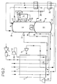
- an incoming stream of air is compressed at the compressor 2 to a pressure in the range of 5 to 6 atmospheres.
- the compressor 2 has an after cooler (not shown) associated with it to return the temperature of the air after compression to a value approaching that of the ambient air.
- the resulting compressed air stream is then passed through a purification apparatus 4 for removing water vapour, carbon dioxide and other impurities of relatively low volatility from the air by adsorption.
- a purification apparatus 4 for removing water vapour, carbon dioxide and other impurities of relatively low volatility from the air by adsorption.
- a plurality of beds of adsorbent is employed with only some beds being used to purify the air at any one time, the other beds being regenerated by means of hot gas.
- the resulting purified stream air then flows into a heat exchanger means 6 at its warm end 7 (at about ambient temperature) and through the heat exchanger 6, leaving its cold end 9 at approximately the saturation temperature of the air.
- the cooled air flows from the cold end 9 of the heat exchanger 6 into the bottom of a higher pressure stage 10 of a double rectification column 8 through an inlet 11.
- the rectification column 8 also includes a lower pressure stage 12 which is adapted to feed argon-enriched oxygen to an argon side rectification column 14.
- the columns 12 and 14 both contain low pressure drop liquid-vapour contact means (for example structured packing) to effect intimate contact and hence mass exchange between a generally descending liquid phase and a generally ascending vapour phase.
- the operating pressure at the top of the lower pressure stage 12 of the double rectification column 8, the number of theoretical stages of separation in both the high pressure stage 10 and the lower pressure stage 12 of the rectification column 8, and the average pressure drop per theoretical stage in each of the stages 10 and 12 of the rectification column 8 will determine the pressure to which the incoming air is compressed in the compressor 2, this pressure tending to be less the lower the average pressure drop per theoretical stage of the liquid-vapour contact means used in the stages 10 and 12 of the rectification column 8.
- the rectification column 8 is in other respects of a conventional kind.
- a condenser-reboiler 16 linking the lower pressure stage 12 and the higher pressure stage 10 of the double rectification column 8 provides liquid nitrogen reflux for the higher pressure stage 10.
- a descending liquid phase comes into contact with an ascending vapour phase with the result that mass exchange takes place therebetween.
- This vapour-liquid contact takes place on the surfaces of the liquid-vapour contact means (not shown) (for example, conventional sieve trays or a structured packing) employed in the higher pressure stage 10.
- the liquid phase as it descends the higher pressure stage 10 of the column 8 becomes progressively richer in oxygen and the vapour phase as it ascends the stage 10 becomes progressively richer in nitrogen.
- Substantially pure nitrogen vapour is thus provided at the top of the higher pressure stage 10.
- Some nitrogen vapour passes into the condenser-reboiler 16 and is condensed.
- the remainder leaves the column 8 through an outlet 18 and then passes back through the heat exchanger 6 from its cold end 9 to its warm end 7.
- the thus warmed nitrogen stream may be taken as product. If desired, however, all the nitrogen vapour may be condensed and no nitrogen product taken from the high pressure stage 10. Such a practice helps to maximise argon production.
- a stream of oxygen-rich liquid is withdrawn from the bottom of the higher pressure stage 10 of the column 8 through an outlet 22 and is then sub-cooled by passage through a heat exchanger 24.
- the resulting sub-cooled liquid-oxygen enriched air then passes through a Joule-Thomson valve 26 and is reduced in pressure to a level suitable for its introduction into the lower pressure stage 12 of the column 8.
- the majority of the resulting fluid stream is introduced into the lower pressure stage 12 of the column 8 through an inlet 28. This air is then separated in the lower pressure stage 12 of the column 8 into oxygen and nitrogen products as will be described below.
- a stream of liquid nitrogen condensate from the condenser-reboiler 16 is withdrawn from the higher pressure stage 10 of the rectification column 8 through an outlet 30, is sub-cooled by passage through a heat exchanger 32 and is then passed into the top of the lower pressure stage 12 of the rectification column 8 through an inlet 34.
- Liquid nitrogen thus descending the column and on the liquid-vapour contact means (not shown) comes into contact with ascending vapour.
- the liquid becomes progressively richer in oxygen.
- Substantially pure liquid oxygen collects at the bottom of the stage 12 and is reboiled by condensing nitrogen vapour in the condenser-reboiler 16, thereby creating an upward flow of vapour through the stage 12.
- a stream of gaseous oxygen product is withdrawn from the bottom region of the stage 12 through an outlet 36 and passes through the heat exchanger 6 from its cold end 9 to its warm end 7.
- a gaseous nitrogen product stream is withdrawn from the top of the lower pressure stage 12 of the rectification column 8 through an outlet 38 and passes first through the heat exchanger 32 countercurrently to the liquid nitrogen stream withdrawn through the outlet 30 from the top of the higher pressure stage 10 of the rectification column 8; then flows through the heat exchanger 24 countercurrently to the oxygen-enriched liquid withdrawn through the outlet 22 from the higher pressure stage 10 of the rectification column 8; and then flows through the heat exchanger 6 from its cold end 9 to its warm end 7.
- a stream of nitrogen containing a small amount of oxygen impurity is withdrawn from near the top of the lower pressure stage 12 of the rectification column 8 through an outlet 40 and returns cocurrently with the stream of nitrogen withdrawn through the outlet 38 flowing through heat exchangers 32, 24 and 6.
- This nitrogen stream may be used as a source of gas for regenerating the adsorbent beds of the purification apparatus 4.
- the lower pressure stage 12 of the rectification column 8 is also used to supply the argon column 14 with a stream of argon-enriched oxygen for separation. Accordingly, a stream of argon-enriched oxygen is withdrawn at a suitable level from the lower pressure stage 12 of the column 8 through an outlet 42 and introduced into the column 14 through an inlet 44. Reflux for the column 14 is provided by condensing vapour passing out of the top of the column 14 in a condenser 46 by means of a part of the expanded oxygen-rich liquid stream passing through the valve 26. A part of the resulting condensate is withdrawn through outlet 48 as crude argon product while the remainder returns to the top of the column 14 as reflux.
- Mass exchange takes place in the column 14 between the descending liquid and ascending vapour phases.
- a stream of liquid oxygen is returned to the lower pressure stage 12 of the column 8 through an inlet 50.
- the liquid oxygen-enriched air which passes through the condenser 46 is vaporised and the resulting vapour is that introduced into the stage 12 of the column 8 through the inlet 31.
- a part of the incoming compressed air stream leaving the purification apparatus 4 is taken upstream of the warm end 7 of the heat exchanger 6 and is further compressed in a compressor 52 having an after cooler (not shown) associated therewith.
- a stream of compressed air leaves the compressor 52 at a pressure in the range 8 to 10 bar and flows into the heat exchanger 6 through its warm end 7. This stream is further divided during its passage through the heat exchange 6.
- a subsidiary stream is taken therefrom at a temperature typically in the order of 200 to 250K and is expanded with the performance of external work in a first or warm turbine 54. The resulting expanded air leaves the turbine 54 typically at the pressure of the lower pressure stage 12 and then flows back into the heat exchanger 6 at an appropriate intermediate region thereof.
- the stream then continues its flow through the heat exchanger 6 in a direction cocurrent with that followed by main air stream, and leaves the heat exchanger 6 through its cold end 9.
- This air stream is then introduced into the lower pressure stage 12 of the rectification column 8 through the inlet 32.
- the remainder of that air stream from which the subsidiary stream is taken for expansion in the turbine 54 is withdrawn from the heat exchanger 6 at an intermediate temperature typically in the range 120 to 160K and is expanded in a second or cold turbine 56 to a temperature and pressure suitable for its introduction into the lower pressure stage 12 of the rectification column 8. After leaving the turbine 56 this stream is remixed with the other exhausted air stream and thus enters the lower pressure stage 12 of the rectification column 8 through the inlet 32.
- some or all of the air from the turbines 54 and 56 may alternatively be mixed with the waste nitrogen stream upstream of the cold end 9 of the heat exchanger 6 via conduit 55.
- one or both turbines 54 and 56 have their shafts coupled to the shaft of the compressor 52 and thus the work done by expansion of the air in the turbines 54 and 56 is able to be used to drive the compressor 52.
- FIG 2 there is illustrated a variant of the method and apparatus shown in Figure 1.
- all the air flowing through the compressor 52 is withdrawn for expansion in the turbine 54 at a temperature in the range 200 to 250K and returns to the heat exchanger 6 at a temperature in the range 120 to 150K.
- the turbine 56 and its associated conduits are omitted from the apparatus shown in Figure 2. Instead, a 'cold' nitrogen turbine 58 is provided.
- a part of the higher pressure nitrogen stream withdrawn from the outlet 18 of the higher pressure stage 10 of the rectification column 8 is taken at a temperature in the range of 120 to 150K from the heat exchanger 6, is expanded in the turbine 58 with the performance of external work, and is united with the nitrogen product stream (withdrawn from the lower pressure stage 12 of the rectification column 8 through the outlet 38) at the pressure and typically the temperature of that stream immediately upstream of its entry into the cold end 9 of the heat exchanger 6.
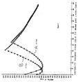
- the operation of the turbines 54 and 58 enable the temperature profile of the streams being warmed in the heat exchanger 6 to be kept in close conformity with that of the streams being cooled.
- Curve C illustrates the operation of the heat exchanger 6 in an apparatus as shown in Figure 1.
- the outlet pressure of the compressor 2 is 5.6 bar (560 kPa). Accordingly the air enters the higher pressure stage 10 of the double rectification column 8 through the inlet 11 at a pressure of about 5.2 bar (520 kPa).
- the area enclosed by Curve C is considerably less than that enclosed either by Curve A or Curve B.
- the method represented by Curve C is considerably more efficient than those represented by Curves A and B. Accordingly, the method and apparatus according to the invention make possible relatively efficient operation of the air separation plant when a low pressure drop liquid-vapour contact means is used in the rectification columns of the plant.
Claims (8)
- Procédé pour séparer, à partir de l'air, un produit constitué par de l'oxygène et un courant gazeux d'un produit constitué par de l'azote, obtenus à partir de l'air, le procédé comprenant l'abaissement de la température d'un courant d'air comprimé, par échange de chaleur dans un moyen d'échange de chaleur jusqu'à une valeur convenant pour sa séparation par rectification, l'introduction du courant d'air ainsi refroidi dans l'étage à plus haute pression d'une colonne double de rectification pour la séparation de l'air (en ses constituants), ladite colonne double de rectification comprenant un étage à plus basse pression et un étage à pression supérieure, l'utilisation de l'étage à haute pression de la colonne pour fournir l'azote gazeux servant de reflux et une alimentation, constituée par de l'air enrichi en oxygène, pour l'étage à plus basse pression, et le soutirage de l'oxygène comme produit et d'un courant d'azote gazeux de l'étage à plus basse pression, procédé dans lequel au moins l'étage à plus basse basse pression comprend un moyen de mise en contact liquide/vapeur à faible chute de pression, c'est-à-dire un moyen de mise en contact liquide/vapeur ayant une chute de pression inférieure à 400 Pa par étage ou plateau théorique de séparation, pour effectuer une mise en contact intime et donc un transfert en masse entre liquide et vapeur, l'étage à haute pression de la colonne double de rectification fonctionnant à une pression (à mi-chemin dans la montée dans l'étage à haute pression) se situant entre 450 et 550 kPa (4,5 à 5,5 bars), et une réfrigération étant créée pour le procédé par la réalisation d'une première détente de fluide avec réalisation d'un travail extérieur, cette détente produisant du fluide à une température nettement plus basse ou à une température inférieure à celle à laquelle ledit courant d'air comprimé quitte l'extrémité froide du moyen d'échange de chaleur, procédé caractérisé en ce que plus de 90 % du produit constitué par de l'oxygène et la totalité du produit constitué par de l'azote sont prélevés sous forme de gaz de la colonne double de rectification, et en ce qu'une seconde détente de fluide, avec réalisation d'un travail extérieur, est réalisée séparément de ladite première détente, ladite seconde détente prenant du fluide prélevé sur le moyen d'échange de chaleur à une température intermédiaire supérieure et renvoyant le fluide à une plus basse température intermédiaire vers cet échangeur de chaleur, lesdites deux températures intermédiaires se situant entre la température du courant d'air à l'extrémité froide et la température à l'extrémité chaude du moyen d'échange de chaleur.
- Procédé selon la revendication 1, dans lequel au moins ladite seconde détente est appliquée à de l'air comprimé prélevé sur le courant d'air comprimé.
- Procédé selon la revendication 1 ou 2, dans lequel l'air est soumis à ladite seconde détente, et l'air détendu résultant est renvoyé vers le moyen d'échange de chaleur ; il sort de l'extrémité froide du moyen d'échange de chaleur et est introduit dans l'étage à basse pression de la colonne double.
- Procédé selon l'une quelconque des revendications précédentes, dans lequel la seconde détente produit du fluide à une température comprise entre 120 et 160 K.
- Procédé tel que revendiqué dans l'une quelconque des revendications précédentes, dans lequel le fluide destiné à la première détente est prélevé sur le moyen d'échange de chaleur en étant à une température comprise entre 120 et 160 K.
- Procédé selon l'une quelconque des revendications précédentes, dans lequel l'une des détentes est appliquée à un courant d'azote soutiré de l'étage haute pression de la colonne de rectification.
- Procédé tel que revendiqué dans l'une quelconque des revendications précédentes, dans lequel l'oxygène produit est prélevé entièrement sous forme de gaz.
- Procédé selon l'une quelconque des revendications précédentes, dans lequel le moyen de mise en contact liquide/vapeur avec faible chute de pression est constitué par, ou comprend, un garnissage structuré.
Applications Claiming Priority (2)
| Application Number | Priority Date | Filing Date | Title |
|---|---|---|---|
| GB909008752A GB9008752D0 (en) | 1990-04-18 | 1990-04-18 | Air separation |
| GB9008752 | 1990-04-18 |
Publications (3)
| Publication Number | Publication Date |
|---|---|
| EP0454327A1 EP0454327A1 (fr) | 1991-10-30 |
| EP0454327B1 EP0454327B1 (fr) | 1994-12-07 |
| EP0454327B2 true EP0454327B2 (fr) | 2000-05-31 |
Family
ID=10674633
Family Applications (1)
| Application Number | Title | Priority Date | Filing Date |
|---|---|---|---|
| EP91303237A Expired - Lifetime EP0454327B2 (fr) | 1990-04-18 | 1991-04-11 | Séparation d'air |
Country Status (9)
| Country | Link |
|---|---|
| US (1) | US5123249A (fr) |
| EP (1) | EP0454327B2 (fr) |
| JP (1) | JP3169627B2 (fr) |
| KR (1) | KR100190258B1 (fr) |
| CN (1) | CN1050418C (fr) |
| CA (1) | CA2040796C (fr) |
| DE (1) | DE69105601T3 (fr) |
| GB (1) | GB9008752D0 (fr) |
| ZA (1) | ZA912631B (fr) |
Families Citing this family (25)
| Publication number | Priority date | Publication date | Assignee | Title |
|---|---|---|---|---|
| FR2688052B1 (fr) * | 1992-03-02 | 1994-05-20 | Maurice Grenier | Procede et installation de production d'oxygene et/ou d'azote gazeux sous pression par distillation d'air. |
| FR2689223B1 (fr) * | 1992-03-24 | 1994-05-06 | Air Liquide | Procede et installation de transfert de fluide en provenance d'une colonne de distillation, notamment d'air. |
| US5337570A (en) * | 1993-07-22 | 1994-08-16 | Praxair Technology, Inc. | Cryogenic rectification system for producing lower purity oxygen |
| US5379598A (en) * | 1993-08-23 | 1995-01-10 | The Boc Group, Inc. | Cryogenic rectification process and apparatus for vaporizing a pumped liquid product |
| FR2714721B1 (fr) * | 1993-12-31 | 1996-02-16 | Air Liquide | Procédé et installation de liquéfaction d'un gaz. |
| FR2718518B1 (fr) * | 1994-04-12 | 1996-05-03 | Air Liquide | Procédé et installation pour la production de l'oxygène par distillation de l'air. |
| US5758515A (en) * | 1997-05-08 | 1998-06-02 | Praxair Technology, Inc. | Cryogenic air separation with warm turbine recycle |
| US5802873A (en) * | 1997-05-08 | 1998-09-08 | Praxair Technology, Inc. | Cryogenic rectification system with dual feed air turboexpansion |
| US6006545A (en) * | 1998-08-14 | 1999-12-28 | L'air Liquide, Societe Anonyme Pour L'etude Et L'exploitation Des Procedes | Liquefier process |
| FR2844344B1 (fr) * | 2002-09-11 | 2005-04-08 | Air Liquide | Installation de production de grandes quantites d'oxygene et/ou d'azote |
| FR2865024B3 (fr) * | 2004-01-12 | 2006-05-05 | Air Liquide | Procede et installation de separation d'air par distillation cryogenique |
| CN100357685C (zh) * | 2004-10-28 | 2007-12-26 | 苏州市兴鲁空分设备科技发展有限公司 | 一种空气分离的方法和装置 |
| CN100357684C (zh) * | 2004-10-28 | 2007-12-26 | 苏州市兴鲁空分设备科技发展有限公司 | 一种空气分离的方法和装置 |
| JP4515225B2 (ja) * | 2004-11-08 | 2010-07-28 | 大陽日酸株式会社 | 窒素製造方法及び装置 |
| US8020408B2 (en) * | 2006-12-06 | 2011-09-20 | Praxair Technology, Inc. | Separation method and apparatus |
| FR2913760B1 (fr) * | 2007-03-13 | 2013-08-16 | Air Liquide | Procede et appareil de production de gaz de l'air sous forme gazeuse et liquide a haute flexibilite par distillation cryogenique |
| DE102007031765A1 (de) * | 2007-07-07 | 2009-01-08 | Linde Ag | Verfahren zur Tieftemperaturzerlegung von Luft |
| CN101464085B (zh) * | 2009-01-08 | 2011-01-26 | 北京名都厚德科技有限公司 | 一种超低压单塔深冷空分工艺 |
| JP5647853B2 (ja) * | 2010-10-14 | 2015-01-07 | 大陽日酸株式会社 | 空気液化分離方法及び装置 |
| TR201808162T4 (tr) * | 2014-07-05 | 2018-07-23 | Linde Ag | Havanın düşük sıcaklıkta ayrıştırılması vasıtasıyla bir basınçlı gaz ürününün kazanılmasına yönelik yöntem ve cihaz. |
| PL3196574T3 (pl) * | 2016-01-21 | 2021-10-18 | Linde Gmbh | Sposób i urządzenie do wytwarzania gazowego azotu pod ciśnieniem przez kriogeniczną separację powietrza |
| JP6440232B1 (ja) * | 2018-03-20 | 2018-12-19 | レール・リキード−ソシエテ・アノニム・プール・レテュード・エ・レクスプロワタシオン・デ・プロセデ・ジョルジュ・クロード | 製品窒素ガスおよび製品アルゴンの製造方法およびその製造装置 |
| US11846468B2 (en) * | 2018-10-23 | 2023-12-19 | Linde Gmbh | Method and unit for low-temperature air separation |
| CN115461584A (zh) * | 2020-05-11 | 2022-12-09 | 普莱克斯技术有限公司 | 用于从中压低温空气分离单元回收氮、氩和氧的系统和方法 |
| CN115485519A (zh) | 2020-05-15 | 2022-12-16 | 普莱克斯技术有限公司 | 用于产生氮和氩的低温空气分离单元的集成式氮液化器 |
Family Cites Families (12)
| Publication number | Priority date | Publication date | Assignee | Title |
|---|---|---|---|---|
| US3086371A (en) * | 1957-09-12 | 1963-04-23 | Air Prod & Chem | Fractionation of gaseous mixtures |
| US4224045A (en) * | 1978-08-23 | 1980-09-23 | Union Carbide Corporation | Cryogenic system for producing low-purity oxygen |
| DE2854508C2 (de) * | 1978-12-16 | 1981-12-03 | Linde Ag, 6200 Wiesbaden | Verfahren und Vorrichtung zur Tieftemperaturzerlegung eines Gasgemisches |
| FR2461906A1 (fr) * | 1979-07-20 | 1981-02-06 | Air Liquide | Procede et installation cryogeniques de separation d'air avec production d'oxygene sous haute pression |
| US4410343A (en) * | 1981-12-24 | 1983-10-18 | Union Carbide Corporation | Air boiling process to produce low purity oxygen |
| DE3367023D1 (en) * | 1982-05-03 | 1986-11-20 | Linde Ag | Process and apparatus for obtaining gaseous oxygen at elevated pressure |
| JPS61130769A (ja) * | 1984-11-30 | 1986-06-18 | 株式会社日立製作所 | 低温廃ガスを利用した寒冷発生方法 |
| GB8622055D0 (en) * | 1986-09-12 | 1986-10-22 | Boc Group Plc | Air separation |
| DE3738559A1 (de) * | 1987-11-13 | 1989-05-24 | Linde Ag | Verfahren zur luftzerlegung durch tieftemperaturrektifikation |
| US4836836A (en) * | 1987-12-14 | 1989-06-06 | Air Products And Chemicals, Inc. | Separating argon/oxygen mixtures using a structured packing |
| US4871382A (en) * | 1987-12-14 | 1989-10-03 | Air Products And Chemicals, Inc. | Air separation process using packed columns for oxygen and argon recovery |
| ITMI20021467A1 (it) * | 2002-07-04 | 2004-01-05 | Francesco Paolo Terranova | Impianto per produrre energia elettrica dal movimento delle onde del mare |
-
1990
- 1990-04-18 GB GB909008752A patent/GB9008752D0/en active Pending
-
1991
- 1991-04-09 ZA ZA912631A patent/ZA912631B/xx unknown
- 1991-04-11 EP EP91303237A patent/EP0454327B2/fr not_active Expired - Lifetime
- 1991-04-11 DE DE69105601T patent/DE69105601T3/de not_active Expired - Fee Related
- 1991-04-17 US US07/686,738 patent/US5123249A/en not_active Expired - Lifetime
- 1991-04-17 KR KR1019910006113A patent/KR100190258B1/ko not_active IP Right Cessation
- 1991-04-18 CA CA002040796A patent/CA2040796C/fr not_active Expired - Fee Related
- 1991-04-18 JP JP08681591A patent/JP3169627B2/ja not_active Expired - Fee Related
- 1991-04-18 CN CN91102951A patent/CN1050418C/zh not_active Expired - Fee Related
Also Published As
| Publication number | Publication date |
|---|---|
| US5123249A (en) | 1992-06-23 |
| DE69105601T2 (de) | 1995-04-27 |
| CN1050418C (zh) | 2000-03-15 |
| DE69105601D1 (de) | 1995-01-19 |
| ZA912631B (en) | 1992-01-29 |
| DE69105601T3 (de) | 2001-02-01 |
| GB9008752D0 (en) | 1990-06-13 |
| AU626752B2 (en) | 1992-08-06 |
| EP0454327B1 (fr) | 1994-12-07 |
| JP3169627B2 (ja) | 2001-05-28 |
| EP0454327A1 (fr) | 1991-10-30 |
| CA2040796C (fr) | 2001-12-25 |
| KR100190258B1 (ko) | 1999-06-01 |
| KR910018064A (ko) | 1991-11-30 |
| JPH0626759A (ja) | 1994-02-04 |
| CN1056566A (zh) | 1991-11-27 |
| CA2040796A1 (fr) | 1991-10-19 |
| AU7435791A (en) | 1991-10-24 |
Similar Documents
| Publication | Publication Date | Title |
|---|---|---|
| EP0454327B2 (fr) | Séparation d'air | |
| US5533339A (en) | Air separation | |
| US5511381A (en) | Air separation | |
| US5546766A (en) | Air separation | |
| US5582035A (en) | Air separation | |
| EP0542539B1 (fr) | Séparation d'air | |
| EP0687876B1 (fr) | Séparation de l'air | |
| EP0577349B1 (fr) | Séparation d'air | |
| US5485729A (en) | Air separation | |
| EP0694744B1 (fr) | Séparation de l'air | |
| EP1243883A1 (fr) | Séparation d'air | |
| EP0752566B1 (fr) | Séparation d'air | |
| US5361590A (en) | Air separation | |
| US5309721A (en) | Air separation | |
| EP0828124B1 (fr) | Séparation d'air | |
| EP0831284B1 (fr) | Séparation d'air | |
| EP0828123B1 (fr) | Séparation d'air | |
| US5692397A (en) | Air separation | |
| EP1120616A2 (fr) | Méthode de séparation de l'air | |
| GB2266363A (en) | Air separation |
Legal Events
| Date | Code | Title | Description |
|---|---|---|---|
| PUAI | Public reference made under article 153(3) epc to a published international application that has entered the european phase |
Free format text: ORIGINAL CODE: 0009012 |
|
| AK | Designated contracting states |
Kind code of ref document: A1 Designated state(s): BE DE DK FR GB IT NL SE |
|
| 17P | Request for examination filed |
Effective date: 19911112 |
|
| 17Q | First examination report despatched |
Effective date: 19920414 |
|
| GRAA | (expected) grant |
Free format text: ORIGINAL CODE: 0009210 |
|
| ITF | It: translation for a ep patent filed |
Owner name: BARZANO' E ZANARDO MILANO S.P.A. |
|
| AK | Designated contracting states |
Kind code of ref document: B1 Designated state(s): BE DE DK FR GB IT NL SE |
|
| PG25 | Lapsed in a contracting state [announced via postgrant information from national office to epo] |
Ref country code: NL Effective date: 19941207 Ref country code: DK Effective date: 19941207 Ref country code: BE Effective date: 19941207 |
|
| ET | Fr: translation filed | ||
| REF | Corresponds to: |
Ref document number: 69105601 Country of ref document: DE Date of ref document: 19950119 |
|
| PG25 | Lapsed in a contracting state [announced via postgrant information from national office to epo] |
Ref country code: SE Effective date: 19950307 |
|
| NLV1 | Nl: lapsed or annulled due to failure to fulfill the requirements of art. 29p and 29m of the patents act | ||
| PLBI | Opposition filed |
Free format text: ORIGINAL CODE: 0009260 |
|
| 26 | Opposition filed |
Opponent name: L'AIR LIQUIDE, S.A. POUR L'ETUDE ET L'EXPLOITATION Effective date: 19950901 |
|
| PLBF | Reply of patent proprietor to notice(s) of opposition |
Free format text: ORIGINAL CODE: EPIDOS OBSO |
|
| PLAW | Interlocutory decision in opposition |
Free format text: ORIGINAL CODE: EPIDOS IDOP |
|
| APAC | Appeal dossier modified |
Free format text: ORIGINAL CODE: EPIDOS NOAPO |
|
| APAE | Appeal reference modified |
Free format text: ORIGINAL CODE: EPIDOS REFNO |
|
| APAC | Appeal dossier modified |
Free format text: ORIGINAL CODE: EPIDOS NOAPO |
|
| APAC | Appeal dossier modified |
Free format text: ORIGINAL CODE: EPIDOS NOAPO |
|
| PLAW | Interlocutory decision in opposition |
Free format text: ORIGINAL CODE: EPIDOS IDOP |
|
| PUAH | Patent maintained in amended form |
Free format text: ORIGINAL CODE: 0009272 |
|
| STAA | Information on the status of an ep patent application or granted ep patent |
Free format text: STATUS: PATENT MAINTAINED AS AMENDED |
|
| 27A | Patent maintained in amended form |
Effective date: 20000531 |
|
| AK | Designated contracting states |
Kind code of ref document: B2 Designated state(s): BE DE DK FR GB IT NL SE |
|
| ET3 | Fr: translation filed ** decision concerning opposition | ||
| ITF | It: translation for a ep patent filed |
Owner name: BARZANO' E ZANARDO MILANO S.P.A. |
|
| REG | Reference to a national code |
Ref country code: GB Ref legal event code: IF02 |
|
| PGFP | Annual fee paid to national office [announced via postgrant information from national office to epo] |
Ref country code: FR Payment date: 20020319 Year of fee payment: 12 |
|
| PGFP | Annual fee paid to national office [announced via postgrant information from national office to epo] |
Ref country code: GB Payment date: 20020403 Year of fee payment: 12 |
|
| PGFP | Annual fee paid to national office [announced via postgrant information from national office to epo] |
Ref country code: DE Payment date: 20020418 Year of fee payment: 12 |
|
| PG25 | Lapsed in a contracting state [announced via postgrant information from national office to epo] |
Ref country code: GB Free format text: LAPSE BECAUSE OF NON-PAYMENT OF DUE FEES Effective date: 20030411 |
|
| PG25 | Lapsed in a contracting state [announced via postgrant information from national office to epo] |
Ref country code: DE Free format text: LAPSE BECAUSE OF NON-PAYMENT OF DUE FEES Effective date: 20031101 |
|
| GBPC | Gb: european patent ceased through non-payment of renewal fee |
Effective date: 20030411 |
|
| PG25 | Lapsed in a contracting state [announced via postgrant information from national office to epo] |
Ref country code: FR Free format text: LAPSE BECAUSE OF NON-PAYMENT OF DUE FEES Effective date: 20031231 |
|
| REG | Reference to a national code |
Ref country code: FR Ref legal event code: ST |
|
| PG25 | Lapsed in a contracting state [announced via postgrant information from national office to epo] |
Ref country code: IT Free format text: LAPSE BECAUSE OF NON-PAYMENT OF DUE FEES;WARNING: LAPSES OF ITALIAN PATENTS WITH EFFECTIVE DATE BEFORE 2007 MAY HAVE OCCURRED AT ANY TIME BEFORE 2007. THE CORRECT EFFECTIVE DATE MAY BE DIFFERENT FROM THE ONE RECORDED. Effective date: 20050411 |
|
| APAH | Appeal reference modified |
Free format text: ORIGINAL CODE: EPIDOSCREFNO |