EP1120218A1 - Vorrichtung zur Herstellung eines Artikels aus expandiertem Material - Google Patents
Vorrichtung zur Herstellung eines Artikels aus expandiertem Material Download PDFInfo
- Publication number
- EP1120218A1 EP1120218A1 EP01101234A EP01101234A EP1120218A1 EP 1120218 A1 EP1120218 A1 EP 1120218A1 EP 01101234 A EP01101234 A EP 01101234A EP 01101234 A EP01101234 A EP 01101234A EP 1120218 A1 EP1120218 A1 EP 1120218A1
- Authority
- EP
- European Patent Office
- Prior art keywords
- structural members
- expansion
- molded articles
- belts
- passageway
- Prior art date
- Legal status (The legal status is an assumption and is not a legal conclusion. Google has not performed a legal analysis and makes no representation as to the accuracy of the status listed.)
- Withdrawn
Links
Images

Classifications
-
- B—PERFORMING OPERATIONS; TRANSPORTING
- B29—WORKING OF PLASTICS; WORKING OF SUBSTANCES IN A PLASTIC STATE IN GENERAL
- B29C—SHAPING OR JOINING OF PLASTICS; SHAPING OF MATERIAL IN A PLASTIC STATE, NOT OTHERWISE PROVIDED FOR; AFTER-TREATMENT OF THE SHAPED PRODUCTS, e.g. REPAIRING
- B29C44/00—Shaping by internal pressure generated in the material, e.g. swelling or foaming ; Producing porous or cellular expanded plastics articles
- B29C44/20—Shaping by internal pressure generated in the material, e.g. swelling or foaming ; Producing porous or cellular expanded plastics articles for articles of indefinite length
- B29C44/30—Expanding the moulding material between endless belts or rollers
- B29C44/304—Adjusting the belt or roller pressure
Definitions
- the present invention relates to apparatus for producing expansion-molded articles.
- apparatus for producing expansion-molded articles capable of producing expansion-molded articles continuously by thermal expansion of synthetic resin foamed and expanded beads (hereinafter to be referred to as "foamed beads") and mutually fusion-bonding these foamed beads.
- the continuous molding method has the advantages that expansion-molded articles (hereinbelow expansion-molded articles may be abbreviated to molded articles) can be manufactured continuously and that molded articles of long dimensions can be obtained; as a method of continuously molding polystyrene resin foamed beads, for example the method disclosed in published Japanese Patent Number Sho. 52-2424 is known. Also, as methods of continuously molding polyolefin resin foamed beads, the methods of Laid-open Japanese Patent publication number Hei. 9-104026, Laid-open Japanese Patent publication number Hei. 9-104027, Laid-open Japanese Patent publication number 2000-6253, Laid-open Japanese Patent publication number 2000-15708 and US Patent Number 5968430 previously applied for by the present applicants are known.
- conventional apparatus for manufacturing expansion-molded articles used in the method of continuous molding described above is constructed such that foamed beads are supplied between continuously traveling belts along upper and lower surfaces within a passageway whereof the cross-section defined by the structural members constitutes an approximately rectangular shape, these foamed beads being expanded by heating while they are fed in a heating region and these foamed beads being mutually fusion-bonded; so when it is desired to alter the thickness or width of the expansion-molded article which is to be obtained, it is necessary to replace the belt and/or structural members by ones of different width; i.e.
- an object of the present invention is to provide apparatus for producing expansion-molded articles wherein the thickness and/or width of the molded articles that are to be manufactured can easily be altered.
- the apparatus for manufacturing expansion-molded articles according to the invention comprises sealing means for preventing leakage of heating steam at the location of contact of the movably constituted structural member(s) and the structural members that sandwich the movably constituted structural member(s).
- the movably constituted structural member(s) may be supported on a shaft(s) that is/are reciprocated by rotation of a screw(s).
- the movably constituted structural member(s) may be supported by a rod(s) of a cylinder(s).
- the apparatus for manufacturing according to the present invention comprises belts that respectively continuously travel along the inside face of the side-face structural members.
- the belts that move along the inside faces of the side-face structural members are provided extending from the commencement of the heating region to the end of the cooling region.
- the apparatus for manufacturing according to the present invention embraces apparatus wherein means for adjusting the angle of inclination of the belt on the upper side in the region of supply of the foamed beads are provided on the upper belt. Also it embraces apparatus wherein projections are provided in the vicinity of the inlet of the passageway.
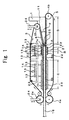
- Figure 1 shows an example of apparatus for producing expansion-molded articles according to the present invention, this molding apparatus comprising: a hopper 1 for storing foamed beads, a belt 3 that travels continuously in endless fashion between upper rolls 2a, 2b, and a belt 5 that travels continuously in endless fashion between lower rolls 4a, 4b.
- the foamed beads 11 that are supplied from hopper 1 move sandwiched by belts 3 and 5 through a passageway A and are expanded by being heated by steam in heating region B; thus the beads are mutually fusion-bonded and are then cooled in cooling region C to obtain the molded article.
- upper roll 2a and lower roll 4a perform drive rotation
- upper roll 2b and lower roll 4b are arranged such that upper belt 3 and lower belt 5 slide over the circumferential surfaces of these respective rolls 2b, 4b without these rotating. Slidability at these surfaces is improved by the provision of slide comprising polytetrafluoroethylene (Teflon) or the like at the surfaces of rolls 2b and 4b that contact the belts.
- Upper roll 2b is constituted such that its position can be moved vertically by drive means 24, the arrangement being such that the angle of inclination á of the upper belt 3 in the foamed bead supply region D can be altered by moving upper roll 2b vertically.
- auxiliary plate 6 is an auxiliary plate, this auxiliary plate 6 being constituted such that its angle with belt 3 changes when the angle of inclination á of upper belt 3 is adjusted. Also, upper roll 2a is moved vertically by drive means 24, the arrangement being such that its separation between upper roll 2a and lower roll 4a can be adjusted in accordance with the thickness of molded article 16.
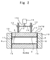
- the foamed beads supplied from hopper 1 are sandwiched between belts 3 and 5, and are fed into passageway A having a space section of approximately rectangular cross-section defined by upper and lower structural members 7a, 7b, and 8a, 8b and side-face structural members 9 and 10 ( Figure 2); the arrangement is such that the belt 3 and the belt 5 travel located between the structural members 7a, 7b and 8a, 8b in this passageway A.
- On the upper structural member 7a and the lower structural member 8a there are respectively provided a steam supply unit 21 and a suction unit 22 upstream and downstream of this steam supply unit 21. It is not essential to provide these suction units 22, but it is preferable to do so.
- On the upper structural member 7b and the lower structural member 8b there are respectively provided cooling means 23.
- the structural members 7a, 7b, 8a, 8b, 9, 10 and auxiliary plate 6 are made of metal material such as aluminum board, plate or plank; slide such as Teflon, not shown, is mounted on their faces on the sides contacting belts 3, 5 so as to facilitate sliding of belts 3, 5.
- the continuously traveling belts could be provided not merely above and below but also at both side faces; if continuously traveling belts 17, 18 are provided in endless fashion on the inside faces of side-face structural members 9, 10 at both sides as shown in Figure 2, the shape and the appearance of the side face portions of the molded article 16 obtained can be improved. If belts 17, 18 are provided on the inside faces of side-face structural members 9, 10, it is preferable that these belts 17, 18 should be provided extending at least from the commencement of heating region B to the end of cooling region C.
- the upper structural members 7a, 7b and lower structural members 8a, 8b are provided sandwiched between the side-face structural members 9 and 10, upper structural members 7a, 7b being supported on shafts 13 shaped male-screw that are reciprocated vertically by the rotation of female screws 12.
- Screws 12 are connected with the shafts 15a of motors 15 by for example belts 14 so that the rotation of motors 15 is transmitted to screws 12 and when screws 12 rotate the rotary movement of screws 12 is converted into vertical movement of shafts 13, causing the upper structural members 7a, 7b that are supported on shafts 13 to be moved vertically.
- the height of passageway A can be changed in accordance with the thickness of the molded article 16 that is to be obtained.
- the bottom end edges of the side faces of these structural members 7a, 7b should move vertically within a range such that they do not depart from the positions of side-face structural members 9, 10, but, if belts 17, 18 are also provided at the side faces, it is preferable that the bottom end edges of structural members 7a, 7b should be moved vertically within a range such that they do not depart from the upper end edges of belts 17, 18. Also, in order to prevent leakage of steam from the joints between the upper and lower structural members and the side-face structural members it is desirable to provide sealing members 19 at the joints.
- a sealing member 19 is provided at the region of contact of at least movably arranged upper structural members 7a, 7b and side-face structural members 9, 10; preferably a sealing member 19 is mounted on the upper ends on the inside face of side-face structural members 9, 10 which do not move.
- a synthetic rubber with high heat resistance such as a silicon rubber is preferably used.
- any means that is capable of moving the structural members could be employed: there is no restriction to a method in which the structural members are supported by shafts 13 which are reciprocated by rotation of screws 12; for example, movement could be effected by a hydraulic cylinder or the like linked to the structural members.
- both upper and lower structural members could respectively consist of three or more plate type structural members.
- both upper and lower structural members could respectively consist of one plate type structural member.
- the thickness of the molded article 16 was arranged to be variable by moving the upper structural members 7a, 7b vertically
- sealing members 19 it is desirable to provide sealing members 19 at the location where side-face structural members 9, 10 are constituted so as to be movable and upper and lower structural members 7a (or 7b) and 8a (or 8b) make contact in order to prevent leakage of steam. It is more preferable to provide the sealing members 19 at the both ends on the inner face side of the upper structural members 7a, 7b and the lower structural members 8a, 8b that do not move.
- both side-face structural members 9 and 10 could respectively consist of two or more plate type structural members.
- the means for moving the side-face structural members 9 and 10 is not restricted to a cylinder as described above and any desired means could be adopted.
- a thermoplastic resin can be used, especially a polyolefin resin with at least 50 mol% olefin unit constituents is preferable, such as a homopolymer of olefins such as polyethylene, polypropylene or polybutylene, a copolymer of olefins such as ethylene-butene random copolymer, ethylene-hexene random copolymer, ethylene-octene random copolymer, ethylene-propylene block copolymer, ethylene-propylene random copolymer, ethylene-propylene-butene random copolymer, or a graft polymer obtained by graft polymerization by impregnating a homopolymer of the above polyolefins or a copolymer of olefins with styrene or reactive vinyl monomer such as acrylic acid
- the upper structural members 7a, 7b and upper roll 2a are moved into position in accordance with the thickness of the molded article 16 that is desired to be obtained.
- Foamed beads 11 supplied from hopper 1 are fed in the direction of the heating region B sandwiched between the belts 3 and 5.
- the angle of inclination á of belt 3 is adjusted such that the foamed beads are compressed to a bulk volume of 40 to 95% of their original bulk volume, whilst the foamed beads supplied from hopper are being fed towards the heating region B.
- the angle of inclination á of the inclined upper belt 3 is normally less than 10° and even more preferably is 1 to 5°.
- the provision of a suction unit 22 for sucking up steam or steam drainage both upstream and downstream of steam supply unit 21 can prevent accumulation of such steam drainage in passageway A from interfering with the supply of foamed beads (in particular, the action of a suction unit 22 on the upstream side of steam supply unit 21), or can prevent problems such as generation of warping in the molded article caused by reduction in the cooling effect of the molded article due to this steam drainage (in particular, the action of a suction unit 22 on the downstream side of steam supply unit 21).
- the steam is supplied into passageway A from steam supply unit 21 through the through-holes of the upper and lower structural members 7a, 8a and/or through-holes provided in belts 3, 5.
- the pressure of the steam supplied from steam supply unit 21 is usually 9.8 to 39.2 N/cm 2 G.
- the foamed beads that are heated by steam are expanded with the result that the mutual gaps between beads in passageway A are filled and the beads are mutually fusion-bonded to form a molded article (at this time point, its condition is not what might be called a complete molded article, but, since mutual fusion between the foamed beads has occurred, it will for convenience be referred to as a molded article), after which they are conveyed into cooling region C equipped with cooling means 23.
- cooling means 23 for example a cooling plate in which cooling water circulation pipes are inserted may be employed. The above steps are repeated continuously to obtain an elongate molded article 16.
- steam supply units 21, suction units 22 and cooling means 23 need not be provided exclusively on the side of the upper and lower structural members 7a, 7b, 8a, 8b, but could also be provided on the side of side-face structural members 9 and 10.
- the case was illustrated in which only a single set of steam supply units 21 was provided, above and below; however, the steam supply units need not necessarily be only a single set: two or more sets thereof could be provided.
- steam of a temperature capable of effecting expansion of the foamed beads but little or no fusion of the foamed beads surface is supplied from the steam supply unit on the upstream side, thereby heating and expanding the foamed beads, after which, steam of a temperature enough to effect fusion of the foamed beads surface is supplied from the steam supply unit on the downstream side, thereby causing the expanded foamed beads to mutually fusion-bond.
- polyolefin resin foamed beads are employed as foamed beads 11, as disclosed in US Patent Number 5968430, it is desirable to provide projections 25 in the vicinity of the inlet of passageway A, so that, after compressing the foamed beads 11 between these projections 25, a part or the whole of the compression is removed before they are passed through the heating region to be molded.
- the foamed beads are compressed to a bulk volume of 10 to 60% of their original bulk volume. In this way, back-flow of foamed beads and leakage of steam can be largely prevented.
- a molded article 16 of constant thickness can be obtained, if it is desired to obtain molded articles of different thickness, this can be achieved by molding as described above after moving upper structural members 7a, 7b and upper roll 2a in accordance with the thickness of the molded article that is sought to be obtained. Also, if molded articles of different width are to be obtained, as shown in Figure 3, these can be molded using apparatus in which the side-face structural members 9 and 10 are made movable in the lateral direction.
- elongate molded articles can be obtained which could not be obtained by the batch system. Also, with apparatus according to the present invention, even when molded articles of different thickness and width are to be obtained, this can easily be coped with, and molded articles of different thickness or width can be manufactured efficiently.
Landscapes
- Moulds For Moulding Plastics Or The Like (AREA)
- Molding Of Porous Articles (AREA)
- Casting Or Compression Moulding Of Plastics Or The Like (AREA)
Applications Claiming Priority (2)
| Application Number | Priority Date | Filing Date | Title |
|---|---|---|---|
| JP2000013238 | 2000-01-21 | ||
| JP2000013238A JP2001198939A (ja) | 2000-01-21 | 2000-01-21 | 発泡成形体の製造装置 |
Publications (1)
| Publication Number | Publication Date |
|---|---|
| EP1120218A1 true EP1120218A1 (de) | 2001-08-01 |
Family
ID=18540852
Family Applications (1)
| Application Number | Title | Priority Date | Filing Date |
|---|---|---|---|
| EP01101234A Withdrawn EP1120218A1 (de) | 2000-01-21 | 2001-01-19 | Vorrichtung zur Herstellung eines Artikels aus expandiertem Material |
Country Status (3)
| Country | Link |
|---|---|
| US (1) | US6537054B2 (de) |
| EP (1) | EP1120218A1 (de) |
| JP (1) | JP2001198939A (de) |
Cited By (2)
| Publication number | Priority date | Publication date | Assignee | Title |
|---|---|---|---|---|
| WO2009001213A3 (en) * | 2007-06-26 | 2009-06-04 | Gilanberry Trading Ltd | Apparatus and method for continuously forming an element made of expanded plastic material and1 construction element |
| EP2366532A1 (de) * | 2010-03-19 | 2011-09-21 | Ignucell AB | Vorrichtung und Verfahren zur Herstellung von Isolier- und Drainageplatten |
Families Citing this family (28)
| Publication number | Priority date | Publication date | Assignee | Title |
|---|---|---|---|---|
| US7128561B2 (en) * | 2003-06-30 | 2006-10-31 | Owens Corning Fiberglas Technology, Inc. | Surface treatment for blanket of thermoplastic fibers |
| US7763341B2 (en) | 2004-01-23 | 2010-07-27 | Century-Board Usa, Llc | Filled polymer composite and synthetic building material compositions |
| US7211206B2 (en) * | 2004-01-23 | 2007-05-01 | Century-Board Usa Llc | Continuous forming system utilizing up to six endless belts |
| CN101111353B (zh) * | 2004-06-24 | 2011-09-28 | 世纪-博得美国公司 | 用于三维泡沫产品的连续成型设备 |
| US7794224B2 (en) | 2004-09-28 | 2010-09-14 | Woodbridge Corporation | Apparatus for the continuous production of plastic composites |
| US8752348B2 (en) | 2005-02-25 | 2014-06-17 | Syntheon Inc. | Composite pre-formed construction articles |
| AU2006216460A1 (en) * | 2005-02-25 | 2006-08-31 | Nova Chemicals Inc. | Lightweight compositions and articles containing such |
| CN104453081A (zh) * | 2005-02-25 | 2015-03-25 | 诺瓦化学品公司 | 复合预制建筑物面板、建筑物和框架壁骨 |
| US7744692B2 (en) | 2005-03-22 | 2010-06-29 | Nova Chemicals, Inc. | Lightweight concrete compositions |
| US20070225419A1 (en) | 2006-03-24 | 2007-09-27 | Century-Board Usa, Llc | Polyurethane composite materials |
| US7767122B2 (en) * | 2006-04-26 | 2010-08-03 | Fred Svirklys | Process and apparatus for continuous production of foam sheets |
| US7677880B2 (en) * | 2007-01-23 | 2010-03-16 | Formax, Inc. | Apparatus for forming hand-formed style patty using a patty-forming machine |
| US7677009B2 (en) * | 2007-02-02 | 2010-03-16 | Nova Chemicals Inc. | Roof truss system |
| US8048219B2 (en) | 2007-09-20 | 2011-11-01 | Nova Chemicals Inc. | Method of placing concrete |
| US20090078161A1 (en) * | 2007-09-20 | 2009-03-26 | Nova Chemicals Inc. | Methods of minimizing concrete cracking and shrinkage |
| DE102009007901B4 (de) * | 2009-02-06 | 2012-11-22 | Benteler Automobiltechnik Gmbh | Verfahren zur Herstellung eines Kraftfahrzeugbauteils und Kraftfahrzeugbauteil |
| US9481759B2 (en) | 2009-08-14 | 2016-11-01 | Boral Ip Holdings Llc | Polyurethanes derived from highly reactive reactants and coal ash |
| US8846776B2 (en) | 2009-08-14 | 2014-09-30 | Boral Ip Holdings Llc | Filled polyurethane composites and methods of making same |
| BE1019507A5 (nl) * | 2010-09-17 | 2012-08-07 | Tech Bureel Panigo Nv | Productie van gelaagde styreengepolymeriseerde platen. |
| WO2013052732A1 (en) | 2011-10-07 | 2013-04-11 | Boral Industries Inc. | Inorganic polymer/organic polymer composites and methods of making same |
| WO2014168633A1 (en) | 2013-04-12 | 2014-10-16 | Boral Ip Holdings (Australia) Pty Limited | Composites formed from an absorptive filler and a polyurethane |
| WO2016018226A1 (en) | 2014-07-28 | 2016-02-04 | Crocco Guy | The use of evaporative coolants to manufacture filled polyurethane composites |
| WO2016022103A1 (en) | 2014-08-05 | 2016-02-11 | Amitabha Kumar | Filled polymeric composites including short length fibers |
| US9988512B2 (en) | 2015-01-22 | 2018-06-05 | Boral Ip Holdings (Australia) Pty Limited | Highly filled polyurethane composites |
| WO2016195717A1 (en) | 2015-06-05 | 2016-12-08 | Boral Ip Holdings (Australia) Pty Limited | Filled polyurethane composites with lightweight fillers |
| US20170267585A1 (en) | 2015-11-12 | 2017-09-21 | Amitabha Kumar | Filled polyurethane composites with size-graded fillers |
| CN111993633A (zh) * | 2020-08-24 | 2020-11-27 | 武梅 | 一种pvc发泡板材生产加工方法 |
| CN112810022B (zh) * | 2021-01-05 | 2022-02-18 | 南通辉宏康复器材有限公司 | 用于生产透气型聚氨酯弹性体发泡材料支撑垫的装置 |
Citations (9)
| Publication number | Priority date | Publication date | Assignee | Title |
|---|---|---|---|---|
| US3702274A (en) * | 1969-08-04 | 1972-11-07 | Ici Ltd | Process for making rigid polyurethane foam laminate |
| US3994648A (en) * | 1974-06-25 | 1976-11-30 | Kornylak Corporation | Endless conveyor spacing control for continuous molding |
| US4076782A (en) * | 1973-09-07 | 1978-02-28 | Polymer Processing Research Institute Ltd | Supplying method for preliminarily expanded polystyrene beads in a thin and uniform layer |
| DE2712413A1 (de) * | 1977-03-22 | 1978-09-28 | Basf Ag | Vorrichtung zum herstellen von bahnfoermigem polystyrol-schaumstoff |
| US4352895A (en) * | 1979-09-11 | 1982-10-05 | Chemie-Anlagenbau Bischofsheim Gmbh | Process and device for the continuous production of plates from foamed synthetic resins |
| JPS5942938A (ja) * | 1982-09-03 | 1984-03-09 | Sekisui Prefab Homes Ltd | 発泡断熱材の製造方法 |
| EP0850744A2 (de) * | 1996-12-24 | 1998-07-01 | Jsp Corporation | Verfahren und Vorrichtung zur Herstellung eines Expansionsformteiles |
| JP2000015708A (ja) * | 1998-06-30 | 2000-01-18 | Jsp Corp | 発泡成形体の製造方法 |
| JP2000218635A (ja) * | 1999-01-29 | 2000-08-08 | Asahi Chem Ind Co Ltd | 合成樹脂発泡体の成形装置及び製造方法 |
Family Cites Families (43)
| Publication number | Priority date | Publication date | Assignee | Title |
|---|---|---|---|---|
| US3037897A (en) | 1957-04-08 | 1962-06-05 | Tru Scale Inc | Method of making structural panel articles |
| US3065500A (en) | 1958-12-11 | 1962-11-27 | Wmb Internat A B | Method and apparatus for making coherent bodies from expandable granules of thermoplastic |
| NL299856A (de) | 1962-11-01 | |||
| US3863908A (en) | 1965-04-15 | 1975-02-04 | Saint Gobain | Cellular, resinous products and methods and apparatus for making them |
| US3800018A (en) | 1965-04-15 | 1974-03-26 | Saint Gobain | Fabrication of cellular resinous products |
| US3832429A (en) | 1966-04-13 | 1974-08-27 | Saint Gobain | Method and apparatus for the production of sheet on block of agglomerated granules of polystryrene |
| US3312760A (en) | 1965-10-22 | 1967-04-04 | Wmb Internat Ab | Method for the production of slabs of foamed thermoplastic material |
| US3383441A (en) * | 1966-07-27 | 1968-05-14 | Isoleringsaktiebolaget Wmb | Method and apparatus for producing bodies of synthetic thermoplastic material |
| US3427372A (en) | 1966-10-17 | 1969-02-11 | Berner Ind Inc | Apparatus and method for continuous production of slabs or sheets |
| US3526556A (en) | 1966-12-06 | 1970-09-01 | Berner Ind Inc | Apparatus and method for the continuous production of slabs or sheets composed of foamed polymeric material having a cellular core |
| US3408690A (en) | 1966-12-07 | 1968-11-05 | Grace W R & Co | Apparatus for making foamed polymeric structures |
| US3471610A (en) | 1967-02-20 | 1969-10-07 | Du Pont | Process for making a firm cushioning structure |
| FR1555781A (de) | 1967-12-06 | 1969-01-31 | ||
| RO57632A (de) | 1968-09-06 | 1975-02-15 | ||
| US3594461A (en) | 1969-01-21 | 1971-07-20 | Grace W R & Co | Method and apparatus for continuously molding sheets from expandable polymeric materials |
| USRE27964E (en) | 1969-09-15 | 1974-04-09 | Apparatus and method for continuous production of slabs or sheets | |
| DE2008126C3 (de) | 1970-02-21 | 1974-01-03 | Badische Anilin- & Soda-Fabrik Ag, 6700 Ludwigshafen | Verfahren und Vorrichtung zur Herstellung von Schaumstoff-Formkörpern |
| DE2014667C3 (de) | 1970-03-26 | 1975-06-19 | Ferd. Rath Gmbh, 5271 Gruenenthal | Verfahren und Vorrichtung zum Herstellen eines insbesondere für Verpackungszwecke bestimmten Verbundmaterials |
| DE2029374A1 (en) | 1970-06-15 | 1971-12-23 | Metallgesellschaft Ag | Light plastic mouldings - by bonding and moulding hollow polyolefin bodies |
| US3709651A (en) | 1970-09-08 | 1973-01-09 | Saint Gobain | Apparatus for the production of shaped articles of expanded cohered granules of thermoplastic material, in particular polystyrene |
| US3853972A (en) | 1972-07-11 | 1974-12-10 | E Berner | Process for rapidly molding articles from foamable thermoplastic particles involving multiple foaming operations |
| ES416007A1 (es) * | 1972-08-01 | 1976-02-16 | Siempelkamp Gmbh & Co | Instalacion para la fabricacion de placas de virutas, pla- cas de fibras y productos similares. |
| JPS522424B2 (de) | 1972-08-18 | 1977-01-21 | ||
| US3895086A (en) | 1972-08-28 | 1975-07-15 | Erling Berner | Method and apparatus for forming laminated molded bodies |
| US3986918A (en) | 1972-08-28 | 1976-10-19 | Erling Berner | Apparatus for forming laminated molded bodies |
| US3992501A (en) | 1973-06-20 | 1976-11-16 | Basf Aktiengesellschaft | Process for the manufacture of void-free polyolefin foam moldings |
| DE2335892A1 (de) | 1973-07-14 | 1975-01-30 | Basf Ag | Vorrichtung zur kontinuierlichen herstellung von endlosen schaumstoffstraengen |
| FR2350945A1 (fr) * | 1976-05-12 | 1977-12-09 | Saint Gobain | Perfectionnement aux procede et installation pour la fabrication continue de produits cellulaires en resine thermodurcissable |
| SE420062B (sv) | 1979-06-01 | 1981-09-14 | Gullfiber Ab | Forfarande for anordning for kontinuerlig framstellning av skumplast |
| DE3037011C2 (de) | 1980-10-01 | 1983-12-01 | Dynamit Nobel Ag, 5210 Troisdorf | Verfahren und Vorrichtung zum kontinuierlichen Herstellen eines bahnförmigen Schichtmaterials aus Schaumstoffteilchen |
| US4379107A (en) | 1981-07-14 | 1983-04-05 | Berner Rolf E | Method and apparatus for the continuous production of a uniform slab or sheet from heat expandable thermoplastic particles |
| US4432713A (en) | 1982-08-20 | 1984-02-21 | Berner Rolf E | Machine for the continuous molding of polystyrene |
| US4824354A (en) * | 1988-02-16 | 1989-04-25 | Keaton Clyde D | Hydraulic continuous press with improved drive |
| US5091133A (en) | 1988-12-21 | 1992-02-25 | Nippon Oil Co., Ltd. | Continuous production process of high-strength and high-modulus polyolefin material |
| AU724569B2 (en) * | 1995-07-11 | 2000-09-28 | Beamech Group Limited | Apparatus and process for producing polymeric foam |
| JP3688032B2 (ja) | 1995-10-11 | 2005-08-24 | 株式会社ジェイエスピー | ポリオレフィン系樹脂発泡粒子の連続成形方法 |
| JP3688031B2 (ja) | 1995-10-11 | 2005-08-24 | 株式会社ジェイエスピー | ポリオレフィン系樹脂発泡粒子の連続成形方法 |
| US6343924B1 (en) * | 1996-11-27 | 2002-02-05 | Firma Ploytech Klepsch & Co. Gmbh | Arrangement with conveyor belts for the manufacture of molded articles |
| IT1286443B1 (it) | 1996-12-05 | 1998-07-08 | Plastedil Sa | Apparecchiatura a pareti regolabili per la formatura di un elemento continuo in materia plastica espansa |
| SG77671A1 (en) | 1998-03-23 | 2001-01-16 | Jsp Corp | Foamed and expanded beads of polypropylene resin for molding |
| KR19980065058A (ko) | 1998-06-20 | 1998-10-07 | 윤인선 | 발포합성수지판재의 연속성형방법 및 장치 |
| JP4160659B2 (ja) | 1998-06-25 | 2008-10-01 | 株式会社ジェイエスピー | 発泡成形体の製造方法及び製造装置 |
| IT1305972B1 (it) | 1998-09-25 | 2001-05-21 | Benetti Impianti S R L | Dispositivo per la fabbricazione di pannelli in materia plasticaespansa. |
-
2000
- 2000-01-21 JP JP2000013238A patent/JP2001198939A/ja active Pending
-
2001
- 2001-01-19 EP EP01101234A patent/EP1120218A1/de not_active Withdrawn
- 2001-01-19 US US09/764,355 patent/US6537054B2/en not_active Expired - Fee Related
Patent Citations (9)
| Publication number | Priority date | Publication date | Assignee | Title |
|---|---|---|---|---|
| US3702274A (en) * | 1969-08-04 | 1972-11-07 | Ici Ltd | Process for making rigid polyurethane foam laminate |
| US4076782A (en) * | 1973-09-07 | 1978-02-28 | Polymer Processing Research Institute Ltd | Supplying method for preliminarily expanded polystyrene beads in a thin and uniform layer |
| US3994648A (en) * | 1974-06-25 | 1976-11-30 | Kornylak Corporation | Endless conveyor spacing control for continuous molding |
| DE2712413A1 (de) * | 1977-03-22 | 1978-09-28 | Basf Ag | Vorrichtung zum herstellen von bahnfoermigem polystyrol-schaumstoff |
| US4352895A (en) * | 1979-09-11 | 1982-10-05 | Chemie-Anlagenbau Bischofsheim Gmbh | Process and device for the continuous production of plates from foamed synthetic resins |
| JPS5942938A (ja) * | 1982-09-03 | 1984-03-09 | Sekisui Prefab Homes Ltd | 発泡断熱材の製造方法 |
| EP0850744A2 (de) * | 1996-12-24 | 1998-07-01 | Jsp Corporation | Verfahren und Vorrichtung zur Herstellung eines Expansionsformteiles |
| JP2000015708A (ja) * | 1998-06-30 | 2000-01-18 | Jsp Corp | 発泡成形体の製造方法 |
| JP2000218635A (ja) * | 1999-01-29 | 2000-08-08 | Asahi Chem Ind Co Ltd | 合成樹脂発泡体の成形装置及び製造方法 |
Non-Patent Citations (3)
| Title |
|---|
| PATENT ABSTRACTS OF JAPAN vol. 008, no. 146 (M - 307) 7 July 1984 (1984-07-07) * |
| PATENT ABSTRACTS OF JAPAN vol. 2000, no. 04 31 August 2000 (2000-08-31) * |
| PATENT ABSTRACTS OF JAPAN vol. 2000, no. 11 3 January 2001 (2001-01-03) * |
Cited By (6)
| Publication number | Priority date | Publication date | Assignee | Title |
|---|---|---|---|---|
| WO2009001213A3 (en) * | 2007-06-26 | 2009-06-04 | Gilanberry Trading Ltd | Apparatus and method for continuously forming an element made of expanded plastic material and1 construction element |
| RU2502597C2 (ru) * | 2007-06-26 | 2013-12-27 | Джилэнбери Трейдинг Лтд. | Устройство и способ непрерывного формирования протяженного элемента, изготовленного из пенопласта, установка, содержащая указанное устройство, и конструктивный элемент, изготовленный из пенопласта |
| KR101465135B1 (ko) * | 2007-06-26 | 2014-11-25 | 길런베리 트레이딩 리미티드 | 발포 플라스틱 물질로 이루어진 요소를 연속으로 형성하는 장치와 방법 및 건축 요소 |
| US8936453B2 (en) | 2007-06-26 | 2015-01-20 | Gilanberry Trading Ltd. | Apparatus and method for continuously forming an element made of expanded plastic material and construction element |
| EP2366532A1 (de) * | 2010-03-19 | 2011-09-21 | Ignucell AB | Vorrichtung und Verfahren zur Herstellung von Isolier- und Drainageplatten |
| WO2011113957A1 (en) * | 2010-03-19 | 2011-09-22 | Ignucell Ab | Apparatus and method for production of insulating and draining boards |
Also Published As
| Publication number | Publication date |
|---|---|
| US20010009683A1 (en) | 2001-07-26 |
| JP2001198939A (ja) | 2001-07-24 |
| US6537054B2 (en) | 2003-03-25 |
Similar Documents
| Publication | Publication Date | Title |
|---|---|---|
| US6537054B2 (en) | Apparatus for producing expansion-molded article | |
| US10889035B2 (en) | Method for molding three-dimensional foam products using a continuous forming apparatus | |
| KR100536793B1 (ko) | 발포성형체의제조방법및제조장치 | |
| US4375350A (en) | Apparatus for forming elongated synthetic resin plate or sheet | |
| JP5421909B2 (ja) | 発泡プラスチック製品を連続的に成形する装置および方法ならびに建築材 | |
| CN106460395B (zh) | 板块 | |
| US3789095A (en) | Continuous method of manufacturing articles from foamed thermoplastic material | |
| US3462795A (en) | Double belt for manufacture of panels and the like | |
| US20060071369A1 (en) | Apparatus for the continuous production of plastic composites | |
| JP3688031B2 (ja) | ポリオレフィン系樹脂発泡粒子の連続成形方法 | |
| JP3688032B2 (ja) | ポリオレフィン系樹脂発泡粒子の連続成形方法 | |
| US3479694A (en) | Continuous method and apparatus for manufacturing articles from foamed thermoplastic material | |
| US4292019A (en) | Extruded plastic foam shaping apparatus | |
| US4435345A (en) | Process for the production of a continuous sheet of foamed synthetic, thermoplastic polymer by extrusion | |
| NL2019184B1 (nl) | Inrichting en werkwijze voor het produceren van een plaatvormig geschuimd matrijs gevormd kunststof product. | |
| US3674387A (en) | Apparatus for the production of continuous lengths of foamed polystyrene | |
| FI82212B (fi) | Anordning och foerfarande foer framstaellning av en multi-cell-skumplastskiva av termoplast. | |
| FI57363C (fi) | Foerfarande och anordning foer framstaellning av tunnvaeggiga presstycken av termoplastisk plast | |
| JP2533891B2 (ja) | 流動真空シ―ル | |
| CN1252344A (zh) | 橡胶或热塑性材料的鞋底模制件的制造方法及设备 | |
| US3594868A (en) | Forming unit for use with apparatus for forming and cutting three-dimensional plastic articles | |
| JP4160660B2 (ja) | 発泡成形体の製造方法 | |
| JPS59114016A (ja) | 無機質押出成形板の表面に模様を連続的に形成させる方法 | |
| JP2000006253A (ja) | 発泡成形体の製造方法及び製造装置 | |
| US20150375489A1 (en) | Flexible carpet cushion and apparatus for manufacturing the same |
Legal Events
| Date | Code | Title | Description |
|---|---|---|---|
| PUAI | Public reference made under article 153(3) epc to a published international application that has entered the european phase |
Free format text: ORIGINAL CODE: 0009012 |
|
| AK | Designated contracting states |
Kind code of ref document: A1 Designated state(s): AT BE CH CY DE DK ES FI FR GB GR IE IT LI LU MC NL PT SE TR |
|
| AX | Request for extension of the european patent |
Free format text: AL;LT;LV;MK;RO;SI |
|
| 17P | Request for examination filed |
Effective date: 20020108 |
|
| AKX | Designation fees paid |
Free format text: AT BE CH CY DE DK ES FI FR GB GR IE IT LI LU MC NL PT SE TR |
|
| STAA | Information on the status of an ep patent application or granted ep patent |
Free format text: STATUS: THE APPLICATION IS DEEMED TO BE WITHDRAWN |
|
| 18D | Application deemed to be withdrawn |
Effective date: 20060613 |