EP1120168A1 - Fahrzeugslackierkabine - Google Patents
Fahrzeugslackierkabine Download PDFInfo
- Publication number
- EP1120168A1 EP1120168A1 EP00300690A EP00300690A EP1120168A1 EP 1120168 A1 EP1120168 A1 EP 1120168A1 EP 00300690 A EP00300690 A EP 00300690A EP 00300690 A EP00300690 A EP 00300690A EP 1120168 A1 EP1120168 A1 EP 1120168A1
- Authority
- EP
- European Patent Office
- Prior art keywords
- enclosure
- panel
- air
- paint
- extract
- Prior art date
- Legal status (The legal status is an assumption and is not a legal conclusion. Google has not performed a legal analysis and makes no representation as to the accuracy of the status listed.)
- Withdrawn
Links
Images

Classifications
-
- B—PERFORMING OPERATIONS; TRANSPORTING
- B05—SPRAYING OR ATOMISING IN GENERAL; APPLYING FLUENT MATERIALS TO SURFACES, IN GENERAL
- B05B—SPRAYING APPARATUS; ATOMISING APPARATUS; NOZZLES
- B05B16/00—Spray booths
- B05B16/60—Ventilation arrangements specially adapted therefor
Definitions
- the present invention relates to field of motor vehicle repair, and in particular to the repair of minor damage to paintwork.
- apparatus providing an enclosure in which to paint a vehicle, comprising a generally upstanding wall portion, a ceiling portion and a floor portion, in one of which portions is formed an air flow input surface and in another of which portions is formed an airflow extract surface, wherein the input surface is provided by a panel comprising a diffusing medium for providing a substantially uniform airflow from the surface of the panel into the enclosure and wherein the extract surface is provided by a panel comprising filter means for airborne paint spray, wherein an air duct external of the enclosure communicates between rear sides of the input and extract panels, which air duct is provided with airflow generation means for driving air through the input panel and drawing air from the extract panel, thereby to provide a recirculating flow of air in the enclosure, the rate and extent of the flowing air being arranged to provide, in use, a substantially laminar airflow around a vehicle in the enclosure.
- a minor proportion of the air recirculated through the duct is vented to atmosphere thereby to remove paint solvent from the recirculating air.
- the proportion of air vented to atmosphere may be 10 to 30% of the air passing through the duct.
- the proportion of air vented to atmosphere is 15 to 25% of the air passing through the duct.
- the apparatus is adapted so that the airflow through the input panel is slightly less than the airflow through the extract panel, thereby to maintain a negative air pressure within the enclosure with respect to atmosphere.
- one or more retractable depending curtain(s) may be provided to form wall(s) of the enclosure, the curtain(s) permitting access of a motor vehicle to the enclosure.
- the input panel may comprise a layer of a filter medium.
- the input panel is formed in the ceiling portion of the enclosure.
- the input panel may have a similar area to the plan area of a four-door saloon car. This ensures airflow over the entire vehicle upper surface.
- the extract panel comprises a layer of relatively coarse filter medium laid upon a layer of relatively fine filter medium, the coarse layer forming the enclosure side of the panel.
- the extract panel may be formed in a wall portion of the enclosure. In an embodiment the panel occupies substantially an entire wall area.
- the input panel is located in a ceiling portion of the enclosure and the extract panel is located in a rear wall of the enclosure, and a front wall of the enclosure is openable to permit vehicle entry.
- the input panel is located in a ceiling portion of the enclosure and the extract panel is located in a sidewall of the enclosure, front and rear walls of the enclosure being openable to permit drive through entry and exit of a vehicle from the enclosure.
- the apparatus is preferably provided with spray painting equipment suitable for painting of minor portions of vehicle body panels.
- the spray paint equipment should be adapted to deliver paint quantities of less than 100 ml during painting, over a small area, preferably less than 100 mm diameter spray area at the optimum painting distance.
- a method of repairing minor paint work damage to a motor land vehicle comprising providing apparatus according to any preceding claim, matching a quantity of paint to the vehicle paint, delivering the paint onto the damage site while maintaining a laminar airflow over the vehicle which removes waste airborne paint from the damage site.
- the quantity of paint delivered is less than 100 ml and preferably less than 50 ml.
- the air flow rate in the enclosure should be sufficient to carry away unwanted stray paint droplets suspended in the air, whilst permitting spraying-on of the paint onto the vehicle.
- a flow rate of 0.5 m/s to 1 m/s has been found effective, although a preferred range is 0.6 m/s to 0.8 m/s.
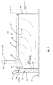
- Figure 1 shows a sectional side view of an enclosure for painting vehicles according to the present invention.
- Figure 2 shows the same enclosure, with a motor vehicle in place.
- a generally rectilinear enclosure 10 is shown erected on a hard-standing surface 11.
- the enclosure comprises an upstanding rear wall 12, a horizontal roof 13 and a front wall comprising a retractable metal curtain 14.
- a inner rear false wall 15 of the enclosure is formed from a filter 16.
- the filter is supported by a metal framework (not shown).
- the filter is a duplex medium, comprising a relatively coarse filter on an enclosure side of the filter, juxtaposed a relatively fine filter medium on the rear wall side of the filter.
- the filter medium comprises an unwoven fibre felt, the coarse and fine progression providing a graduated filter capability for efficiently removing air-entrained paint droplets without unduly restricting airflow through the medium airflow.
- the rear false wall is spaced apart form the rear wall 12 in order to create a vertically extending recirculation duct 17.
- An electrically driven air fan 18 is mounted at a top end region of the rear wall.
- the blades 19 of the fan are accommodated in a top portion of the duct.
- a fresh air bleed vent 20 is provided in a body portion 21 of the fan. The vent communicates with the outside of the enclosure.
- the fan is oriented so that the plane of rotation of the fan is parallel to the back wall.
- a rigid ceiling portion 22 of the enclosure is a sloping planar member.
- the rigid ceiling portion extends upwardly and frontwardly in the enclosure, from a lower portion of the fan up to a planar ceiling filter 24.
- the filter is a planar fibrous felt filter medium supported by a metal framework (not shown). The filter extends across substantially the entire width of the enclosure, and forms about 80% of the ceiling area.
- the space between the roof and ceiling of the enclosure forms a horizontal continuation of the recirculation duct 17'.
- a vertically extending extract duct 25 communicates with a portion of the recirculation duct which is formed adjacent the tapering ceiling portion.
- the duct provides an extract path for venting recirculating air to atmosphere.
- An upper portion 26 of the duct functions a chimney to disperse air-entrained agents into the atmosphere.
- a filter may be placed in the chimney if desired to remove solvents and other undesirable agents.
- One side wall of the enclosure is a solid wall.
- Another side wall of the enclosure may preferably be provided by a flexible curtain, permitting compartmentalisation of a larger hall to form a painting enclosure.
- the flow path of air circulating within the chamber during use is shown by the arrows in figure 1.
- the fan sucks air in the enclosure through the vertical rear wall filter 16.
- the air enters the recirculation duct and travels upwards to the top end of the duct.
- the duct turns a right angle and accommodates the fan blades. Downstream of the fan blades air is funnelled in between the tapering ceiling portion and the roof.
- a proportion of the air in practice about 1,500 to 2,000 cubic feet per minute, is vented to atmosphere through the extract duct.
- the quantity of air recirculating is totals about 12,000 cubic feet per minute.
- the air is ducted over the tope surface of the ceiling filter, and driven through the filter medium into the enclosure.
- the filter medium is relatively fine and provides a uniform input of air into the chamber over substantially the whole ceiling area. Air flow rates in the chamber are adjusted to be about 0.5 m/s to 1.0 m/s. A preferred range is about 0.6 to 0.8 m/s.
- Figure 2 shows the same chamber in use with a motor vehicle 30.
- a substantially non-turbulent laminar flow of air is created over the upper surface of the vehicle.
- Paint is typically effected by an acrylic or isocyanate paint mixture.
- the paint is mixed to match the vehicle colour and sprayed by means of a spray gun applicator.
- the spray is directed onto the blemished or damaged area.
- Extraneous paint which is entrained in the air is carried away by the air, and maintained out of contact of the vehicle body surface by the laminar flow.
- the paint particles are carried as far as the rear wall filter where they are removed by the duplex filter medium.
- the air is then re-circulated, with a proportion of fresh air bled into the system and a proportion bled to atmosphere.
- the atmosphere bleed prevents the build-up of agents such as solvents which are not removed by the applied filter.
- the flow of air ensures that harmful fumes are carried away during painting. It is possible to omit the normal protective clothing and breathing masks required in typical paint shops, particularly where paint volumes applied are very low. This means that a very rapid and convenient painting process may be carried out for the repair of vehicles in a while-you-wait time frame.
- the illustrated embodiment has a single vehicle access at the front of the enclosure. This allows the enclosure to be formed in pre-existing garages and other buildings with minimal modification.
- the enclosure has openable front and rear walls, formed for example from metal shutters or flame retardant curtains.
- An upstanding side wall of the enclosure has formed in a surface thereof the extract duplex filter medium. In this way a recirculation of air in a direction transverse of the vehicle is obtained.
- the vehicle is able to drive into the enclosure through one end and then depart through the other end, providing a drive through painting facility.
Landscapes
- Details Or Accessories Of Spraying Plant Or Apparatus (AREA)
Priority Applications (1)
| Application Number | Priority Date | Filing Date | Title |
|---|---|---|---|
| EP00300690A EP1120168A1 (de) | 2000-01-28 | 2000-01-28 | Fahrzeugslackierkabine |
Applications Claiming Priority (1)
| Application Number | Priority Date | Filing Date | Title |
|---|---|---|---|
| EP00300690A EP1120168A1 (de) | 2000-01-28 | 2000-01-28 | Fahrzeugslackierkabine |
Publications (1)
| Publication Number | Publication Date |
|---|---|
| EP1120168A1 true EP1120168A1 (de) | 2001-08-01 |
Family
ID=8172670
Family Applications (1)
| Application Number | Title | Priority Date | Filing Date |
|---|---|---|---|
| EP00300690A Withdrawn EP1120168A1 (de) | 2000-01-28 | 2000-01-28 | Fahrzeugslackierkabine |
Country Status (1)
| Country | Link |
|---|---|
| EP (1) | EP1120168A1 (de) |
Cited By (2)
| Publication number | Priority date | Publication date | Assignee | Title |
|---|---|---|---|---|
| WO2012085535A1 (en) * | 2010-12-23 | 2012-06-28 | Spraybooth Technology Limited | Spray booths |
| JP6456455B1 (ja) * | 2017-10-25 | 2019-01-23 | 株式会社バンザイ | 自動車用塗装ブース装置 |
Citations (6)
| Publication number | Priority date | Publication date | Assignee | Title |
|---|---|---|---|---|
| US4237780A (en) * | 1979-01-30 | 1980-12-09 | Andrew Truhan | Hydrocarbon fume disposal system particularly for use in paint spray booths |
| US4354451A (en) * | 1980-01-30 | 1982-10-19 | Esb Elektrostatische Spruh- Und Beschichtungsanlagen G.F. Vohringer Gmbh | Device for spray-coating a workpiece with powder particles |
| GB2119500A (en) * | 1981-12-14 | 1983-11-16 | Spraybake Ltd | Ventilating spraybooths |
| US5063835A (en) * | 1990-06-15 | 1991-11-12 | Plaatwerkerij D.W. Slotboom B.V. | Processing booth with variable ventilation |
| EP0568179A1 (de) * | 1992-04-30 | 1993-11-03 | Imperial Chemical Industries Plc | Lackierkabine und Verfahren zur Beschleunigung der Verdampfung des Verdünners aus einer Beschichtung auf einer Plattenoberfläche |
| US5296029A (en) * | 1990-01-25 | 1994-03-22 | Abb Flakt Ab | Spraying booth with arrangement for affecting the motions of paint particles |
-
2000
- 2000-01-28 EP EP00300690A patent/EP1120168A1/de not_active Withdrawn
Patent Citations (6)
| Publication number | Priority date | Publication date | Assignee | Title |
|---|---|---|---|---|
| US4237780A (en) * | 1979-01-30 | 1980-12-09 | Andrew Truhan | Hydrocarbon fume disposal system particularly for use in paint spray booths |
| US4354451A (en) * | 1980-01-30 | 1982-10-19 | Esb Elektrostatische Spruh- Und Beschichtungsanlagen G.F. Vohringer Gmbh | Device for spray-coating a workpiece with powder particles |
| GB2119500A (en) * | 1981-12-14 | 1983-11-16 | Spraybake Ltd | Ventilating spraybooths |
| US5296029A (en) * | 1990-01-25 | 1994-03-22 | Abb Flakt Ab | Spraying booth with arrangement for affecting the motions of paint particles |
| US5063835A (en) * | 1990-06-15 | 1991-11-12 | Plaatwerkerij D.W. Slotboom B.V. | Processing booth with variable ventilation |
| EP0568179A1 (de) * | 1992-04-30 | 1993-11-03 | Imperial Chemical Industries Plc | Lackierkabine und Verfahren zur Beschleunigung der Verdampfung des Verdünners aus einer Beschichtung auf einer Plattenoberfläche |
Cited By (6)
| Publication number | Priority date | Publication date | Assignee | Title |
|---|---|---|---|---|
| WO2012085535A1 (en) * | 2010-12-23 | 2012-06-28 | Spraybooth Technology Limited | Spray booths |
| CN103313799A (zh) * | 2010-12-23 | 2013-09-18 | 斯普瑞布斯科技有限公司 | 喷漆柜 |
| US9643203B2 (en) | 2010-12-23 | 2017-05-09 | Spray-Booth Technology Limited | Spray booths |
| CN108970885A (zh) * | 2010-12-23 | 2018-12-11 | 斯普瑞布斯科技有限公司 | 喷漆柜 |
| JP6456455B1 (ja) * | 2017-10-25 | 2019-01-23 | 株式会社バンザイ | 自動車用塗装ブース装置 |
| JP2019076837A (ja) * | 2017-10-25 | 2019-05-23 | 株式会社バンザイ | 自動車用塗装ブース装置 |
Similar Documents
| Publication | Publication Date | Title |
|---|---|---|
| US5397394A (en) | Powder coating booth | |
| US8479452B2 (en) | Transportable inflatable workstation | |
| EP2390607B9 (de) | Verfahren zur zuführung von luft in eine spritzkabine (ausführungsformen) und lüftungseinheit zur durchführung des verfahrens (ausführungsformen) | |
| US5556324A (en) | Blasting cabinet | |
| EP0631849B1 (de) | Verfahren und Vorrichtung zum Reinigen von Oberflächen | |
| KR101049329B1 (ko) | 도장 가이드장치 | |
| JP2008531243A (ja) | 局所的な回収システム | |
| KR20120111856A (ko) | 벽면 도장 로봇의 비산 방지 장치 | |
| EP1120168A1 (de) | Fahrzeugslackierkabine | |
| US5277652A (en) | Spray booth | |
| US20060243202A1 (en) | Aircraft spray booth | |
| JPH0757332B2 (ja) | 飛沫防止塗装の移動作業床装置及びその工法 | |
| US11077459B2 (en) | Directional air apparatuses, system, and methods of using the same | |
| US8943999B2 (en) | Vehicle collision repair zone | |
| US5221230A (en) | Paint spraying booth with split-flow ventilation | |
| KR101064919B1 (ko) | 일방향 공기 흐름을 제공하는 도장부스용 도어 | |
| PL168021B1 (pl) | Uklad do zabezpieczania urzadzen przed zanieczyszczeniami, zwlaszcza do automatówmalarskich PL PL | |
| JP2003126743A (ja) | 水性塗料用塗装装置 | |
| US20160207166A1 (en) | Spot Blast Cleaning and Containment System | |
| JP3098674U (ja) | 塗装作業に於ける小型排気装置 | |
| GB2087068A (en) | Spray booth | |
| JPH094214A (ja) | 吊り足場装置 | |
| JPS58139759A (ja) | 塗装ブ−ス | |
| WO2019101738A1 (de) | Verfahren zum aufbringen eines pflegemittels auf ein fahrzeug und fahrzeugbehandlungsanlage | |
| GB2428086A (en) | Workstation for refinishing automobile wheels |
Legal Events
| Date | Code | Title | Description |
|---|---|---|---|
| PUAI | Public reference made under article 153(3) epc to a published international application that has entered the european phase |
Free format text: ORIGINAL CODE: 0009012 |
|
| AK | Designated contracting states |
Kind code of ref document: A1 Designated state(s): AT BE CH CY DE DK ES FI FR GB GR IE IT LI LU MC NL PT SE |
|
| AX | Request for extension of the european patent |
Free format text: AL;LT;LV;MK;RO;SI |
|
| 17P | Request for examination filed |
Effective date: 20020201 |
|
| AKX | Designation fees paid | ||
| REG | Reference to a national code |
Ref country code: DE Ref legal event code: 8566 |
|
| STAA | Information on the status of an ep patent application or granted ep patent |
Free format text: STATUS: THE APPLICATION IS DEEMED TO BE WITHDRAWN |
|
| 18D | Application deemed to be withdrawn |
Effective date: 20020202 |